Meditech microVENT World User manual


Instructions: Meditech microVENT
Page 2 of 28
Part number 011-0045-00
DOC300M 17/03/2021 Issue L
This manual refers to the microVENT handset (Serial No:)
BNOS Meditech Ltd. is an ISO 13485:2016 registered company
The microVENT is registered with the U.S. FDA No. K930533
The microVENT is registered with the Canadian Ministry of Health
The microVENT is covered by the following Patents:
(UK) 2270629
(USA) 5537999
(USA) 5351361
Canada Patent No.2107358
European Patent 0578679
EC – DECLARATION OF CONFORMITY CE 2797
These products have been either manufactured or supplied under ISO 13485:2016. B.N.O.S.
Meditech Microvents are supplied in conformity under a quality system to meet Annex II of the Medical
Devices Directive 93/42/EEC as amended 2007/47/EC, Microvents are classified as Class IIa Medical
Devices.
The above quality system has been inspected by the Notified Body Ref: CE 2797 being BSI, Say
Building, John M. Keynesplein 9, 1066 EP Amsterdam, The Netherlands. EC Certificate No. 662942
refers.
Other Standards
microVENTalso comply with the following standards:
ISO 13485:2016
BS 6850:2002 Gas powered ventilatory resuscitators
BS EN ISO 5356-1:2015
ISO 5359:2014 + A1:2017
BS 5682:2015 (where BS standard connector specified by customer).
ISO 15223-1:2016
EN 62366-1:2015
BS EN ISO 15001:2011
BS EN ISO 14971:2019
ISO10524-1:2018
It is also certified that the equipment listed above fully complies with all the required mandatory
standards and the performance, specifications, standards and sources agreed and contracted for this
order.
microVENT is a registered trademark of B.N.O.S Meditech Ltd.
This manual is intended to provide operating instructions on the use of the microVENT® and should be
studied carefully by all persons required to operate the equipment
WARNING
Federal law restricts this device to sale by or on the order of a physician.

Instructions: Meditech microVENT
Page 3 of 28
Part number 011-0045-00
DOC300M 17/03/2021 Issue L
CONTENTS
1 CHAPTER ONE: SYMBOLS ............................................................................................................4
2 CHAPTER TWO……………………………………………………………………………………………….4
2.1 THE MICROVENT ..........................................................................................................5
2.2 INTERNATIONAL CUSTOMERS (OUTSIDE UK) ..............................................................5
2.3 SAFETY PRECAUTIONS ...............................................................................................5
2.4 SPECIFICATIONS..........................................................................................................6
2.5 HOW TO READ AND UNDERSTAND THE MICROVENT SERIAL NO.......................................... 11
3 CHAPTER THREE: GAS SUPPLY.................................................................................................12
3.1 GAS SUPPLY CONNECTIONS .................................................................................... 12
3.2 CONNECTING TO ACYLINDER ..................................................................................12
4 CHAPTER FOUR: OPERATING PROCEDURE............................................................................. 13
4.1 MANUAL VENTILATION AND CARDIAC MASSAGE (CPR) ......................................... 13
4.2 AUTOMATIC VENTILATION (DOES NOT APPLY TO MICROVENT RESPONDER)………………………..15
4.3 AIRMIX (AIR ENTRAINMENT OPTION) ………………………………………………………………………16
4.4 USE IN TOXIC ATMOSPHERES ..................................................................................18
4.5 USE IN CLEAN ATMOSPHERES................................................................................. 20
4.6 ACTION TO BE TAKEN IF PATIENT VOMITS DURING RESUSCITATION .................. 21
4.7 ADDITIONAL CONSIDERATIONS................................................................................ 22
5 CHAPTER FIVE: SERVICING ........................................................................................................22
5.1 ROUTINE MAINTENANCE ...........................................................................................22
5.2 CHECKLIST –IN FULL AT LEAST EVERY MONTH AND AFTER EACH USE. ............................ 23
5.3 CLEANING THE MICROVENT ANDACCESSORIES ......ERROR!BOOKMARK NOT DEFINED.
5.4 PRODUCT LIFE SPAN .................................................................................................25
FIGURE 1: THE MICROVENT (ADULT / CHILD MODEL ILLUSTRATED)....................................... 15
FIGURE 2: OPENING THE AIRWAY ................................................................................................16
FIGURE 3: OPERATING THE MICROVENT - USING THE MANUAL TRIGGER.............................. 17
FIGURE 4: MICROVENT WITH AIRMIX............................................................................................17
FIGURE 5: COMPONENT ASSEMBLY ............................................................................................17
APPENDIX 1: MATERIALS SPECIFICATION.................................................................................... 26
APPENDIX 2: SPARE PARTS ..........................................................................................................27

Instructions: Meditech microVENT
Page 4 of 28
Part number 011-0045-00
DOC300M 17/03/2021 Issue L
CHAPTER ONE: SYMBOLS
Indicates a potentially hazardous situation which could
result in injury to the user or others, if not avoided.
Read these instructions before using the equipment
Do not use any form of grease or oil
No Smoking
Do not use this device near any source of ignition
Product part number
Serial Number
Manufactured by
Next Maintenance or Service Due date
Vti
Inspiratory Tidal Volume
Medical Device
Instructions: Meditech microVENT
Page 5 of 28
Part number 011-0045-00
DOC300M 17/03/2021 Issue L
CHAPTER TWO: THE MICROVENT
2.1 INTRODUCTION
2.1.1 The microVENT World, European, CPR and Classic models are oxygen powered, automatic
time cycled microVENT with MANUAL TRIGGERING for use in conjunction with respiratory
arrest, respiratory difficulties and external cardiac massage designed to deliver oxygen
ventilation to patients by way of a face mask or airway device attached to the microVENT.
The device is designed for use by trained individuals/clinicians who are familiar with the
device.
2.1.2 The microVENT Responder is an oxygen powered, manually operated microVENT. The
“Responder” has no automatic function.
2.1.3 The microVENT UtilityVenT is an oxygen powered automatic time cycled microVENT. Unlike
other microVENT it has no manual trigger.
2.1.4 The oxygen used by the Microvent has two functions. The latent energy of the compressed
oxygen gas is used to power the microVENT. This means that the microVENT requires no
other power source. It requires no batteries or mains electricity. The oxygen itself is then
used at low pressures to ventilate the patient’s lungs and thereby support life.
2.1.5 The microVENT is available as a handset unit without accessories or case. This can be
attached to suitable oxygen specific outlet, such as in a hospital or ambulance, or a medical
oxygen cylinder regulator. The purchaser is responsible for the provision of accessories
needed to operate the handset unit such as a suitable oxygen source and resuscitation
facemasks.
2.1.6 microVENT is also available from the manufacturer as a resuscitation kit. The microVENT
Resuscitator Kit includes the accessories needed for normal use. (Oxygen cylinder not
included but available as a separate item.) A complete kit can be purchased by “building” the
contents as shown in the sales brochures. Contact the sales department for more details.
2.2 INTERNATIONAL CUSTOMERS (outside UK)
2.2.1 All microVENT can be supplied with alternative supply fittings and colour coding to meet the
requirements of the country of use. Meditech regulators can also be supplied in international
configurations to fit alternative national cylinder fittings and with output fittings meeting national
requirements.
2.3 SAFETY PRECAUTIONS
2.3.1 This manual is intended to provide operating instructions on the use of the microVENT® r and
should be studied carefully by all persons required to operate the equipment
WARNING:Federal law restricts this device to sale by or on the order of a physician.
WARNING:
Oxygen supports combustion. While the unit is in use, do not smoke or use a naked
flame either during resuscitation, when providing oxygen therapy or when changing
the cylinder.
Never use oil, grease or solvents on any part of the cylinder, regulator or resuscitator.

Instructions: Meditech microVENT
Page 6 of 28
Part number 011-0045-00
DOC300M 17/03/2021 Issue L
WARNING: DEADSPACE - Users/Clinicians are able to determined their own
style of face mask or airway device. However, the user will need to ensure that
the dead space of any combination used meets the requirements of dead space
statement below:
The dead space of the Microvent is no more than 6ml applicable to all models.
The total dead space will vary depending on face masks or airways used with the device.
Note: The dead space of any combination of facemask or airway device attached to the
microVENT must not exceed 100ml or more when the device is used to deliver more than
300ml (Tidal Volume). When the device is used to deliver 300ml (Tidal Volume) or less the
dead space of combination of facemask or airway device the dead space should not
exceed 30% of minimum delivered volume.
WARNING: The Microvent must only be used by persons who have received
adequate training because incorrect operation of the resuscitator can be hazardous.
The Microvent should not be used on unattended patients, a competent user should be
present when the device is used. Users should be trained in alternative methods of
ventilation e.g. Mouth to mouth, BVM
CAUTION: "Hands on" training sessions should be undertaken on a regular basis to
familiarise operatives with the equipment and its functions.
2.3.2 At intervals in this manual WARNING and / or CAUTION boxes are used. Please ensure that
these are read and understood.
2.3.3 This microvent is intended for first responders / paramedics / clinicians / trained users to a
breathing emergency only and patients must be transferred to a transport / emergency
ventilator conforming to ISO10651-3 as soon as such equipment becomes available. For
information this resuscitator does conform to technical requirements of ISO10651-3.

Instructions: Meditech microVENT
Page 7 of 28
Part number 011-0045-00
DOC300M 17/03/2021 Issue L
SPECIFICATIONS
microVENT
Classic, Airmix,
Adult / Child
microVENT
Classic,
Adult/Child
microVENT
World, Airmix,
Adult/Child
microVENT
World,
Adult/Child
microVENT
CPR
Part Number-
Advanced
model (UK
specification)
670-0060-00 670-0010-00 670-0531-00 670-0506-00 N/A
Part Number-
Standard
model (UK
specification)
670-0061-00 670-0009-00 670-0539-00 670-0511-00 670-
0483-00
Patient
population
range
Adult Adult Adult Adult Adult
Child above 20
kg
Child above 20
kg
Child above 10
kg
Child above 10
kg
Child
above10
kg
Automatic
operation
Time cycled.
Gas powered.
(Patient assist
synchronisation
fitted on
Advanced
models)
Time cycled.
Gas powered.
(Patient assist
synchronisation
fitted on
Advanced
models)
Time cycled.
Gas powered.
(Patient assist
synchronisation
fitted on
Advanced
models)
Time cycled.
Gas powered.
(Patient assist
synchronisation
fitted on
Advanced
models)
Time
cycled.
Gas
powered
Automatic
flow rate
(L/min)
43.2 to 21.6 43.2 to 21.6 36 to 11.25 36 to 11.25 36 to 9
Automatic
tidal volume
(L)
1.2 to 0.3 1.2 to 0.3 1.0 to 0.15 1.0 to 0.15 0.6 to
0.15
Automatic
oxygen
concentration
V/V
100% or
50%(nominal) 100% 100% or
50%(nominal) 100% 100%
Automatic I:E
ratio 1:2 1:2 1:2 1:2 1:5
Automatic
frequency
(per minute)
12 to 24 12 to 24 10 to 25 10 to 25 10
Manual flow
rate (L/min) 40 40 40 40 40

Instructions: Meditech microVENT
Page 8 of 28
Part number 011-0045-00
DOC300M 17/03/2021 Issue L
microVENT
European,
Adult/Child
microVENT
European,
Adult only
microVENT
UtilityVenT,
European,
Adult only
microVENT
Responder
Part Number-
Advanced
model (UK
specification)
670-0215-00 670-0261-00 670-0339-00
670-0312-00
Part Number-
Standard
model (UK
specification)
670-0213-00 670-0259-00 670-0583-00
Patient
population
range
Adult
Adult Adult
Adult
Child over 14
kg
Child over
10 kg
Automatic
operation
Time cycled.
Gas powered.
(Patient assist
synchronisation
fitted on
Advanced
models)
Time cycled.
Gas powered.
(Patient assist
synchronisation
fitted on
Advanced
models)
Time cycled.
Gas powered.
(Patient assist
synchronisation
fitted on
Advanced
models)
Gas
powered.
Manual
operation.
No
automatic
operation.
Automatic
flow rate
(L/min)
21.5 to 15.5 21.5 21.5
No
automatic
operation
Automatic
tidal volume
(L)
0.6 to 0.2 0.6 0.6
No
automatic
operation
Automatic
oxygen
concentration
V/V
100% 100% 100%
No
automatic
operation
Automatic I:E
ratio 1:2 1:2 1:2
No
automatic
operation
Automatic
frequency
(per minute)
12 to 25 12 12
No
automatic
operation
Manual flow
rate (L/min) 40 40 No manual
operation
40 or 20
(user
selectable)

Instructions: Meditech microVENT
Page 9 of 28
Part number 011-0045-00
DOC300M 17/03/2021 Issue L
microVENT
Classic,
Airmix, Adult
/ Child
microVENT
Classic,
Adult/Child
microVENT
World,
Airmix,
Adult/Child
microVENT
World,
Adult/Child
microVENT
CPR
Pressure relief valve
with audible warning
limits maximum
attainable delivery
pressure (kPa)
4.5 (6.0 on
request)
4.5 (6.0 on
request)
4.5 (6.0 on
request)
4.5 (6.0 on
request)
4.5 (6.0 on
request)
Expiratory resistance
(kPa) <0.5 <0.5 <0.5 <0.5 <0.5
Patient assist trigger
pressure on
advanced models
(kPa)
<-0.5 <-0.5 <-0.5 <-0.5
Not
applicable
on
"Standard"
model
Inspiratory
resistance without
anti-air-entrainment
diaphragm (kPa)
<0.5 <0.5 <0.5 <0.5 <0.5
Resuscitator weight-
excluding supply
hose (g)
262
(advanced)
214
(advanced)
262
(advanced)
214
(advanced)
210
250
(standard)
202
(standard)
250
(standard)
202
(standard)
Maximum
resuscitator
dimensions-
excluding supply
hose (mm)
120 x 55 x
100
120 x 55 x
100
120 x 55 x
100
120 x 55 x
100
120 x 55 x
100
Approximate
duration when
operating on
automatic from 340L
"D" size cylinder at
10 L minute volume
(minute)
32, Airmix
60 32 32 32 N/A
Approximate
duration when
operating on
automatic from 400L
size cylinder at
maximum minute
volume (minute)
27, Airmix
54 27 38, Airmix 76 38 60
Approximate
duration when
operating on manual
from 400L size
cylinder with two
600mL breaths given
every 24 seconds
(minute)
125 125 125 125 125

Instructions: Meditech microVENT
Page 10 of 28
Part number 011-0045-00
DOC300M 17/03/2021 Issue L
microVENT
European,
Adult/Child
microVENT
European,
Adult only
microVENT
UtilityVenT,
European,
Adult only
microVENT
Responder
Pressure relief valve
with audible warning
limits maximum
attainable delivery
pressure (kPa)
4.5 (6.0 on
request)
4.5 (6.0 on
request)
4.5 (6.0 on
request)
4.5 (6.0 on
request)
Expiratory resistance
(kPa) <0.5 <0.5 <0.5 <0.5
Patient assist trigger
pressure on
advanced models
(kPa)
<-0.5 <-0.5 <-0.5 Not
applicable
Inspiratory
resistance without
anti-air-entrainment
diaphragm (kPa)
<0.5 <0.5 <0.5 <0.5
Resuscitator weight-
excluding supply
hose (g)
214
(advanced)
214
(advanced)
214
(advanced)
200
202
(standard)
202
(standard)
202
(standard)
Maximum
resuscitator
dimensions-
excluding supply
hose (mm)
120 x 55 x
100
120 x 55 x
100
120 x 55 x
100
120 x 55 x
100
Approximate
duration when
operating on
automatic from 340L
"D" size cylinder at
10 L minute volume
(minute)
N/A N/A N/A N/A
Approximate
duration when
operating on
automatic from 400L
size cylinder at
maximum minute
volume (minute)
50 50 50 N/A
Approximate
duration when
operating on manual
from 400L size
cylinder with two
600mL breaths given
every 24 seconds
(minute)
125 125 N/A 125

Instructions: Meditech microVENT
Page 11 of 28
Part number 011-0045-00
DOC300M 17/03/2021 Issue L
2.4.1 Operating environmental limits: -18 to +50 degrees Celsius, at 0 to 95 % non-condensing
humidity.
2.4.2 Storage environmental limits: -40 to +60 degrees Celsius, at 0 to 95 % non-condensing
humidity.
2.4.3 The microVENT is an automatic time cycled resuscitator. It is also a manually controlled gas
powered device and when manually controlled the tidal volume and frequency are controlled
directly by the operator. (Note: The microVENT UtilityVenT is an automatic only device, the
microVENT Responder is a gas powered manual operated device – see specification pages
and sales brochures for more details.)
2.4.4 The microVENT has a maximum attainable pressure of 45 cm water (4.5 kPa) unless otherwise
specified by customer request. This is controlled by the pressure relief cap (The pressure relief
setting is marked on the pressure relief cap).
2.4.5 Drive gas consumption to operate microVENT – Negligible.
2.4.6 Inspiratory resistance without Anti-Air-Entrainment diaphragm <0.5 cm H2O (0.05 kPa).
WARNING: Fitting the Anti-Air-Entrainment diaphragm prevents spontaneous inhalation
of atmospheric air through the Microvent. In the event of failure of the oxygen supply this
could result in the patient being unable to breathe through the Microvent.
2.4.7 End-expiratory pressure in normal use is atmospheric pressure.
2.4.8 The microVENTis pressure limited by the pressure relief cap which incorporates a calibrated
spring loaded seal underneath the pressure relief cap. When patient airway pressure exceeds
4.5kPa the relief cap diaphragm/seal will lift and will relieve flow and subsequently ensure that
patient airway pressure does not exceed the stated value.
2.4.9 Tolerances according to ISO10651-5:2006.The accuracy of specified ventilation parameters
and all other performance related parameters are within the tolerance of +/-10% of the stated
nominal value.
2.4.10 The delivered volume or minute volume and oxygen concentrations are not affected by
pressure at the patient connection unless the patient airway pressure exceeds 45cm H2O
(4.5kPa) at which point the pressure relief valve within the pressure relief cap will operate.
2.4 HOW TO READ AND UNDERSTAND THE MICROVENT SERIAL NO.
2.5.1 Serial number can be found on the underside of the microVENT, next to the manual
trigger.
Example M V R 0 1 1 2 5 5 5 5 5
The first letters refer to the type of microVENT.The next four numbers refer to the month and year of
manufacture, in the example January (01) 2012 (12). The last five numbers refer to the production
number of the unit. When communicating about your microVENT please quote the serial number in full.
Instructions: Meditech microVENT
Page 12 of 28
Part number 011-0045-00
DOC300M 17/03/2021 Issue L
3 CHAPTER THREE: GAS SUPPLY
3.1 GAS SUPPLY CONNECTIONS
3.2 CONNECTING TO A CYLINDER
3.2.1 Follow the instructions provided by the cylinder supplier and regulator manufacturer.
WARNING
Oxygen supports combustion. While the unit is in use, do not smoke or use a naked
flame either during resuscitation, when providing oxygen therapy or when changing the
cylinder.
Never use oil, grease or solvents on any part of the cylinder, regulator or microVENT.
CAUTION
When connected to a portable supply such as a small cylinder and regulator always turn
off the oxygen at the cylinder valve when the microVENT is not in use. This is to prevent
the cylinder becoming empty due to leakage.
CAUTION
The microVENT is dependent upon the oxygen supply to enable it to function. Always
ensure adequate supplies of oxygen are available. Monitor the use of the cylinder by
observing the contents gauge.
3.1.1 The microVENT is designed to operate on medical oxygen from either a cylinder or pipeline. In
the UK the connection fittings are of the shrouded BS 5682: 2015 quick connect type unless
otherwise specified by the customer and allowed under the applicable relevant international
standard. Other types of connections are supplied as the standard fittings in non-UK countries
.
3.1.2 The microVENT can also be supplied ready to operate on medical air, in this event a medi
cal air
connection will be used.
3.1.3 The supply pressure should be within the range of 2.8 – 6 bar and should not exceed 10 bar.
Medical gas supplies should where applicable meet the requirements of ISO10651-5 (howe
ver
other standards now define medical gas supplies including pressure regulators). Pressure
regulators meeting the requirements of ISO10524-1:2019 are considered to have superseded
the pressure requirements of ISO10561-5 and are ideal for use with the Microvent.

Instructions: Meditech microVENT
Page 13 of 28
Part number 011-0045-00
DOC300M 17/03/2021 Issue L
4 CHAPTER FOUR: OPERATING PROCEDURE
4.1 MANUAL VENTILATION AND CARDIAC MASSAGE (CPR)
4.1.1 The application of oxygen is recommended as soon as it is available in both basic life support
and advanced life support.1,2
4.1.2 The Resuscitation Guidelines 2000 and 2005 highlighted the advantages of resuscitating with
lower volumes and flow rates. These help to limit airway pressures reducing the chances of
gastric insufflation, vomiting and subsequent aspiration and pneumonia.1,2,3
4.1.3 With 100% oxygen resuscitation we help ensure oxygenation at these smaller tidal volumes.
4.1.4 The microVENT is fitted with a Manual Trigger to help the user to resuscitate the patient
following the appropriate basic life support resuscitation guidelines.
4.1.5 By using the Manual Trigger the operation of the device can be easily timed with the chest
compressions following the latest recommendations to ventilate during CPR at a ratio of two
ventilations to 30 compressions 4. Squeezing the trigger initiates flow of 100% oxygen from the
device. Releasing the trigger allows the patient to exhale. The microVENT is designed to enable
the user to hold the resuscitation mask and control the airway with a two-handed grip,
operating the trigger with one finger (Fig:4). The use of the two-handed grip enables the user
to control the airway and give a good seal to the face mask. This grip is considered easier to
perform than the one-handed grip needed when operating a bag-valve-mask.
4.1.6 All microVENTsfeature a pressure relief valve that prevents dangerous airway pressures being
achieved. An audible warning sounds when the relief valve is operating. Users should use the
test method described 5.3.18 (within warning section). The principle of the alarm detection is
that the pressure relief valve will relieve pressure within the device and therefore the patient
mask / airway device / patient airway and also simultaneously sound the alarm when the
delivered pressure by the means described above exceeds 45cm H2O / 4.5kPA. the pressure
relief valve and alarm function will continue to operate and the alarm will be audible until the
pressure drops below 45cm H2O / 4.5kPa.
4.1.7 Advanced models of the Microvent are fitted with a Patient Assist Valve. The Valve is
connected via a port to the patient connection (patient valve) and will trigger an inspiratory
phase of one breath (at the same BPM and Vti at which the device is currently set) if the
patient assist valve detects a negative pressure at the patient connection of -2.5cm H2O/ (-
0.25kPa) during the exhalation phase of automatic mode of cycling. The inspiration phase will
follow i.e. as per normal automatic cycling. The patient assist valve only operates during
automatic resuscitation and is disabled in the manual mode. If the patient assist valve
continues to detect the required negative pressure to trigger its operation after one cycle has
been delivered it will continue to deliver breaths. This ventilation mode is sometimes known
as SIPPV (Synchronised Intermittent Positive Pressure Ventilation).
WARNING
At all times during resuscitation the rise and fall of the patient's chest should be
monitored to ensure adequate ventilation.
CAUTION
Users are recommended to consult the ILCOR / AHA / ERC / UK or their national
resuscitation guidelines regarding the latest recommendations for CPR.
References:

Instructions: Meditech microVENT
Page 14 of 28
Part number 011-0045-00
DOC300M 17/03/2021 Issue L
1 American Heart Association in collaboration with the International Liaison Committee on Resuscitation (ILCOR). Guidelines 2000 for
cardiopulmonary resuscitation and emergency cardiovascular care. An international consensus on science. Circulation
2000;102(Suppl.I):I-1 –I-384.
2 American Heart Association in collaboration with the International Liaison Committee on Resuscitation (ILCOR). Guidelines 2000 for
cardiopulmonary resuscitation and emergency cardiovascular care — An international consensus on science. Resuscitation 2000;46:1–
447.
3 European Resuscitation Council Guidelines 2000 for Adult Basic Life Support
A statement from the Basic Life Support and Automated External Defibrillation Working Group 1 and approved by the Executive
Committee of the European Resuscitation Council. Resuscitation 48 (2001) 199–205
4 Circulation 2005;112;12-18; originally published online Nov 28, 2005;

Instructions: Meditech microVENT
Page 15 of 28
Part number 011-0045-00
DOC300M 17/03/2021 Issue L
Figure 1: The microVENT World (Adult / Child
model illustrated)
Key to components in figure 1:
q = microVENT body
r = Manual / automatic selector
s = Pressure limiting (and audible warning) valve
t = Patient valve assembly
v = Manual trigger
w = Oxygen supply hose
y = Tidal volume and frequency selector (on
Professional - Adult/Child - models not used on
Industrial - Adult Only - models)
Figure 2: The Microvent Pneumatic Circuit
131-0001-00 = Microvent time/flow sub assembly
131-0003-00 = Control valve sub assembly
131-0006-00 = Patient assist assembly
131-0002-00 = Regulator sub Assembly
131-0004-00 = Microvent manual trigger sub assembly
131-0010-00 = Relief sub assembly

Instructions: Meditech microVENT
Page 16 of 28
Part number 011-0045-00
DOC300M 17/03/2021 Issue L
4.1.7 Having established that the patient is not breathing, position the patient as for mouth-to-mouth
resuscitation. The airway can be opened by head tilt, chin lift or jaw thrust. The head tilt
method is illustrated in figure 3.
Figure 3: Opening the airway
4.1.8 Clear the patient's mouth of any foreign materials and check to see if the patient has
commenced spontaneous breathing.
4.1.9 Attach the microVENT to an active regulated gas supply:
•Connect the oxygen input fitting on the microVENT supply hose to the oxygen regulator
attached to the cylinder in accordance with the regulator manufacturers instructions,
turn on the Oxygen Cylinder valve slowly.
•Or connect the oxygen input fitting on the microVENT supply hose to an oxygen wall
outlet in the hospital or ambulance.
4.1.10 On the microVENT select the manual setting (Fig:1,r). Use the appropriate size of Face Mask
and attach to the Patient Valve (t).
4.1.11 If no respiratory effort is observed position yourself above the patient's head and apply the
Face Mask over the patient's nose and mouth and use both hands to obtain a good seal and
support the jaw (Fig:4).
4.1.12 Squeeze the Manual Trigger (Fig:1,v) towards the Face Mask and observe the rise of the
patient's chest. The operation of the Manual Trigger does not require a violent pull. A gentle
squeeze of the trigger will supply oxygen and inflate the lungs.
4.1.13 Excessive pressure on the Manual Trigger will not result in more oxygen being supplied to the
patient, and may damage the device.
4.1.14 Once sufficient patient chest rise has been observed, release the manual trigger so the
resuscitator is no longer inflating the patient’s lungs. This allows the patient to passively
exhale back through the mask and out through the patient valve. It is normal to allow 2 to 3
seconds exhalation (expiratory) time so the patient has completely exhaled. (It is not
necessary to remove the facemask or Microvent from the patient’s face for the patient to
exhale.)
4.1.15 If the patient's chest does not rise or gas escapes around the mask or the Pressure Relief
Valve (Fig:1,s) operates, with an audible tone, reposition the patient's head and adjust your
hand position to obtain an effective seal and an open airway.
4.1.16 Over inflation will be indicated by excessive chest rise and eventually by the operation of an
audible tone of the Pressure Relief Valve. Under inflation will be indicated by too shallow a rise
in the patient's chest.
Instructions: Meditech microVENT
Page 17 of 28
Part number 011-0045-00
DOC300M 17/03/2021 Issue L
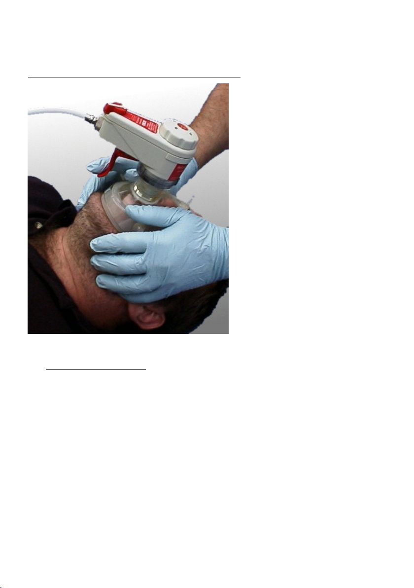
Figure 4: Operating the microVENT using the manual trigger.
The microVENT and face mask can be held in position by both hands while maintaining the patient’s
airway and operating the manual trigger.
4.2 AUTOMATIC VENTILATION
4.2.1 If the patient is suffering from respiratory arrest or respirator insufficiency
If in the event of cardiac arrest, resuscitation restarts the patient’s heart
If the patient is intubated (or the airway is protected by Combitube or LMA)
If circumstances dictate that manual ventilation with the microVENT is not possible or
If the patient is to be transported
Then automatic ventilation may be commenced.
4.2.2 If the patient makes an inspiratory effort during automatic ventilation, Advanced microVENTs
have a respiratory assist sensor which, when the Anti-Air–Inhalation Diaphragm is fitted to the
patient valve, enables the patient to trigger the microVENT inflations in time with their
inspiratory effort. The Advanced microVENT applies the prescribed tidal volume when
triggered, a mode of ventilation sometimes known as SIPPV (Synchronised Intermittent
Positive Pressure Ventilation). If the patient stops breathing spontaneously the microVENT
recommences automatic ventilation after the set expiratory time. The respiratory assist sensor
is a factory fitted option, known as “Advanced”. Models without the respiratory assist sensor
are known as “Standard”.

Instructions: Meditech microVENT
Page 18 of 28
Part number 011-0045-00
DOC300M 17/03/2021 Issue L
4.2.3 On Adult and Child microVENT the tidal volume and frequency of ventilation are controlled by
the slider control on the front of the microVENT. (See figure 1 (y)). The volume is selected by
the user so as to ensure visible and adequate chest rise of the patient. The patient should be
carefully observed so as to ensure correct ventilation.
4.2.4 On Adult only microVENT the tidal volume and frequency are preset and there is no slider
control.
4.2.5 Select the automatic setting (Fig 1,r). Use the appropriate size of Face Mask and attach to the
Patient Valve (t). (or connect to ET tube via an adapter)
4.2.6 If no respiratory effort is observed position yourself above the patient's head and apply the
Face Mask over the patient's nose and mouth and use both hands to obtain a good seal and
support the jaw (Fig:4).
4.2.7 Increase the tidal volume setting of the microVENT (Fig:1,y) until sufficient chest rise is
observed with each breath. The microVENT has a I:E ratio of 1:2, this means twice as long is
allowed for expiration as inspiration (The microVENT CPR has an I:E ratio of 1:5). The patient
valve allows the patient to exhale to atmosphere. (It is not necessary to remove the facemask
or microVENT from the patient’s face for the patient to exhale.)
4.2.8 If the patient's chest does not rise or gas escapes around the facemask or the Pressure Relief
Valve (Fig:1,s) operates, with an audible tone, reposition the patient's head and adjust your
hand position on the mask and jaw to obtain an effective seal and an open airway.
4.2.9 Over inflation will be indicated by excessive chest rise and eventually by the operation of an
audible tone of the Pressure Relief Valve. Under inflation will be indicated by too shallow a rise
in the patient's chest.
WARNING
At all times during resuscitation the rise and fall of the patient's chest should be
monitored to ensure adequate ventilation.
4.3 AIRMIX (AIR ENTRAINMENT OPTION)
Introduction:
4.3.1 Airmix air entrainment is a factory-installed option available on the microVENT. Airmix increases
the duration of a portable oxygen supply by mixing the oxygen with ambient air. The usage of
oxygen at adult settings is approximately halved, so a supply lasts over twice as long as it
would if used at 100% oxygen. The concentration of oxygen (FiO2) available to the patient is
reduced to approximately 50%.
4.3.2 Airmix can currently only be used when the microVENT is used in its automatic mode. The
selector switch should always be returned to the 100% position (indicating 100% oxygen)
when the resuscitator is being used in manual mode.
CAUTION:
The Airmix selector switch has two positions, these are selected by sliding the control
from one extreme of its travel to the other. Failure to position the control at the 100%
position or the 50% position may result in lower delivered volume (Vti) of the Microvent.
Using Airmix:
4.3.3 With the microVENT in automatic mode slide the Airmix control (Fig:5,z) to the 50% position
(Airmix on). Ensure the Airmix control is at the full extent of its travel.
4.3.4 The Airmix will now entrain ambient air and blend this with the oxygen delivered to the patient.
The tidal volume and frequency of the resuscitator will be maintained on adult settings. On
child settings an increase in tidal volume may be experienced due to the nature of entrainment
valve.
Instructions: Meditech microVENT
Page 19 of 28
Part number 011-0045-00
DOC300M 17/03/2021 Issue L
WARNING: On child settings an increase in tidal volume may be experienced when
switching to Airmix due to the nature of entrainment valve.
WARNING: Where exact volumes and oxygen concentrations need to be known users
are advised to use additional monitoring equipment.
4.3.5 Through patient observation ensure that the patient is still being correctly ventilated and
oxygenated.
4.3.6 When the Airmix function is no longer needed then return the Airmix control (Fig:5,z) to the
100% position (Airmix off).
WARNING
The microVENT Airmix when set at 50% entrains gases from the atmosphere when
operating and should not be used in contaminated environments including use in
hazardous or explosive atmospheres. On Airmix models set the Airmix control to the
100% position (Airmix off) if used in a contaminated environment.
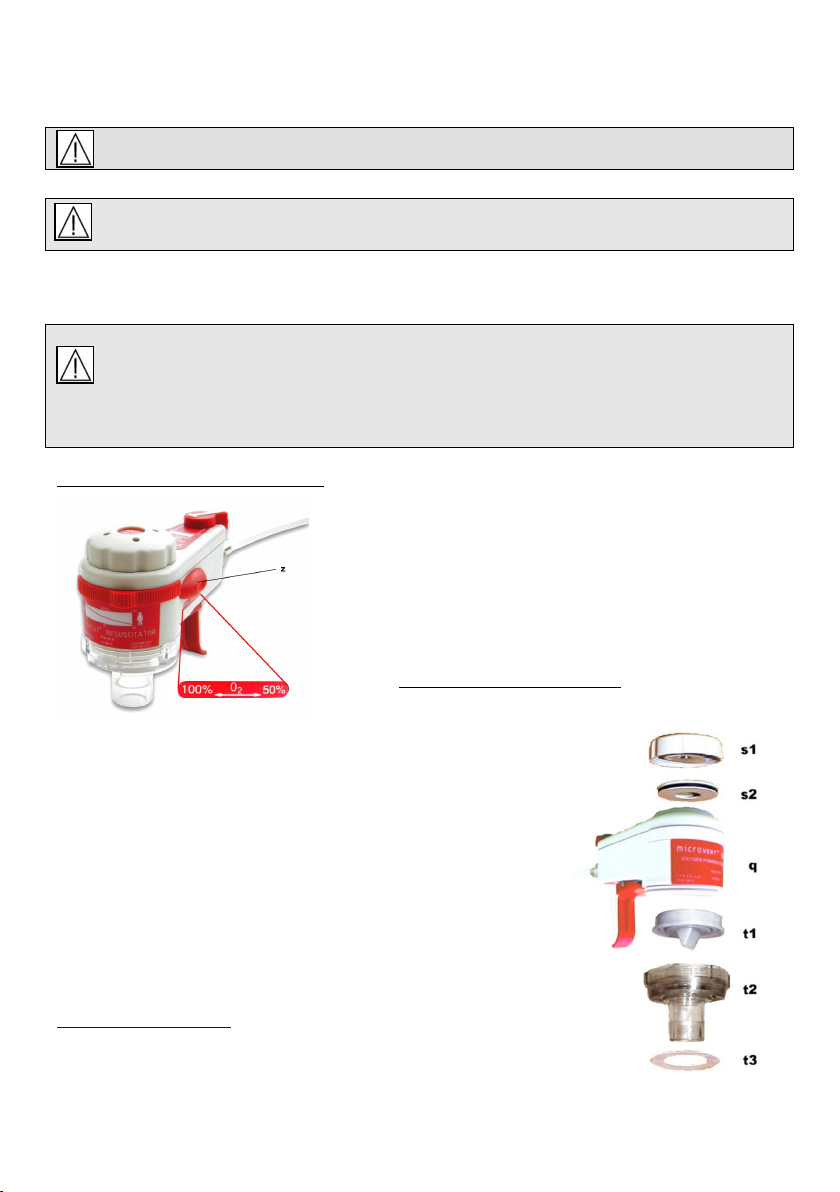
Figure 5: microVENT Wolrd with Airmix
Key to item in Fig 5:
z - Airmix selector switch
Figure 6: Component assembly
The microVENT Component Assembly Inc. Part No.
q microVENT body
s1 Pressure limiting (and audible warning) valve-131-0005-45
s2 Sounding board 131-0183-00
t1 Patient valve diaphragm (duckbill) 673-0011-00
t2 Patient valve body 673-0010-00
t3 Anti-air-inhalation diaphragm 033-1011-00
For spare part numbers also see appendix 2 or contact
sales@meditech.uk.com

Instructions: Meditech microVENT
Page 20 of 28
Part number 011-0045-00
DOC300M 17/03/2021 Issue L
4.4 USE IN TOXIC ATMOSPHERES
4.4.1 During ventilation in atmospheres containing smoke, water or toxic gas, the Anti-Air-Inhalation
Diaphragm (Fig:6,t3) should be fitted to the Patient Valve. This Diaphragm helps ensure that
the patient can receive only pure oxygen during ventilation. Anti-Air-Inhalation is achieved by
fitting a simple removable diaphragm onto the Patient Valve.
WARNING
The microVENT Airmix when set at 50% entrains gases from the atmosphere when
operating and should not be used in contaminated environments. On Airmix models set
the Airmix control to the 100% position (Airmix off).
4.5 USE IN CLEAN ATMOSPHERES
4.5.1 When the Anti-Air-Inhalation-Diaphragm (Fig:6,t3) is fitted and the microVENT is being used
on a patient, if the oxygen supply runs out the patient will not be able to breath ambient air
spontaneously through the Microvent.
WARNING
The patient cannot breathe ambient air when the Anti-Air-Inhalation Diaphragm is fitted,
continued use of the anti-air-inhalation diaphragm on an advanced model Microvent will allow
the patient to inhale 100% oxygen if an inspiratory effort is made by the patient. The anti-air-
inhalation diaphragm is not recommended for use on a standard model microVENT. The
standard model microVENT is not principally designed for use in a toxic environment however
if a standard model microVENT is used in a toxic environment for reasons of emergency and
has the anti-air-inhalation diaphragm fitted it is essential that the diaphragm is removed as
soon as possible when the patient is moved to a safe non-toxic environment. If an anti-air-
inhalation diaphragm is used with a standard model microVENT, which is not recommended by
the manufacturer risks associated with use of the device will increase.
This manual suits for next models
5
Table of contents
Other Meditech Medical Equipment manuals


