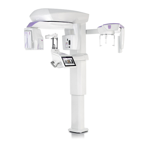
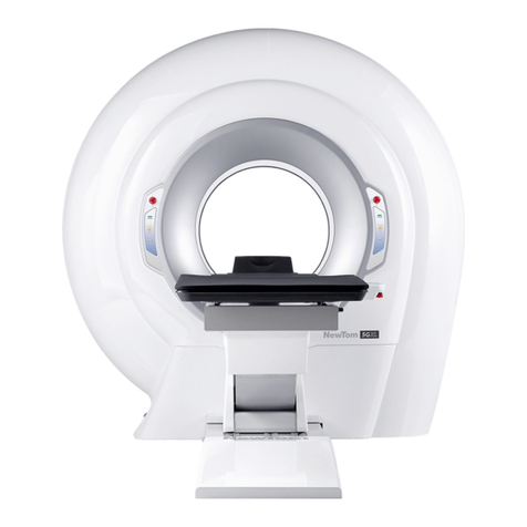
CEFLA NEWTOM 5GXL User manual

97070044
Rev. 2
28.10.2016
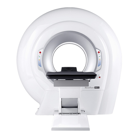
NewTom 5G XL –Installation Manual
EN

NOTES
This document is provided as a consultation manual intended for the device users.
CEFLA s.c. follows a policy based on the constant development and update of the product. For this reason, it
reserves the right to change the content of this manual without prior notice.
This document can not be modified, copied, reproduced, distributed, saved on magnetic or optical supports, or published on
websites and other on-line services, in full or in part, without the prior written authorisation of CEFLA s.c.
The original version of this manual is in English.
NEWTOM™ 5G is a trademark of CEFLA s.c.
All other products and trade names mentioned in this document are registered marks of the relevant manufacturers.
INFORMATIVE NOTE OF THE MANUFACTURER ON THE MEDICAL DEVICES
The medical device referred to in this manual consists of a scanner and a control, display and calculation unit (Main
Workstation). Such device, as delivered and configured by the production and assistance technical personnel, is an
X-ray device compliant with the safety requirements set forth by the Italian Legislative Decree of 19 September 1994,
no. 626 implementing Directives 89/391/EEC, 89/654/EEC, 89/655/EEC, 89/656/EEC, 90/269/EEC, 90/270/EEC,
90/394/EEC and 90/679/EEC concerning the improvement of the health and safety of workers in the workplace, and
with the essential requirements set forth by the Italian Legislative Decree 24 February 1997, no. 46 implementing
Directive 93/42/EEC as amended, on the medical devices.
The medical device referred to in this manual is an X-ray device compliant with Directive 2011/65/EU on the
restriction of the use of certain hazardous substances in electrical and electronic equipment.
Any tampering with, modification, updating or other change both of hardware1and software2of the device as
supplied and installed by the company (and in the conditions specified in the attached documentation) may partially
or totally compromise the device expected operation. This may also alter the safety features with consequent hazard
increase for patients, operators and surrounding environment.
For this reason, should the user need to modify the device, he/she must request a written authorisation by CEFLA
s.c.
Failure to comply with what is specified in this informative note will null and void the device warranty and the civil
and/or penal responsibility for any consequent damage and/or accident and/or worsening of the patient, operator or
other people health (including the surrounding environment) will be borne by the person who tampered with the
device or his/her legal representative.
1
Adding of a new memory expansion, a new hardware on the connection bus, a printer, the replacement
of the graphic display interface represents an important modification.
2
Including the operative system and the applications already installed upon medical device delivery.
Automatic updates of the operative system, changes to network connection parameters, modification
and/or addition and/or removal of interface software with hardware (device driver) and/or services (e.g.
file and printer sharing service) and/or applications represent an important modification.
SUMMARY
1TARGET AND APPLICATION FIELD............................................................................................................................... 1-1
1.1 CONTENTS ............................................................................................................................................................... 1-1
2UNPACKING AND MOVING THE EQUIPMENT............................................................................................................... 2-1
2.1 SCANNER INSPECTION AND UNPACKING INSTRUCTIONS ........................................................................................................... 2-1
2.2 MOVING THE DEVICE ................................................................................................................................................... 2-8
2.3 PATIENT TABLE INSPECTION AND UNPACKING INSTRUCTIONS..................................................................................................... 2-9
3MOUNTING AND CONNECTING THE EQUIPMENT ........................................................................................................ 3-1
3.1 MOUNTING THE EQUIPMENT ......................................................................................................................................... 3-1
3.2 CONNECTING THE EQUIPMENT........................................................................................................................................ 3-6
3.2.1 Connecting the power supply....................................................................................................................... 3-6
3.2.2 Connecting the console wokstation .............................................................................................................. 3-9
3.2.3 Connecting the external emergency button ................................................................................................... 3-9
3.2.4 Connecting the Ready State Switch (optional)................................................................................................ 3-9
3.2.5 Connecting the X Ray Emission State (optional) ........................................................................................... 3-10
3.2.6 Connecting the External Door switch (optional) ........................................................................................... 3-10
3.2.7 Connecting the patient table ..................................................................................................................... 3-10
3.3 TESTING THE EQUIPMENT............................................................................................................................................ 3-11
3.3.1 Electrical Safety Checks ............................................................................................................................. 3-11
3.3.2 Other tests............................................................................................................................................... 3-11
3.4 DEVICE CALIBRATION ................................................................................................................................................. 3-11
3.5 FINISHING TOUCHES .................................................................................................................................................. 3-11

NewTom 5G XL –Installation Manual rev 0.1 Pag. 1-1
1 Target and application field
1.1 Contents
This documenti is an attachment of the “Service Manual” and has been designed as a guide for a correct installation of the
“NewTom 5G XL”device.
Together with the “Service Manual”of the device it has to be read and fully understood prior to operate on the equipment.

NewTom 5G XL –Installation Manual rev 0.1 Pag. 2-1
2 Unpacking and moving the equipment
2.1 Scanner inspection and unpacking instructions
Thoroughly inspect the exterior of the crates for damages that might have occurred during shipment. Report any
damage to delivering carrier and follow their instructions.
Each crate is equipped with a tilt watch indicator that turns from white to red if the package has tilted during shipment.
Check the indicator before opening the crates.
WARNING:
During the process of unpacking, dismounting and re-mounting the
equipment, Electro Static Discharges (ESD) may occur.
Please refer to the “Service Manual” document for a proper protection
against ESD.
1. Carefully open the crate with the help of a hammer and crowbar. Remove the top and all four-side panels.
2. Remove all the packing materials and store all the boxes in a safe place. Carefully inspect all components inside the
crate for signs of any shipping or internal damage.
Do not attempt set-up, installation, or operation of any damaged system.

NewTom 5G XL –Installation Manual rev 0.1 Pag. 2-2
3. From the base of the crate remove the two lifting tubular bars, the two flat junctions bar and the four “T”
shaped lifting screws.
4. Remove the bubble wrap protection from the scanner.
5. Remove the “Front Panel Thermoformed Carter” (97465033)
Remove the M4x20 hex. socket screw on the left side of the Front Panel Thermoformed Carter (see following
image)
Lower the Front Panel Thermoformed Carter (1) in order to unhook it from the top, therefore pull the panel (2)
to unhook it from the right side.

NewTom 5G XL –Installation Manual rev 0.1 Pag. 2-3
6. Remove the anterior “Plastic Ring” (97465075).
Remove the self-tapping screw on the plastic ring (1), gently pull the plastic ring from the top and disconnect
the keyboards and the emergency buttons (2). Once done pull the ring completely out (3).
7. Removing the “Plastic Cylinder” (97465076).
Remove the Plastic Cylinder from the inside of the gantry. Grab the cylinder from above and accompany while
it get out (see photo).
8. Remove the posterior “Plastic Ring” (97465075)
Remove the self-tapping screw on the plastic ring (1) and then gently pull the plastic ring completely out (2).

NewTom 5G XL –Installation Manual rev 0.1 Pag. 2-4
9. Remove the “Anterior Thermoformed Carter” (97465031)
Remove the 8 bolts that hold the carter (1) and then gently pull the carter completely out (2).
10. Remove the “Posterior Thermoformed Carter” (97465032)
Remove the input plate (1), then remove the 8 bolts that hold the carter (2) and then gently pull the carter
completely out (2). Pay attention to slowly pass the power cable through the carter while moving it.
11. Remove the block-chassis plate (1) from the main structure (see picture below).

NewTom 5G XL –Installation Manual rev 0.1 Pag. 2-5
12. Unlock the counterweight of the cable chain by removing the M8x80 hex screw (2) (see picture below).
13. Unscrew 4 nuts from the bottom of the crate base, then remove the 4 M10x210 hex screws from the 4 wood
spacer supports, located below the holes designed for the adjustment of the device feet.
14. Place the two tubular lifting bars below the device base and verify they match with the by main structure tubular.
The lifting bars include references for a correct positioning (verify they are not positioned below the electronic
plate).

NewTom 5G XL –Installation Manual rev 0.1 Pag. 2-6
WARNING:
It is very important that the lifting bars are correctly positioned on both
the right and left side in order to ensure the device to be balanced
during the lifting process.
15. Install the front and rear junction flat bar using 4 M5 screws provided with the equipment. These bars connect
the two lifting bar together, forming a rigid and solid frame.
WARNING:
It is very important to properly mount the two junction bars in order to
stabilize the device during the lifting process.
16. Mount the four ”T” shaped lifting screws on the lifting bars, and position the 4 plastic feet.
17. Slowly lift the device by equally screwing the four ”T” shaped lifting screws, until the wood spacer supports can be
removed.
Be careful to do not tilt too much the equipment during the lifting process.

NewTom 5G XL –Installation Manual rev 0.1 Pag. 2-7
18. Remove the base of the crate, paying attention to do not bang into the 4 lifting screws.
19. Slowly lower the device by equally unscrewing the 4 ”T” shaped lifting screws, until the it rest on the wheels.
Be careful to do not tilt too much the equipment while lowering it.
20. Remove the ”T” shaped lifting screws, the plastic feet, the junction bars and the lifting tubular bars.

NewTom 5G XL –Installation Manual rev 0.1 Pag. 2-8
2.2 Moving the device
Once the machine rests on the wheels (without any cover mounted) it can be carefully moved to the final position.
WARNING:
In case the device needs to travel through a ramp, move it down
sideway. Maximum admitted inclination is 10%.
In case the device needs to be lifted with the aid of a a crane, it is possible to roped it up using belt with 1000 Kg (2204
lb) capacity, secured to the front and rear side of the main structure as shown in the following picture.
Alternately, four M12 threaded holes are provided in order to mount 4 lifting rings (see following picture).

NewTom 5G XL –Installation Manual rev 0.1 Pag. 2-9
Once the device is in the final position the wheels must be replaced with the provided support feet.
Place the each foot below the corresponding M12x140 screws, then equally tighten each screw in order to lift up the
device, until the wheels are free and can be removed (see following picture).
Once all the wheels have been removed lower down the equipment by equally loosing each screw until the two frontal
screws responsible for the table coupling, matches with the table holes.
1 M12x140
hex screw
99934441 – SUPPORT FEET
2.3 Patient table inspection and unpacking instructions
For unpacking, moving and preparing the patient table for the installation please refer to the provided “Patient Table
Installation Manual”.

NewTom 5G XL –Installation Manual rev 0.1 Pag. 3-1
3 Mounting and connecting the equipment
3.1 Mounting the equipment
1. Mount the Posterior Thermoformed Carter (97465032)
First, gently place the carter on the scanner by matching the holes of the carter with the spacers mounted on
the structure (see details on image 1).
Once the carter is in the correct position, fix it with by tightening n°8 6x20 TCEI bolts with M6x24 flat washers
(2).
CAUTION:
Do not use the spacers designed for centering the posterior carter,
to lift or move the device.
Remove the surface protection film from the “Posterior Thermoformed Carter”.
2. Mount the Input Main Switch plate fixing it with four M4x20 socket caps screws (see next picture).
3. Mount the “Anterior Thermoformed Carter” (97465031)
First, pass the cables of control panels and emergency button through the dedicated holes on the carter
(see following picture).

NewTom 5G XL –Installation Manual rev 0.1 Pag. 3-2
Gently place the carter on the scanner by coupling it with the posterior carter previously mounted (see details
on image 1).
Once the carter is in the correct position, fix it with by tightening n°8 6x20 TCEI bolts with M6x24 flat washers
(2).
CAUTION:
Do not use the spacers designed for centering the posterior
carter, to lift or move the device.
Remove the surface protection film from the “Anterior Thermoformed Carter”.
4. Mount the “Posterior Plastic Ring” (97465075).
Mount the ring by aligning 4 bollhoff inserts to the main structure (1). Once ready, gently press the ring (2) to
engage the inserts to the structure.
Fix the ring by tightening the M4x20 self-tapping screw located on the top and bottom side of the ring (3).
5. Mount the “Plastic Cylinder” (97465076).

NewTom 5G XL –Installation Manual rev 0.1 Pag. 3-3
Insert the Plastic Cylinder inside the gantry paying attention to do not reverse the frontal side with the rear
side (the laser exit point has to be closer to the front of the scanner. See following picture)
Rotate the cylinder in order to match its notches with the clutches of the plastic ring (see following images).
6. Mount the “Anterior Plastic Ring” (97465075).
While holding the ring, connect the emergency button and control pad cables.
CAUTION:
Pay attention to do not reverse the control panel connectors (specific
label are stuck on each connector).
Once the device is turned on, “Power ON” led on the control panels
must be lighted with green color.
In case “Power ON” led is yellow, connection is reversed.
Mount the ring by aligning 4 bollhoff inserts to the main structure (1). Once ready, gently press the ring (2) to
engage the insert to the structure.

NewTom 5G XL –Installation Manual rev 0.1 Pag. 3-4
Fix the ring by tightening the M4x20 self-tapping screw located on the top and bottom side of the ring (3).
7. Coupling the patient table
Couple the patient table to the scanner by matching the two provided screws mounted on the front side of
the scanner, with the two holes located on the rear bracket of the patient table, and fixing it with the
provided nuts and washers.
Connect connectors C4F, C5F, C6M, C7F located on the front side of the scanner with the corresponding
C4M, C5M, C6F, C7M connector of the patient table.
Tie the cables to the provided cable tie mount and verify they won't interfere with the rotating frame of the
scanner.
8. Mount the “Front Panel Thermoformed Carter” (97465033).
Place the carter on the patient table base, then slide it toward the top until it is hooked on the Anterior
Thermoformed Carter (1), then press the right side of the carter until it is hooked (2).

NewTom 5G XL –Installation Manual rev 0.1 Pag. 3-5
Press the right side of the Front Panel Thermoformed Carter until it's hooked on the Anterior Thermoformed
Carter.
Fix the plastic by tighting the M4x20 hex socket screw located on the left side of the Front Panel
Thermoformed Carter.
Remove the surface protection film from the Front Panel Thermoformed Carter.

NewTom 5G XL –Installation Manual rev 0.1 Pag. 3-6
3.2 Connecting the equipment
3.2.1 Connecting the power supply
NewTom 5G XL is designed and certified for permanent connection to the electric mains power line. It should NOT be
connect via (detachable) power cord with plug and socket, since this might invalidate the conditions upon which certain
technical certifications (CE, CSA, …) are based.
NewTom 5G XL is delivered with a 10m long power cable already assembled and connected to the input terminals and
locked with a cable gland (for the Chinese Market please see the note below).
The mains power cable provided and pre-connected is “Interpower Components Ltd Type SJT 86020620” or equivalent,
and complies with the requirements of the certified safety marks CE, CSA, VDE, HAR.
NOTE FOR CHINESE MARKET
For the Chinese Market NewTom 5G XL is not delivered with power supply cable.
In case of, for any reason, this cable needs to be locally replaced, the replacement cable MUST be CCC (China
Compulsory Certification) approved.
In case of, for any reason, this cable needs to be locally replaced, the replacement MUST comply with IEC245 & IEC227
standards, with CE, CSA, VDE, HAR safety and quality marks and with any applicable national certification, and the
following directions must be followed:
The minimum section of each wire of the cable must be 2.5mm² (AWG 14), and the color of the conductors must be
brown (line) / blue (neutral) / green-yellow (safety ground).
Power supply cord neutral (blue) and line phase (brown) conductors must be connected to M1 I/O Terminal as shown in
the picture:
The power input cable must be packed with 3 plastic belts. About the 3 belts position, please see figure.
The two cables to terminal 3 and 5 of M1 should be packed together near end with one belt. Another two cables to
terminal 1 and 3 should be packed together near end with one belt. The last belt is used for all the four cables together.
1
2
3
NewTom 5G XL can operate at any of the following nominal mains voltages: 100 / 115 / 200 / 220 / 230 / 240 VAC.

NewTom 5G XL –Installation Manual rev 0.1 Pag. 3-7
The equipment can operate (with the rated specification) with a +/-10% tolerance range respect to the nominal mains
voltage. The factory default setting is 230 VAC.
Before powering-on, check the mains voltage. For nominal mains voltage different from 230 VAC, re-adjust the internal
connections accordingly (refer to “Mains AC Distribution” diagram, and to the M2 Terminal connectors connections /
Toroidal Transformers TOR001 –TOR002 in the “Wiring Tables” attached document making the selection that best fits
the actual average mains voltage.
The safety ground (green-yellow) conductor of the power supply cable must be secured under the bottom nut. The wire
to the PE (Protection Earth) bar must be secured between the first and second nut. Refer to the the “Wiring Tables”
attached document.
The specific manner by which the power supply cable is connected to the mains power network may depend upon
national and local regulations on safety of electrical installations. Consult a certified electrician, skilled with local
practices and regulations, to define the specific connection manner.
In general, it MUST be possible to disconnect (break) the electrical supply power externally to NewTom 5G XL.
Unless otherwise directed by local electrical safety regulations, or by practical considerations, we recommend that the
electrical power cable from NewTom 5G XL be connected (A) via a dedicated local circuit breaker, preferably with
maximum-load tripping action, with or without GFCI functionality (Ground Fault Circuit Interrupter).
Alternatively (B) the electrical power cable from NewTom 5G XL can be connected via a simple mains terminal block to a
dedicated (=exclusive) line from the scanner unit, if available.
(NOTE: by dedicated line we mean a line from scanner unit the which is individually protected by an existing fuse and/or
max. current breaker).
Other manuals for NEWTOM 5GXL
1
Table of contents
Other CEFLA Medical Equipment manuals

CEFLA
CEFLA MyRay Hyperion X9 User manual

CEFLA
CEFLA GiANO HR User manual

CEFLA
CEFLA NewTom 5G Series User manual

CEFLA
CEFLA NEWTOM 5GXL User manual

CEFLA
CEFLA NewTom 5G Series User manual

CEFLA
CEFLA NewTom 5G Vet User manual

CEFLA
CEFLA NewTom GiANO HR User manual

CEFLA
CEFLA NewTom 5G Series User manual

CEFLA
CEFLA NewTom 5G User manual

CEFLA
CEFLA NewTom GiANO HR User manual