Meditech EKG-312T User manual

I
3 CHANNEL
ELECTROCARDIOGRAPH
EKG-312T

II
Statement
Meditech owns all rights to this unpublished work and intends to maintain it as confidential
information. This publication is used only for reference of operation, maintenance, or repair of our
device. No part of this can be disseminated to others.
This document contains proprietary information, which is protected by copyright. All rights
reserved. Photocopy, reproduction or translation of any part in the manual without our company's
written permission is prohibited.
All information contained in this publication is believed to be correct. Our company shall not be
liable for incidental and consequential damages in connection with the furnishing, performance, or
use of this material. This publication may refer to information and protected by copyrights or
patents and does not convey any license under the patent rights of our company, nor the rights of
others.Our company does not assume any liability for arising out of any infringements of patents
or other rights of the third parties.
Content of this manual is subject to change without prior notice.
Manufacturer's Responsibility
Our company is responsible for safety, reliability and performance of this product only in the
condition that:
All installation operations, expansions, changes, modifications and repairs of this product are
conducted by our company's authorized personnel; and
The relevant electric devices comply with the applicable national and local requirements; and
This product should be operated under strict observance of this manual; and
For user's demand, we can provide circuit diagram of EKG312T and the list of main
components; and
Castoff of EKG312T and accessories after service cycle shall be disposed by relevant
departments or disposed according to the requirements of protecting environment and local
regulations.

III
Contents
Chapter1 Main Technical Specifications...........................................................................................1
Chapter2 Safety Notes ......................................................................................................................3
Chapter3 Warranty Regulation..........................................................................................................5
Chapter4 Product Main Characteristics ............................................................................................7
Chapter5 Panel Sketch Map..............................................................................................................8
Chapter6 Notes Before Operation...................................................................................................11
Chapter7 Preparations Before Operation ........................................................................................12
Chapter8 Notes During Operation ..................................................................................................13
Chapter9 Usage of Recording Paper...............................................................................................14
Chapter10 Electrode Placement......................................................................................................15
Chapter11 Grounding and Power Connection of Device................................................................17
Chapter12 Battery Operation Notes................................................................................................18
Chapter13 Control Panels and Key Instructions.............................................................................19
Chapter14 Troubleshooting.............................................................................................................32
Chapter15 Maintenance ..................................................................................................................34

1
Chapter1 Main Technical Specifications
1.1 Environment conditions
Operation
a) Environment temperature: +5℃~+35℃
b) Relative humidity: ≤80%
c) Power supply: AC:100~240V,50/60Hz
DC:7.4V, 3700 mAh rechargeable lithium battery
d) Atmospheric pressure: 86kPa~106kPa
Transportation and Storage
a) Environment temperature: -10℃~55℃
b) Relative humidity: ≤95%
c) Atmospheric pressure: 50kPa~106kPa
1.2 Input way: Floating and defibrillation protection
1.3 Lead: Standard 12 leads
1.4 Patient leak current: <10µA
1.5 Input impedance: ≥5MΩ
1.6 Frequency response: 1Hz~75Hz
dB
dB
4.0 0.3
150Hz~0.05Hz
1.7 Time constant: Time constant>3.2s
1.8 CMRR: >60dB
1.9 EMG interference filter: 25/35Hz(-3dB)
1.10 Recording way: Thermal array printing system
1.11 Specification of recording paper: 80mm(W)×20m(L) high-speed thermal paper
1.12 Paper speed:
Auto record: 25mm/s, 50mm/s, error:±5%
Rhythm record: 25mm/s, 50mm/s, error:±5%
Manual record:5mm/s, 6.25mm/s,10mm/s, 12.5mm/s, 25mm/s, 50mm/s, error:±5%.
1.13 Sensitivity selections: 2.5,5,10,20,40mm/mV, 5 options ,error:±5%. Standard sensitivity is
10mm/mV±0.2mm/mV .
1.14 Auto record: Record setup according to record format and auto mode, automatically changing
leads, measuring and analysing.
1.15 Manual record: Record setup according to record format, manually changing leads.
1.16 Measurement parameters: HR, P-R interval, P Duration, QRS Duration, T Duration, Q-T
interval, Q-Tc, PAxis, QRSAxis, TAxis, R(V5) , S(V1) , R(V5)+S(V1)
1.17 Product safety type: Class I, Type CF defibrillation proof applied part.

2
1.18 Enduring polarization voltage: ±300mV
1.19 Noise level: ≤15µVp-p
1.20 Fuse specification: 2 pcs φ5×20mm AC time lag; T1.6A/250V(Power supply 220V)
1.21 Dimension: 315mm(L)×215mm(W)×77mm(H)
1.22 Net Weight: 2.25Kg

3
Chapter2 Safety Notes
2.1 The power supply should be grounded properly before operation.
2.2 If there is any question for the integrality of protective grounding cable, EKG312T must be
run with built-in power supply.
2.3 Please pull out power supply plug before changing the fuse.
2.4 This device must be operated by medical staff trained technically and professionally, preserved
by special person.
2.5 The operator must read this user manual carefully before operation, and operate EKG312T
according to operation regulations strictly.
2.6 The design of this device has mature consideration of security, but operator should never
neglect attention to device state and patient’s observation.
2.7 Please turn off EKG312T and pull out power supply plug before cleaning and disinfection .
2.8 Please don’t operate this device in the presence of flammable anaesthesia gas.
2.9 If this device is used with cardiac defibrillator or other electric stimulating devices at the same
time, please choose Ag/AgCl chloride chest electrodes and ECG lead cables with defibrillation
function. To prevent the metal electrode from burning patients' skin, the disposable chest electrode
should be used if the defibrillation time is over 5 seconds. It is better not to use this device with
other electric stimulating devices at the same time. If it is necessary, there must be professional
technician guiding on the scene.
2.10 To prevent burning, radio knife contact point should keep away from electrodes and ensure
the resistance between radio knife and patient's body as small as possible ,to which you should
pay special attention. When necessary, you can use board electrode with larger interface, which
can limit the density of high frequency current to acceptable range.
2.11 Notes concerning ECG waveform measurement and analysis
(1) P wave and Q wave identify are not always reliable with intensive EMG or AC interference.
Neither are the ST segment and T wave with baseline drift.
(2) Winding and unclear end position of S wave and T wave may cause error in measurement.
(3) When R wave is uninspected caused by some leads off or QRS wave low voltage, the heart
rate measurement may deviate greatly from the correct.
(4) In case of QRS low voltage, ECG axis calculation and border-point identify of QRS wave are
not always reliable.
(5) Occasionally, frequent ventricular premature complexes may be identified as dominant beat.
(6) Merging of versatile arrhythmia may result in unreliable related parameter measurement
because of the difficulty in distinguishing P wave in such situation.

4
(7) This device is designed with auto analysis function, which only analyses the ECG waveforms
it gathers and does not reflect all patient's states. Its analysis results may be not in accordance
with doctor's diagnoses. Therefore, the final conclusion concerning each patient is up to the
doctor basing on analysis results , patient symptoms, and other examinations together.
2.12 Please refer to local laws and regulations with the dispose of product castoff.

5
Chapter3 Warranty Regulation
3.1 In normal use, under strict observance of user manual and operation notes, in case of failure,
please contact with our customer service department. Our company has the sales record and
customer archives for each device. The customer has one year's warranty service from the date of
purchasing according to the following conditions. To supply all-around and quick maintenance
service for you, please mail the maintenance card to us in time.
3.2 Our company may adopt such ways as guidance, express to company or calling in,etc to carry
out warranty promise.
3.3 Even in warranty period , the following repairs are charged in principle:
1) Faults or injuries caused by misuse not according to user manual and operation notes.
2) Faults or injuries caused by dropping accidently when moving after purchasing.
3) Faults or injuries caused by repair, reconstruction, decomposition, etc not in our company.
4) Faults or injuries caused by natural disasters such as fire, flood, earthquake, etc.
5) Faults or injuries caused by unproper thermal recording paper.
3.4 The warranty period for accessories and fray parts is half a year. Power cable, recording paper,
operation manual and packing material are excluded.
3.5 Our company is not responsible for the faults of other connected devices caused by the faults
of this device directly or indirectly.
3.6 The warranty regulations are effective only in Chinese Mainland.
3.7 The warranty will be canceled if we find the protection label has been destroyed.
3.8 For charged maintenance beyond warranty period, our company advise to continue to use
"Maintenance contract regulation". Please refer to our customer service department for details.
3.9 Take the following measures to install or store this device
Select a room with good foundation establishments;
EKG312T should be positioned on plat horizontal workbench, avoid strong vibration and
shock when moving;
The room should be equipped with good power supply system and well grounded or it may
damage the patient;
If there is any question for the integrality of protective grounding cable, EKG312T must be
run with internal AC power supply;
AC frequency and voltage value should be in accordance with the requirements and also with
enough current capacity;
The AC power cable must be 3-line, or it may cause electric danger to patient and operator;

6
Avoid contacting water, and using and storing EKG312T in places with higher air pressure,
temperature and humidity beyond standard , bad aeration , excessive dust or in the presence
of sulfuric acid, salt and alkali gas, or with leakage danger of gas and chemical medicine;
EKG312T shall keep away from such high-power equipments as high voltage cable, X-ray,
ultrasound device or electrotherapeutics machine,etc;
If this device is used with cardiac defibrillator or other electric stimulating devices at the
same time, please choose Ag/AgCl chloride chest electrodes and ECG lead cables with
defibrillation function. To prevent the metal electrode from burning patients' skin, the
disposable chest electrode should be used if the defibrillation time is over 5 seconds. It is
better not to use this device with other electric stimulating devices at the same time. If it is
necessary, there must be professional technician guiding on the scene;
During operation, the doctor should be on the scene and observe the patient carefully, when
necessary, turn off the power or unattach the electrodes to ensure patient's safety;
After operation, return all device function status to initializtion and then turn off the power.
Unattach the electrodes lightly and avoid pulling the leads forcibly and clean EKG312T and
accessories for next use;
When EKG312T encounters voltage overload or amplifier saturation or lead off, it will
prompt not to work;
EKG312T and its accessories must be maintained and checked at regular interval(At least
once half a year);
Electrocardiograph is measure instrument, and the user should send it to legal measure units
for check, and the check period should not be over 1 year.

7
Chapter4 Product Main Characteristics
4.1 With high resolution thermal array printing system(8 dots/mm), it needs no adjustment, and
the record frequency is up to 150Hz.
4.2 Real-time and continuously record clear and exact 3 channel ECG waveforms and remarks.
The remarks include lead sign, sensitivity, paper speed and filter state,etc.
4.3 In auto mode, one button operation to complete record, which will improve work efficiency.
4.4 Full touch keyboard and touch screen control make operations more convenient, LCD displays
work state and EKG312T status is clear and easily read .
4.5 Safety classification:Class I, Type CF defibrillator proof applied part.
4.6 EKG312T can be powered either byAC or DC, with built-in lithium rechargeable battery.
4.7 This device can record 150 pieces of ECG and print 90 minutes continually in the best DC
state.
4.8 This device can store more than 1000 cases, more convenient for data review and statistic for
doctors.
4.9 The figure of whole device is elegant and gliding.
4.10 The degree of protection against entry liquids:IPX0, common equipment.
4.11 According to the degree of safety of application in the presence of a flammable anaesthetic
mixture with air or oxygen or nitrous oxide: Equipment not suitable for use in the presence of the
gas mentioned above.
4.12 EKG312T adopts digital signal processor, through AC, DFT and EMG filters to obtain
electrocardiogram of high quality.
4.13 EKG312T has such functions as measuring, analysing and diagnosing conventional ECG
parameters automatically to reduce doctor’s burden and improve work efficiency.
4.14According to the mode of operation: Noncontinuous operation.
4.15 Explanation of some symbols in this device:
~AC AC work mode
OFF Power supply is disconnected
ON Power supply is connected
Equipotential grounding post
The point that you should pay special attention to, please refer to user manual.
Type CF applied part with defibrillation protection function
PATIENT Lead connector

8
Chapter5 Panel Sketch Map
5.1 Each panel view and its components
Front view
Rear view
9
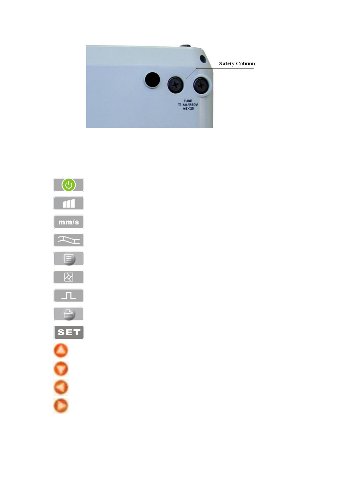
Bottom view
5.2 Key Definition
Function key: This key turns EKG312T on or off.
Function key: This key is used to adjust gain.
Function key: This key is used to adjust paper speed.
Function key: This key is used to select filter function.
Function key:Menu key.
Function key: This key is used to switch printing modes.
Function key: 1mV calibration.
Function key: This key is used to print.
Function key: System menu.
Direction key: Up
Direction key: Down
Direction key: Left
Direction key: Right
5.3 Indicator light definition

10
When green, the light indicates EKG312T is powered by AC supply; while red and green, it
indicates the battery is charging.
Powering on indicator light.

11
Chapter6 Notes Before Operation
6.1 To use EKG312T safely and effectively, you should read the user manual carefully before
operation.
6.2 Notes for installation and storage:
1) EKG312T shall be keep away from high voltage cable, X-ray equipment, ultrasound device
or electrotherapeutics machine,etc.
2) Avoid using and storing EKG312T in the places with high air pressure, temperature and
humidity beyond standard, bad ventilation, excessive dust or salt-alkali gas and chemical
medicine.
6.3 EKG312T should be put on flat place and taken and put lightly when moved. Avoid too strong
vibration and shock.
6.4 AC frequency and voltage value should be in accordance with the requirements to ensure
enough current capacity.
6.5 Please place EKG312T indoor where it is easy to be grounded. Do not connect the patient and
the cables with other conductors including ground or beds which can be conducted well with
ground.
6.6 Clean the lead cables with water and soap, and sterilize with ethanol and aldehyde base.

12
Chapter7 Preparations Before Operation
7.1 Ensure EKG312T is grounded and all the cables are connected reliably.
7.2 Ensure the electrodes, directly connected with patient, are placed correct and reliable.
7.3 If you have selected to purchase UPS, check whether the output voltage is normal or not.
7.4 Electric gel coat should be separated and chest electrodes should not connect with each other ,
so as to avoid short circuit.
7.5 AC power cable should not enlace with ECG lead cables.

13
Chapter8 Notes During Operation
8.1 Pay attention to the patient and device status at any moment.
8.2 Patient and device can only be connected through ECG lead cables.
8.3 Keep close observation of the patient and device to make sure they are still during operation.
8.4 Turn off EKG312T after using.
8.5 Disconect the power, and remove the ECG lead cables gently without strong force.
8.6 Properly keep EKG312T and its accessories for operation next time.
8.7 Recording Paper Loading
Recording paper loading sketch map
1) EKG312T adopts high-speed thermal recording paper with the specification of
80mm(W)×20m(L).
2) Open the cover of paper cabinet, take out the paper axis and install it into recording paper
then load them at the proper position inside the cabinet as showed in the figure above.
3) Close the cover of paper carriage. It's recommended to leave 2cm paper outside.

14
Chapter9 Usage of Recording Paper
9.1 When recording EKG312T will stop paper trace in case of paper lack, and the LCD screen will
display as the figure below to prompt paper lack.
9.2 It is recommended to use the thermal recording paper specified by our company to ensure
ECG waveforms of good effect. Bad recording paper will result in unclear ECG waveforms,
fading or unsmooth paper trace, etc, even pricking up the device's worn up and shortening the
service cycle of such important components as printerhead. Please consult your franchiser or our
company for purchasing this recording paper.
9.3 High temperature, humidity or direct sunniness may all be the causes for recording paper
failure.The paper ,which will not be used for long, shall be stored in place cool, dry and dark.
9.4 Substance may contaminate surface of the recording paper:
Gel, glue, and half-dry diazo compound copy paper including their organic solvent.
9.5 Substance may cause the waveforms to disappear:
Soft PVC folders, plastic,etc; demagnetization machine and tape containing plasticizer;
some fluorescence ink pen and stamp-pad ink,etc.

15
Chapter10 Electrode Placement
It is better to attach chest electrodes first, then the limb electrodes.
10.1 Chest Electrode Placement( See the figure below)
Attach the chest electrodes to the locations as following:
V1: Fourth inter-costal space at right border of sternum.
V2: Fourth inter-costal space at left border of sternum.
V3: Midway between V2 and V4.
V4: Fifth inter-costal space at left mid-clavicular line.
V5: Left anterior axillary line at the horizontal lever of V4.
V6: Left mid-axillary line at the horizontal lever of V4.
Clean the skin where chest electrodes are to be attached with alcohol, then apply ECG cream to
here around 25mm in diameter and to the edge of chest electrodes, then press and attach the
electrodes to the positions from V1-V6.
Note:Keep in mind that the electrodes’ coming into contact with each other or cream’s
overlap from one position to another is not allowed to avoid short circuit.
10.2 Limb Electrode Attachment
Electrodes should be placed on the soft skin of hands and feet. Clean all the limb electrodes and
the positions where limb electrodes are to be attached with alcohol before applying ECG cream to
them, then firmly attach the electrodes to the positions.
Note: Screw tightly the knob of ECGcable's plug after it is inserted to the ECG connector.
10.3 Check-List for Electrodes and ECG cables

16
Electrode Location
Electrode Symbol
Plug No.
Right Arm
RA/R
9
Left Arm
LA/L
l0
Left Leg
LL/F
11
Right Leg
RL/N
14
Chest 1
Vl/Cl
12
Chest 2
V2/C2
1
Chest 3
V3/C3
2
Chest 4
V4/C4
3
Chest 5
V5/C5
4
Chest 6
V6/C6
5
Notes:
You had better ensure to attach the lead cables in power off status.
If there is no ECG waveforms for long, please confirm whether the electrodes are in
good contact with skin or not, then press start button several times, and each time
pressing start key will block for several ms.
When attached, the electrodes must be daubed with electric gel.

17
Chapter11 Grounding and Power Connection of Device
Make sure power supply is off, plug the 3-line connector in the device, the other end into power
receptacle which should be center grounded. It is prohibited to use water pipe or other pipeline as
grounding cable. Properly grounded can ensure the safety and reduce the interference of AC and
other electromagnetic wave.
Table of contents
Other Meditech Medical Equipment manuals


Popular Medical Equipment manuals by other brands

Otto Bock
Otto Bock AxonRotation 9S503 Instructions for use

Hitachi
Hitachi S121 instruction manual

Mindray
Mindray PM-60Vet Operator's manual

New Life Radiology
New Life Radiology Evostyle N.G. Installation and user manual

Force Dimension
Force Dimension lambda.7 haptic device user manual

DJO Global
DJO Global DONJOY ULTRASLING IV ER Application guide


