Medva MAG-NET 800S User manual

1
MAG·NET 800S-1000S-1300S
INSTRUCTION MANUAL
V2-05/19

2
OPEN
A- Guide length
B- Door track
C- 50-mm minimum overhang guide
D- Cover-gap distance
E- Gap height
F- Door-floor distance 8 to 12 mm
G- Gap width
H- Door width
J- Door height
S1- Door overlap
S2- Closure door overlap
S3- Upper door overlap
1- Front cover
2- Clamp cover
3- Mounting brackets
4- Glass door
5- Operator carriage
6- Clamp
7- Wall
MAG·NET800 = 1711mm
MAG·NET1000 = 2111mm
MAG·NET1300 = 2711mm
MAG·NET800 = 797mm
MAG·NET1000 = 996mm
MAG·NET1300 = 1295mm
* Dotted line is gap
COMPONENTS AND GENERAL MEASUREMENTS
GLASS PANEL CALCULATION
Glass door width (H) = S1+S2+G
Glass door height (J) = S3+E-F
V2 11/17
MAG·NET800
MAG·NET1000
MAG·NET1300
MAG·NET800
MAG·NET1000
MAG·NET1300
COMPONENTS AND GENERAL MEASUREMENTS

3
OPEN
A- Guide length
B- Door track
C- 50-mm minimum overhang guide
D- Cover-gap distance
E- Gap height
F- Door-floor distance 8 to 12 mm
G- Gap width
H- Door width
J- Door height
S1- Door overlap
S2- Closure door overlap
S3- Upper door overlap
1- Front cover
2- Clamp cover
3- Mounting brackets
4- Glass door
5- Operator carriage
6- Clamp
7- Wall
MAG·NET800 = 1711mm
MAG·NET1000 = 2111mm
MAG·NET1300 = 2711mm
MAG·NET800 = 797mm
MAG·NET1000 = 996mm
MAG·NET1300 = 1295mm
* Dotted line is gap
COMPONENTS AND GENERAL MEASUREMENTS
GLASS PANEL CALCULATION
Glass door width (H) = S1+S2+G
Glass door height (J) = S3+E-F
V2 11/17
ROOF ATTACHMENT CALCULATION
Door height(J)= R-(105+F)
F-
J-
K-
N-
P-
Q-
R-
S-
U-
Door-oor distance 8 to12 mm
Glass door height.
Ceiling-door constant.
Carriage-clamp distance.
Cover to drill hole distance.
Ceiling-clamp cover total height.
Ceiling-oor distance.
Glass width.
Glass to cover distance.
5
GLASS DOOR CLAMPS
WOODEN DOOR
ROOF ATTACHMENT CALCULATION

4
ROOF INSTALLATION

5
BEAM POSITION PROFILE CALCULATION
GLASS DOOR CLAMPSWOODEN DOOR
BEAM PROFILE POSITION (R) = F+J+35
F-
J-
K-
L-
M-
N-
P-
Q-
R-
S-
T-
U-
S3-
Door-oor distance 8 to 12 mm.
Door height.
Constant beam prole-door.
Clamp height.
Cover height.
Carriage-clamp distance.
Cover width.
Cover-clamp cover total height.
Beam prole-oor height.
Wooden door width.
Carriage-wooden door distance.
Wall-glass door separation.
Door overlap at upper height.
65
65
S
BEAM PROFILE POSITION CALCULATION

6
WALL ATTACHMENT CALCULATION
GLASS DOOR CLAMPSWOODEN DOOR
DRILL HOLE POSITION (R) = F+J+100
DOOR ACCORDING TO DRILL HOLE (J) = R-(F+100)
JJ-
K-
L-
M-
N-
P-
Q-
S-
T-
U-
S3-
Door-oor distance 8 to 12 mm.
Door height.
Constant beam prole-door.
Clamp height.
Cover height.
Carriage-clamp distance.
Cover width.
Cover-clamp cover total height.
Wooden-glass door width.
Carriage-wooden door distance.
Wall-glass door separation.
Door overlap at upper height.
s
R- Cover-door total distance.
F-
WALL ATTACHMENT CALCULATION

7
WALL ATTACHMENT CALCULATION
GLASS DOOR CLAMPSWOODEN DOOR
DRILL HOLE POSITION (R) = F+J+100
DOOR ACCORDING TO DRILL HOLE (J) = R-(F+100)
JJ-
K-
L-
M-
N-
P-
Q-
S-
T-
U-
S3-
Door-oor distance 8 to 12 mm.
Door height.
Constant beam prole-door.
Clamp height.
Cover height.
Carriage-clamp distance.
Cover width.
Cover-clamp cover total height.
Wooden-glass door width.
Carriage-wooden door distance.
Wall-glass door separation.
Door overlap at upper height.
s
R- Cover-door total distance.
F-
ATTACHMENT CALCULATION

8
START OPERATION
1. Before connecng the power, verify manually that the door slides without obstacles or fricon. The limit
switches are always adjusted with the mechanical limit switches of the operator, never with the door.
2. Connect the 24-Vdc output of the power supply to the DC input of the electronic control box.
3. Connect the power supply to the AC power outlet.
4. Once the power supply is connected to the power outlet, the green LED located on the electronic control
will light up, and the motor will begin the automac adjustment of the door.
AUTOMATIC ADJUSTMENT
- Factory automac adjustment: The door will make 5 movements (closure, opening, closure, opening and
closure).
If we allow the door to make the 5 automac-adjustment movements without touching the panel during any
of the manoeuvres, the door will be congured to the factory sengs:
• 5 seconds self-closure.
• LOW ENERGY mode acvated.
- Advanced automac adjustment: The door will make 5 movements (closure, opening, closure, opening and
closure).
1. The door will move in learning speed at closure, unl reaching the closed door stopper.
At this moment (closed door) and prevenng the door from starng the opening maneuver for 4 seconds,
the LOW ENERGY opon will be acvated / deacvated. Aer 4 seconds, release the door so that it opens in
learning.
2. The door will move at learning speed on opening, unl reaching the open door stopper.
3. Closure: at this me, the red LED of the driver will indicate the level of speed/weight to be applied to close
the panel, according to the eort needed to move it (panel weight).
LOW ENERGY: This consists of operaon with
low kinec-energy movements to prevent
damage to users who use the door without
safety protecons.

9
a. 1 LED ash → low-weight panel (< 30 kg).
b. 2 LED ashes → low-to-medium-weight panel (> 30 kg and < 50 kg).
c. 3 LED ashes → medium-to-high-weight panel (> 50 kg and < 70 kg).
d. 4 LED ashes → high-weight panel (> 70 kg and < 90 kg).
**If the weight detected is over 90 kg, the door will become blocked. Flashing red LED.
4. Opening: at this me, the red LED of the driver will indicate the level of speed/weight to be applied to open
the panel, according to the eort needed to move it (panel weight).
5. Once the 4th movement is complete, the door will wait for a maximum of 10 s to set the SELF-CLOSURE
me in AUTO mode. Move the door, PUSH&GO to close, to determine this me. If the PUSH&GO closure
manoeuvre is not carried out within the 10 seconds, the door will automacally close and set the me to 5
seconds by default.
**IMPORTANT: THE PANEL MUST WEIGH AT LEAST 15 KG FOR THE OPERATOR TO FUNCTION
PROPERLY (smooth, sleek movements).
OPERATING MODE
The door has 2 operang modes:
1. PUSH&GO: The door will open with the PUSH&GO command, and will automacally close aer the me set
in automac adjustment step 5 has elapsed.
2. AUTO: This opon is available if the oponal TC MAG·NET S card is installed (95372.K1).
The door will open in PUSH&GO mode, with radars or with buons connected to the terminal of the
TC MAG·NET S card and will automacally close aer the me set in automac adjustment step 5 has elapsed.
“OPEN DOOR” MODE
Open the door, and once the opening manoeuvre is complete (before it starts to close, i.e. when the door is
fully open), hold the door for the number of seconds set in automac adjustment step 5, prevenng it from
carrying out the closure manoeuvre. The driver will detect that we want to acvate the OPEN DOOR mode.
To return to the PUSH&GO/AUTO mode, simply push lightly (PUSH&GO) to close it and the driver will return
to its automac mode.

10
CONNECTION EXAMPLES
Combined detector connecon
PRIMETEC
Touchless switch connecon
CLEANSWITCH
Power -
Power +
COM relay
NC relay
NO relay
White
Red
Green
Gray
Blue
1
2
3
4
5
GND
+V
11/21
12/22

11
Declaración de Conformidad
Nombre o razón social: Medva Mecanismos del Valles, S.L.
Dirección: C/ Natación 26-28 Pol. Ind. Can Roses - 08191 Rubí
Documento de identicación (CIF/NIF): B-60528015
C E R T I F I C A :
Que el operador MAG·NET se ha fabricado para incorporarse en una máquina o para ser ensamblado con otras maquinarias
para fabricar una máquina de conformidad con la Directiva 2006/42/CE:
Cumple con los requisitos esenciales de seguridad de las siguientes directivas CEE.
Asimismo, declara que no está permitido poner en funcionamiento la maquinaria hasta que la máquina en la que deberá in-
corporarse o de la cual será un componente se haya identicado y se haya declarado su conformidad con las condiciones de la
Directiva 2006/42/CEE y posteriores modicaciones.
Certicación del laboratorio; Compatibilidad Electromagnética (Emisiones y radiaciones).
ENSAYOS Y MEDIDAS SOLICITADAS:
* Seguridad Eléctrica.
* Compatibilidad Electromagnética / Emisiones.
* Compatibilidad Electromagnética / Inmunidad.
DIRECTIVAS:
2014/30/UE Compatibilidad Electromagnética.
2014/35/UE Baja Tensión.
NORMAS:
UNE-EN 60335-1:2012+A11:2014+AC:2014 Seguridad de los aparatos electrodomésticos y análogos. Parte 1: Requisitos Generales (Parcial).
UNE-EN 61000-6-1:2007+A1:2012 (IEC 61000-6-1:2005) CEM, Genérica Inmunidad: Residencial e Ind. Ligera.
UNE-EN 61000-6-3:2007+A1:2012 (IEC 61000-6-3:2005) CEM, Genérica Emisiones: Residencial e Ind. Ligera.
UNE-EN 55014-1:2008+E:2009+A1:2009+A2:2012 (EN5514-1:2006) Electrodomésticos, herramientas y aparatos análogos EMI.
UNE-EN 55014-2:2015 Electrodomésticos, Herramientas eléctricas y análogos (INMUNIDAD).
UNE-EN 55022:2011+AC:2012 Equipos de tecnología de la información. Perturbaciones. Clase B.
UNE-EN 55024:2011+A1:2015 Inmunidad equipos tecnología de la información.
UNE-EN 55032:2016+AC:2016-07 Equipos multimedia. Perturbaciones. Clase B.
UNE-EN 60669-2-5:2017 Requisitos particulares interruptores electrónicos (HBES).
Certicación de seguridad en baja tensión de aparatos domésticos:
EN 60335-1 Aparatos electrodomésticos y análogos. Seguridad. Parte 1: Requisitos generales.
EN 60335-2-103 Aparatos electrodomésticos y análogos. Seguridad. Parte 2-103: Requisitos particulares para accionadores de portones, puertas y ventanas.
Certicación de MEDVA Mecanismos del Vallés, S.L.; Parte de puertas automáticas:
EN 16005 Puertas automáticas peatonales. Seguridad de uso. Requisitos y métodos de ensayo.
Número de matrícula: Gerente
-Ponemos en la máquina la marca de conformidad
ANTONIO ORANTES ZAMBRANO

12
+34 93 588 50 37
C/Natación, 26-28, nave 5
Polígono Industrial Can Roses
08191 RUBÍ (Barcelona) - Spain
+34 93 588 35 03
MEDVA Mecanismos del Vallés, S.L.
www.medva.es
®
This manual suits for next models
2
Table of contents
Popular Door Opening System manuals by other brands

Schartec
Schartec Prime 600 Installation and operating instructions
Helm
Helm GT-L 50 installation instructions
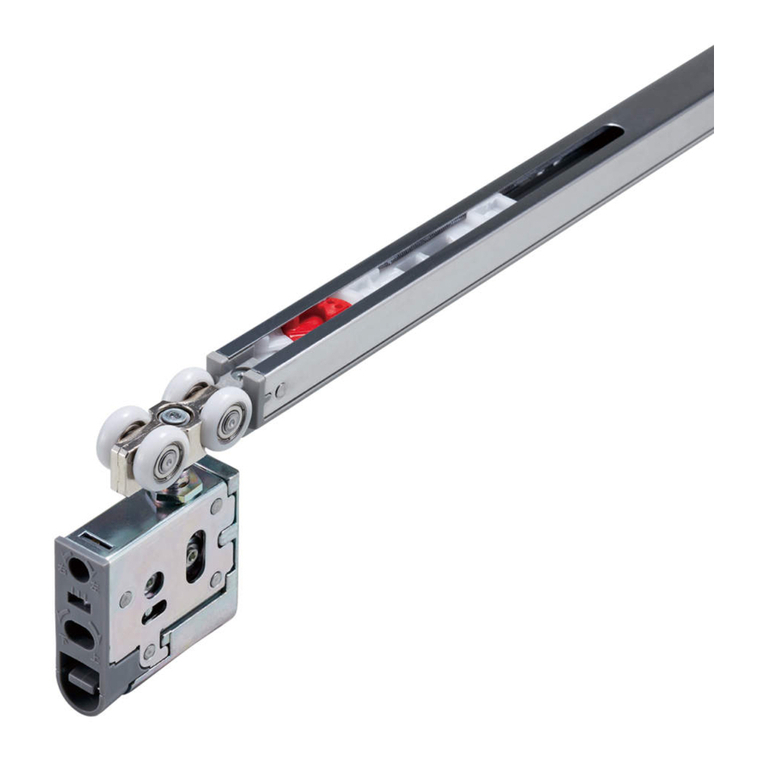
SUGATSUNE
SUGATSUNE LAMP FD35EV installation manual
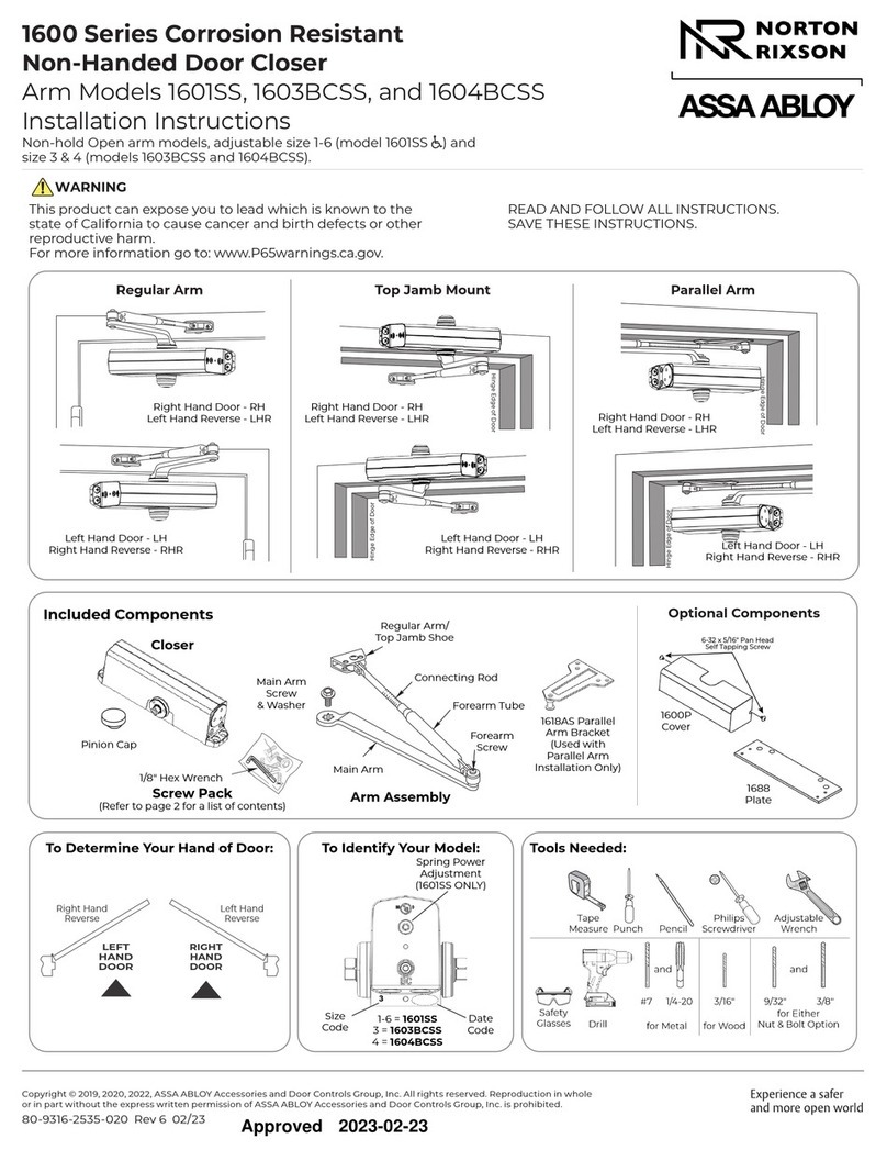
Assa Abloy
Assa Abloy NORTON RIXSON 1600 Series installation instructions
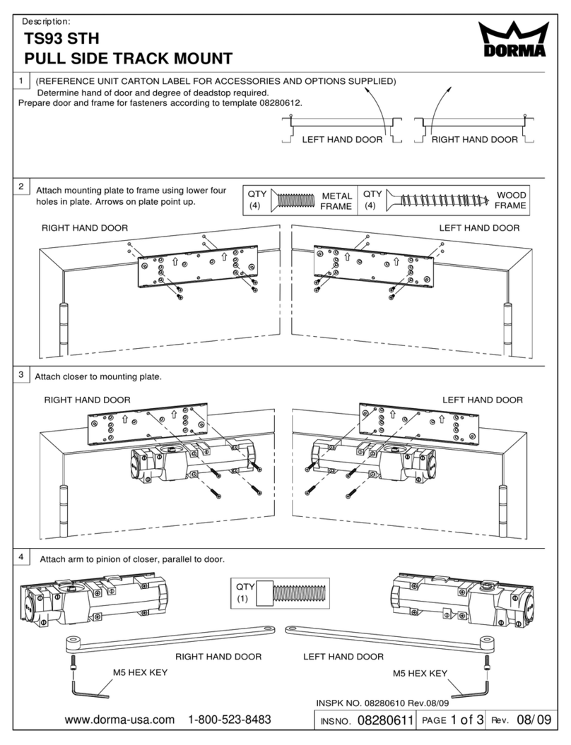
Dorma
Dorma TS93 Series quick start guide

Häfele
Häfele Finetta Flatfront M35 FB Assembly and adjustments

Woodhaven
Woodhaven 4516 quick start guide
Rittal
Rittal VX IT 7030.262 Assembly and operating instructions
GEZE
GEZE TS 5000 ECline Mounting instructions
Cal-Royal
Cal-Royal N-MR7700 Series Installation instruction
Dormakaba
Dormakaba ED100 installation instructions

ATIM
ATIM Ghost vetro 880 Assembly instructions

