SUGATSUNE LAMP FD35EV User manual

1
Thank you for using our product. Before installation, please read this manual thoroughly to ensure correct installation.
Please keep this manual at hand for future reference.
FD35EV SLIDING DOOR SYSTEM Installation Manual
Recessed Mount Roller, Two-Way Soft Close
Part No.FD35EVDHCP
●This is a parts set for a sliding door system for residential &
commercial use.
●
7KHGRRUFORVHVLQVRIWPRWLRQVWHSV¿UVWVORZWKHQIDVW
and opens with 1 step soft motion.
●The door can be installed without the use of tools.
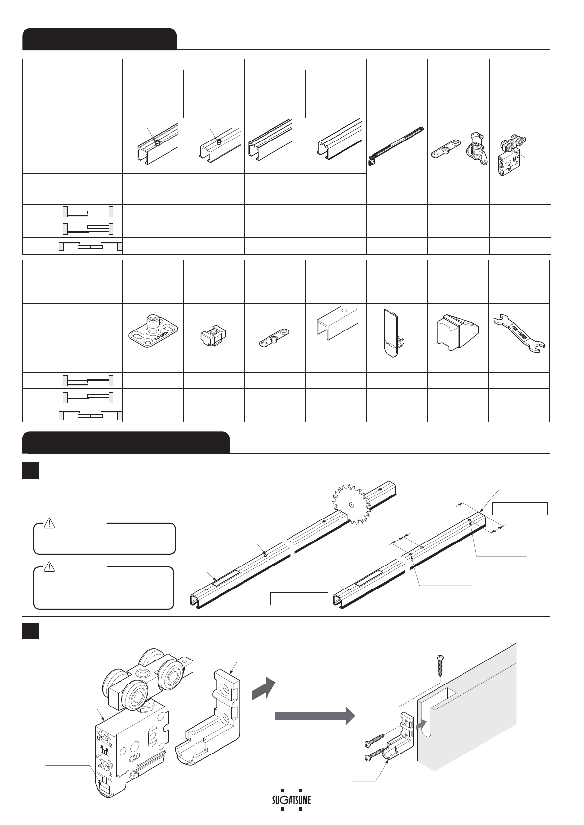
ABOUT THE PRODUCT
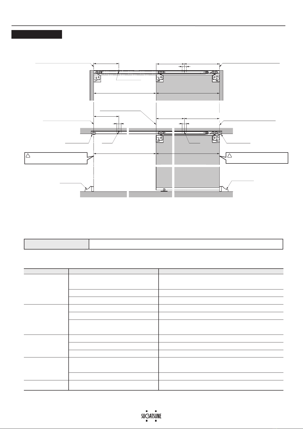
Door Height Max.2400 mm 2401 - 2700 mm
Door width 590 - 1200 mm 700 - 1200 mm
Min. Door thickness 24 mm
Max. Door weight 35 kg※1/door
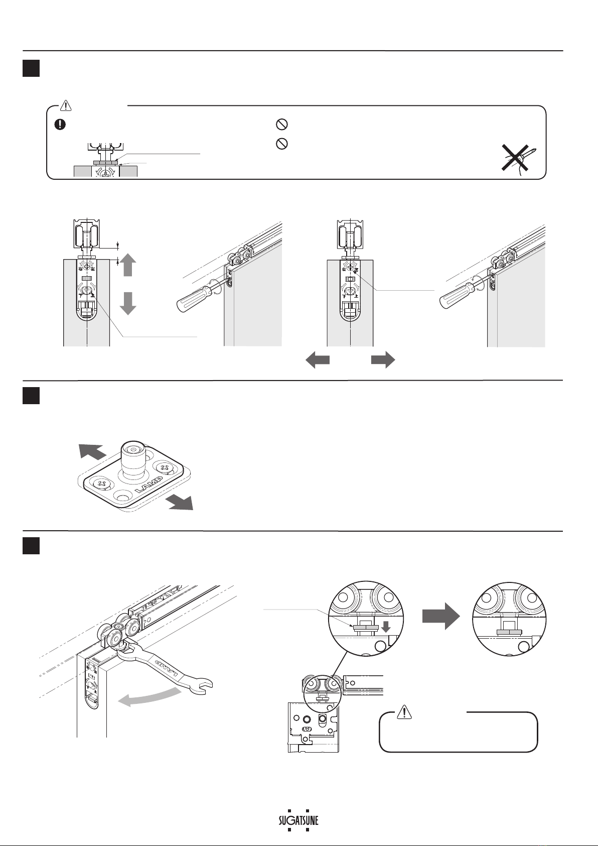
Vertical adjustment
3 mm upward, 4 mm downward
Depth adjustment
±2 mm
・
The closing speed of the soft closing type door may change depending on
the ambient temperature, operating method or installation quality.
・Recommended ambient temperature range is 5 to 40 ℃.
※1When using a light weight door, you may feel the resistance of
the soft closer when opening the door.
SPECIFICATIONS
FOR YOUR SAFETY AND CORRECT INSTALLATION
Prohibited
Warning
Caution Required
Meaning of symbols
WARNING: If not followed, death or serious injury may result.
Caution: If not followed injury or damage may result.
7KLVSURGXFWVKRXOGEHLQVWDOOHGE\DTXDOL¿HGSHUVRQLQDFFRUGDQFHZLWKWKLVPDQXDO,ILWLVQRWLQVWDOOHGFRUUHFWO\WKHGRRU
may fall and cause injury.
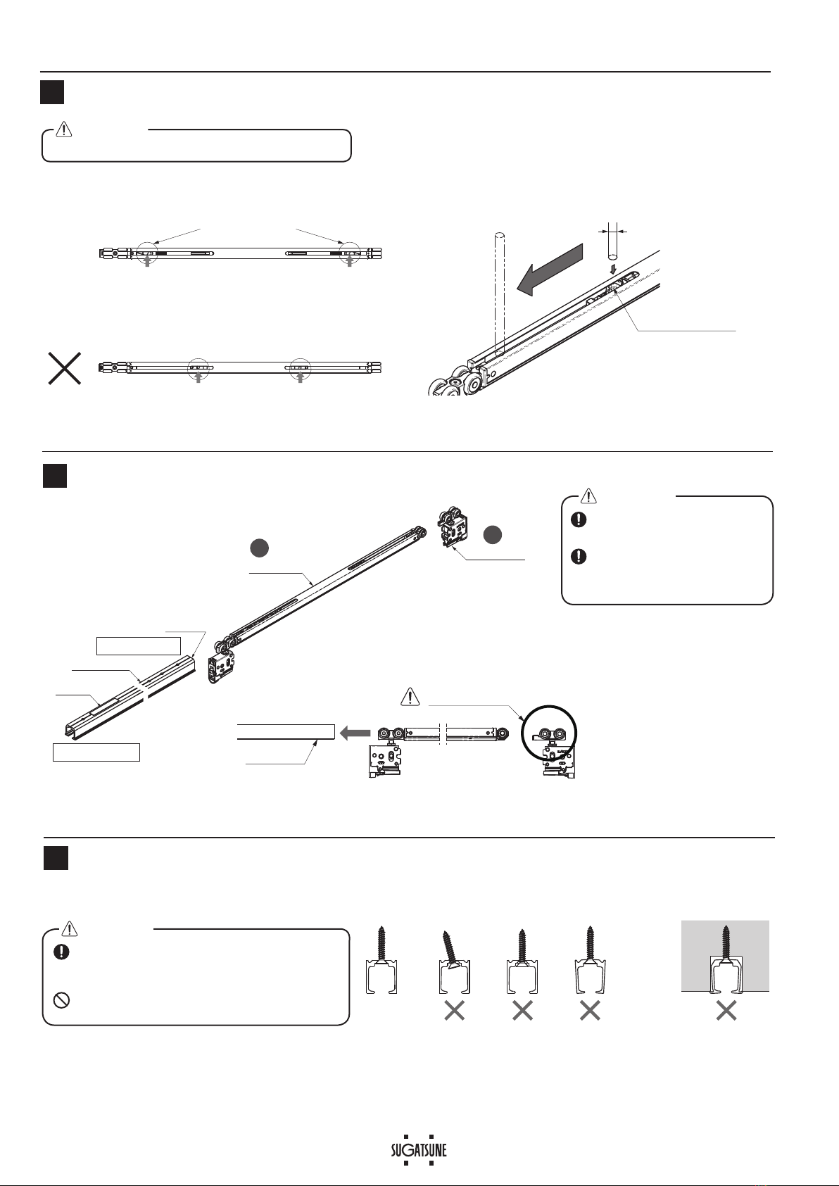
3URYLGHDIUDPHWKDWFDQZLWKVWDQGWKHZHLJKWDQGLPSDFWRIRSHQLQJDQGFORVLQJWKHGRRU%HVXUHWRXVHWKHVSHFL¿HG
VFUHZVDQGWLJKWHQWKHPVHFXUHO\,IWKHPRXQWLQJVWUHQJWKLVLQVXI¿FLHQWWKHGRRUPD\IDOODQGFDXVHLQMXU\
'RQRWXVHWKLVSURGXFWIRUDQ\RWKHUSXUSRVHRUZLWKGRRUVWKDWDUHRXWVLGHWKHVSHFL¿FDWLRQVRIWKLVPDQXDO
Do not disassemble or modify any parts other than those described in this document.
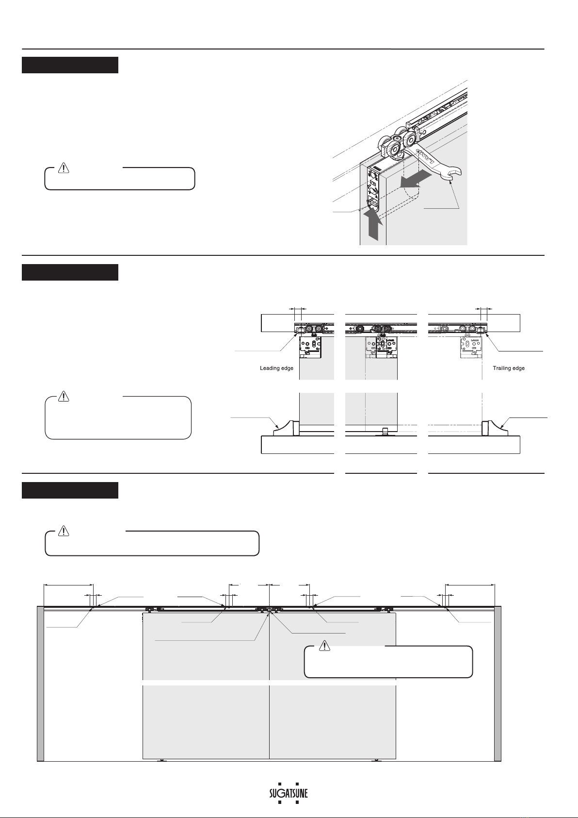
)ROORZWKHVSHFL¿HGGLPHQVLRQVVSHFL¿FDWLRQVDQGDOLJQPHQWRIWKHGRRUDQGIUDPH:DUSLQJWLOWLQJRUWZLVWLQJRIWKH
frame or door may cause failure.
If cutting any parts, make sure to remove any burrs before installation. Also check the upper track for any left-over burrs or
scraps and remove these.
7KLVSURGXFWLVDSDUWIRUDUFKLWHFWXUDO¿WWLQJV$IWHULQVWDOODWLRQSOHDVHFKHFNWKHIXQFWLRQDQGVDIHW\RIWKH¿QDOSURGXFW
Please inform the end user how to use the product safely.
0DNHVXUHWRFKHFNWKHVFUHZVIRUVODFNDWUHJXODULQWHUYDOVRQHPRQWKIURP¿UVWXVDJHKDOID\HDUDQGWKHQRQHWLPH
every year is recommended).

2
No. ① ② ③④⑤
Name
Upper track
for soft-closing
(surface mount)
Upper track
for soft-closing
(recessed mount)
Upper track for
standard sliding
(surface mount)
Upper track for
standard sliding
(recessed mount)
Soft closer
(two-way) Trigger, Jig Upper roller
Item No.
FD35EV-TRM-SC FD35EV-TRH-SC
FD35EV-TRM FD35EV-TRH
FD35EV-WRH-DSC
FD35EV-TRG
FD35EV-TRJ
FD35EV-WRH-N
Item
Flat head tapping screw
3.8×40・・・・・・・3 pcs
Countersunk head tapping screw
4×30・・・・・・・・・2 pcs
Flat head tapping screw
3.8×40・・・・・・・3 pcs
Accessories
Hole pitch
:300 mm
Pitch end :30 mm
Recommended screw:Countersunk head tapping screw 3.5×25
Use the track for standard sliding for inline sliding
Hole pitch :300 mm
Pitch end :30 mm
Recommended screw:Countersunk head tapping screw 3.5×25
Single sliding
either one −1 pc 1 pc 1 pc
Double sliding
either one −2 pcs 2 pcs 2 pcs
In line sliding
−either one 2 pcs 2 pcs 2 pcs
No. ⑥⑦⑧⑨⑩⑪⑫
Name Floor guide Bumper block Trigger Door guide track Cover cap Door stopper Spanner
wrench
Item No. FD50-BGR18 FD35EV-HBB FD35EV-TRG
FD30-HBRT1500SIL
FD50-WRH-CP
FD30-HTKY FD30-FSP
Item
Thickness: 2 mm
Bind head tapping screw
4×30・・・・・・・・・3 pcs
Hole pitch
:250 mm
Pitch end :30 mm
Recommended screw:
Countersunk head tapping screw 4×20
Countersunk head tapping screw
4×20・・・・・・・・・・・・・・・・・・ 4 pcs
Single sliding
1 pc −−
1 pc 2 pcs −−
Double sliding
2 pcs −−
2 pcs 4 pcs −−
In line sliding
2 pcs 1 pc 2 pcs 2 pcs 4 pcs −−
Trigger
Nut
Trigger
Trigger Jig
COMPONENT PARTS This describes installation of a single sliding door.
INSTALLATION PROCEDURE
1
Cutting Track and Hole Drilling on Upper track
The method of calculating the trigger mounting
position is described on the last page of Appendix 4.
(In this manual, a single sliding door is used as an example.)
Preparation of Mounting Parts
2
Do not cut trigger side (with sticker)
of upper track.
When cutting, reinforce the track
to prevent deformation at the cut
section.
CAUTION
CAUTION
Casing
Hole drillingCutting
Sticker
Trigger
Cut end
2×I4.5
(for trigger fixing)
※2[ ]: When Cover cap ⑩(option) is used.
I4.5 I7.8 CSK
(for track fixing)
30
Door width - 376
[Door width - 378 ]※2
30
Leading edge
Trailing edge
❶
❷
Main unit
Pull out casing
Pull up lever

3
Install as shown
Upper track
9HUL¿FDWLRQ%HIRUH,QVWDOOLQJ6RIW&ORVHU
3
Mounting of Upper Track
5(Recommended screw: Countersunk head tapping screw 3.5x25)
looseninclined
overtightened
deeper groove
OK
Be careful not to overtighten the screws and screw
heads protruding on upper track.
It may cause deformation of track or damage of
soft closer.
CAUTION
4Inserting Parts into Upper Track
Insert the parts in order from ❶to ❷with
care of direction.
12
Remove any dirt or aluminum
chips from the track.
Tape around rollers and upper
track to prevent the inserted
parts from falling.
CAUTION
:LWKRXWYHUL¿FDWLRQWKHVHOIFORVLQJIHDWXUHPD\IDLO
CAUTION
Soft closer
12
Upper track
Sticker
Cut end
Upper roller
Leading edge
Trailing edge
Correct set position
Improper set position
Trigger catcher
(Red colored part)
Correct set position
OK
If the trigger position is wrong, pull back the trigger
catcher to the correct position using a 6mm diameter
round bar.
Trigger catcher
(Red colored part)
I6

4
Screws
Screwdriver (+)
90°
Tri
gg
er assembl
y
OK
Out of straig
h
Correct installa
t
Trigger
Jig
2×I4.5
30
Correct installation
Out of straight
90°
OK
Fastening of Trigger
6
Fasten trigger to the hole made during procedure with provided screws.
The jig makes it easy to install the trigger.
❶Assemble trigger to jig. ❷Align trigger with
the holes.
❸Turn the jig 90゚DQG¿[
the trigger.
❹Remove the jig.
❶Place a 10 mm support under the door.
❷While holding the door, place the groove under the door
RQWKHSURWUXGLQJSDUWRIWKHÀRRUJXLGH
Support 10mm
(To be removed
after hanging)
protruding part
⑥
Floor guide
Lever
Casing
Main unit
CLICK
Floor guide
44
18
7
Mounting of Floor Guide Temporarily
Hanging Door
8
3RVLWLRQÀRRUJXLGHMXVWEHORZWKHFHQWHURIWKH
upper track.
Temporarily fasten through the
slotted holes with the provided
screws.
❶
❷
❸9HUL¿FDWLRQRI6RIW&ORVHU2SHUDWLRQ
●Starting point of soft
-
close.
Leading edge : approx.
100
mm before closed position.
Trigger edge : approx.
50
mm before closed position.
Verify that the main unit is not dislocated from the
casing, either of the door ends.
CAUTION
上
下上
下
Lever is on
the bottom.
OK

5
Jump prevention
nut
Tighten
9Adjusting the Door Position
Fastening the Jump Prevention Nut
11
Vertical adjustment range: 7 mm Depth adjustment range: 4 mm
$GMXVWWKHGRRUSDUDOOHOWRWKHXSSHUWUDFNZLWKPPRIFOHDUDQFHEHWZHHQWKHGRRUDQGÀRRU
The jump prevention nut is on the hanger bolt of the upper roller.
Tighten the nut with the provided spanner until it contacts the soft
closer.
Be sure to tighten the nut
to prevent damage.
CAUTION
Adjusting, Fastening the Floor Guide
10
If the door movement is not smooth, remove the door, then adjust the floor guide
forwards or backwards.
Adjustment range: 4 mm
Do not turn the adjustment screw beyond
adjustment range.
CAUTION
Do not turn adjustment screw beyond adjustment range.
Do not use electric screw driver.
Gap
Jump prevention nut
右
上
下
左
9
4 mm
3 mm
Vertical adjust screw
2 mm
2 mm
右
上
下
左
Depth adjustment
screw

6
④Trigger
④Trigger ⑦Bumper block
This is where the doors meet.
※3[ ] : When cover cap ⑩(option) is used.
⑧Trigger
⑧Trigger
Door width - 361
[Door width - 363]※3
Door width - 361
[Door width - 363]※3
30 2×I4.5 30
2×I4.5 30 2×I4.5 30
2×I4.5
187.5
187.5
Positions of Trigger for In Line Sliding
APPENDIX 3
Process holes according to the drawing below.
Bumper block should be inserted together
with soft closers before installing upper track.
CAUTION
Use the track for standard sliding for this application.
CAUTION
When Vertical Frame is not Used
How to remove door
⑫
Spanner
wrench
Lever
APPENDIX 1
Use a 10 mm support under the door.
Then pull out the upper roller main unit from the door while raising
the lever.
It will be easier if you slide the hanger bolt with a spanner.
Be careful not to let the door fall.
CAUTION
Bumper block
(Sold seperaterly)
Bumper block
(Sold seperaterly)
⑪
Door stopper
(Option)
⑪Door stopper
(Option)
Min.13 Min.13
APPENDIX 2
When vertical frame is not used, use the
door stopper⑪and bumper block⑦on
WKHWUDFNDQGRQWKHÀRRU
Fasten the door stopper at the location
where the door will stop. Fix the bumper
block to both the upper track ends, then
adjust it to the position where the door
closes.
The soft closer may be damaged
if door stopper and bumper block
are not installed.
CAUTION

7
361
[
363
]
※3
30
361
[
363
]
※3
187.5
Door widthAvailable opening width
187.5
Available opening width Door width
30
30
⑪
Door stopper
(Option)
! !
Door stops here when closed.
Door must be stopped by
bumper block and door stopper.
Door must be stopped by
bumper block and door stopper.
⑪
Door stopper
(Option)
Trigger Trigger
Leading edge when the
door is fully opened
Crimped trigger
Door stops here when opened.
Standard installation
Upper track installed inside door jamb
⑦
Bumper block
(Option)
※3[ ] : When cover cap ⑩(option) is used.
Door width - 361
[Door width - 363]
※3
Door width - 361
[Door width - 363]
※3
⑦
Bumper block
(Option)
Reference line for trailing edge.
(Trailing edge when the door is opened.)
Reference line for leading edge.
(Leading edge when the door is stopped.)
Special fit
(e.g.) No vertical frame and
stop with door stopper and
bumper block
Trouble Checkpoint Solution
Door stops during soft
closing
&KHFNLIGRRUERWWRPFRQWDFWVZLWKÀRRU &RQ¿UPWKDWWUDFN ¿[LQJVFUHZVDUH QRWORRVHQHG7KHQDGMXVW GRRUKHLJKW
VXFKWKDWWKHFOHDUDQFHEHWZHHQWKHGRRUERWWRPDQGÀRRULVPP
Check if upper track is set horizontally. Using a level gauge, reset upper track horizontally.
Check if mohair seal is installed. Reduce the friction between mohair and door.
No soft closing Check if trigger is installed. Install trigger to correct position.
Check if door is closed by excessive force. Do not close door by excessive force as it may damage soft closer.
The position of the trigger catcher may become
dislocated (See section.)
Slowly move the door toward the leading edge, then push the door firmly.
Repeat this action on the opposite side as well.
If it is still not improved, check the status of the trigger catcher in section .
Abnormal noise during
operation
Check if door touches other parts. Provide necessary space between the door and adjacent objects.
Check track rollers for aluminum dust. Remove the track and pull out the roller. Then, clean the roller.
Check for loose screws retaining the upper track. Tighten the screw.
Heavy door operation Check if door touches adjacent parts. Correct door position to avoid contact with other objects.
$GMXVWSRVLWLRQRIÀRRUJXLGHRUVWRSSHU
Check if the door is warped. Replace door with one that is not warped.
Door does not move. Check the track retaining screws for looseness. Retighten screws to free the roller.
Ŷ7528%/(6+227,1*
Trigger positions
APPENDIX 4
PERIODICAL INSPECTION
・Clean the inside of the track.
・Check the upper and lower space of the door. If necessary, correct the space.
Check the upper and lower space of the door. If necessary, correct the space.

8
SUGATSUNE KOGYO CO.,LTD
Tokyo, JAPAN
SUGATSUNE KOGYO (UK) LTD
Reading, UK
Phone: +44 118 9272 955
E-mail:[email protected]
SUGATSUNE EUROPE GmbH
Dusseldorf, GERMANY
Phone: +49 211 53812900
E-mail:[email protected]
SUGATSUNE SHANGHAI Co., LTD
Shanghai, CHINA
Guangzhou, CHINA
SUGATSUNE KOGYO INDIA PRIVATE LIMITED
Mumbai, INDIA
SUGATSUNE AMERICA, INC
California, USA
Chicago, USA
Phone: +1 312 461 1081
E-mail:[email protected].
SUGATSUNE CANADA, INC.
Phone: +1 514 312 5267
E-mail:[email protected]
2020.12 0963-3
INSTALLATION DRAWING (EXAMPLE) In this manual, a single sliding door is used as an example.
※3When using cover cap When using door guide track.
Door process dimensions
See P.6 APPENDIX 2 when
door stopper
⑪
(option) is used.
CAUTION
See " APPENDIX 4 " for the position of trigger.
3
1 5
4
6
187.5
523.5
[525.5 ]※3
44
18
30
Door width - 361
[Door width - 363]※3
20
22
10
28
12
15
21
20
11 0
-0.5
9+4
-3
※3[ ] : When cover cap ⑩(option) is used.
2×I4.5
(additional)
I4.4 I7.8 CSK
(Vertical adjustment)
9+4
-3 (Vertical adjustment)
Trigger
Track
(Recessed) Track
(Surface mounted)
12
15 48
16
49※3
⑩Cover cap
(option)
51
2
⑨Door guide track
(option)
15
17
This manual suits for next models
1
Table of contents
Other SUGATSUNE Door Opening System manuals

SUGATSUNE
SUGATSUNE LAMP Lapcon SDS-210 User manual

SUGATSUNE
SUGATSUNE Aileron Lift-Assist User manual

SUGATSUNE
SUGATSUNE SDS-C301N User manual

SUGATSUNE
SUGATSUNE LAMP MonoFlat FAD Series User manual

SUGATSUNE
SUGATSUNE LAMP FD80-H User manual

SUGATSUNE
SUGATSUNE LAMP LM-80 User manual

SUGATSUNE
SUGATSUNE LAMP LL-66S User manual

SUGATSUNE
SUGATSUNE Zwei L ZL-2402 User manual

SUGATSUNE
SUGATSUNE HES2S-140-A125 User manual

SUGATSUNE
SUGATSUNE LAMP FD50-H User manual