MedVision LEONARDO HF User manual

USER
MANUAL
Simulator PS.A.HF
Adult Patient Simulator
LEONARDO HF


CONTENTS
Contents
Introduction 4
1 Setting Up 8
1.1 Simulator charge . . . . . . . . . . . . . . . . . . . . . . 8
1.2 Smartscope charging . . . . . . . . . . . . . . . . . . . 9
1.3 Defibrillator/ECG charging . . . . . . . . . . . . . . . . . 12
1.4 Attaching limb modules (trauma) . . . . . . . . . . . . . 13
1.5 Fillin in secretion fluid . . . . . . . . . . . . . . . . . . . 16
1.6 IO injections access unit change . . . . . . . . . . . . . 18
2 Startup 20
2.1 Startup sequence . . . . . . . . . . . . . . . . . . . . . 20
2.2 WiFi router setting up and connecting . . . . . . . . . . 21
2.3 Connecting the Defibrillator/ECG unit . . . . . . . . . . 26
2.4 Connecting SpO2 probe . . . . . . . . . . . . . . . . . . 32
2.5 Turning on the smartscope . . . . . . . . . . . . . . . . 33
2.6 Switching on the allinone PC (bedside monitor) . . . . 34
2.7 Connections ........................ 35
3 Scenario Constructor 37
3.1 The Scenario Constructor control bar . . . . . . . . . . . 37
3.2 Creating new scenario . . . . . . . . . . . . . . . . . . . 38
3.3 General procedure for creating a new scenario . . . . . 39
3.4 Editing and setting the scenario . . . . . . . . . . . . . . 39
3.5 Configuring scenario stages . . . . . . . . . . . . . . . . 41
1

CONTENTS
3.6 Triggers........................... 43
4 Authentication 45
5 Instructor Software main menu 47
6 Exercise selection and launch 49
6.1 Exercise selection and search . . . . . . . . . . . . . . . 51
6.2 Startup ........................... 53
7 Imitation of life processes 55
7.1 Simulatorbody ....................... 55
7.2 Respiratory system . . . . . . . . . . . . . . . . . . . . . 58
7.3 Auscultation and palpation . . . . . . . . . . . . . . . . . 59
7.4 Secretion .......................... 61
7.4.1 Tank......................... 62
7.5 IO and IV injections . . . . . . . . . . . . . . . . . . . . 62
7.6 Defibrillation and ECG . . . . . . . . . . . . . . . . . . . 64
8 Exercise menu 66
8.1 Automated scenarios. List of actions . . . . . . . . . . . 66
8.2 Patient states.Manual mode and Themes sections . . . 68
8.3 Patient state settings . . . . . . . . . . . . . . . . . . . . 69
8.4 Bedside monitor settings . . . . . . . . . . . . . . . . . . 77
8.5 ECG rhythm editing . . . . . . . . . . . . . . . . . . . . 81
8.6 CPRActivation ....................... 86
8.7 List of auscultation sounds . . . . . . . . . . . . . . . . 90
8.8 ECG graph library . . . . . . . . . . . . . . . . . . . . . 96
2

CONTENTS
9 Exercise finish 97
10 Students and study groups 99
10.1 Student account creation and settings . . . . . . . . . . 99
10.2 Study group creation and settings . . . . . . . . . . . . 101
11 Debriefing 102
11.1 Debriefing. The Exercise tab . . . . . . . . . . . . . . . 103
11.2 Debriefing. CPR tab . . . . . . . . . . . . . . . . . . . . 104
12 Safety precautions 106
13 Cleaning and maintenance 107
14 Definitions 108
15 Malfunctions 110
16 Information to be presented to the Service Centre 114
17 Questions & Answers 115
Acknowledgement table 118
3

Introduction
Introduction
The Adult Patient Simulator is a human patient sumulator of a male
adult. It was designed to meet the most difficult tasks in professional
training: vital signs, realistic feel and feedback.
Features and advantages
The patient simulator is a model of a real human. The neck and
arms have a realistic mobility in all their joints.
• The patient simulator has a visually and anatomically correct
structure similar to the human body
• The neck has realistic mobility
• The legs are mobile in the hip and knee joints repeating the
mobility of human legs joints
• The arms are mobile in the shoulder joints repeating the mobility
of human arms joints
• The skin of the patient simulator is soft, elastic and realistic in
appearance and feel
• Blinking is programmable and depends on the state of
consciousness being simulated at the moment
• Pupils automatically react to the light and reflect the current state
of consciousness (being simulated at the moment)
4

Introduction
• IO and IV injection simulation (automatic injected drug and dose
recognition)
• Noise/sound imitation:
–Lung auscultation
–Unilaterally configurable breathing sounds
–Heart sounds auscultation
–The simulator can produce sounds that mimic cough, cry
and normal breathing
• Imitation of the cardiovascular system which consists of a
cardiovascular system computer model
• The system automatically calculates the dependent variables
(blood pressure and heart rate) in response to changes in
patient condition (bleeding and intravenous infusion):
–Imitation of bilateral pulse palpation on the carotid, brachial,
radial, femoral, popliteal, posterior tibial and dorsalis pedis
arteries
–Pulse is activated when palpated
• Imitation of the respiratory system, airway and thorax:
–Spontaneous breathing imitation
–Airway (mouth, oral pharynx, larynx, esophagus and
trachea) imitation
–Ventilation of either lung generates automatic chest rise
5

Introduction
–Lung ventilation with BVM or restored spontaneous
breathing imitation returns the simulator to normal
respiratory rate
–Imitation of difficult airway for intubation
–Tongue Edema imitation
• CPR features detailed assessment:
–Compression depth
–Compression rate
–Hand positioning
–Decompression
–Ventilation volume and frequency
–Defibrillator discharge
–Defibrillator pads position
• Truetolife bedside monitor:
–Ability to set graphs, scale and alarms
–ECG printing out and defibrillation
–Imitation of drug administration and test results display
• The stomach designed based on real patient data
–Esophageal intubation with abdominal distension
• The heart designed based on real patient data
6

Introduction
–Heart ausculation is performed in five points: aortic valve,
pulmonary valve, tricuspidal valve, mitral valve and
secondary aortic area
7

1 SETTING UP
1 Setting Up
1.1 Simulator charge
• Connect the adapter cord to the simulator charger.
Figure 1.1 Charger assembly
• Remove the silicone pad on the left shoulder of the simulator.
• Insert the charger plug into the slot under the power button and
turn the plug clockwise until it clicks
8


1 SETTING UP
Figure 1.3 Power connector
• Plug the charger into a power outlet (220 V)
• Wait until the smartscope is fully charged (may take up to 3 hours)
• The smartscope running time is 5 hours, and up to 8 hours in the
standby mode
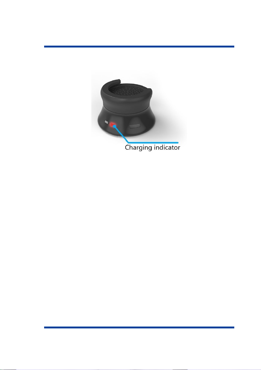
The LED located opposite to the port is used as a charge indicator
(Figure 1.4). During charging, the LED indicator is blinking red. As
soon as the battery charging is complete the LED stops blinking and
turns off.
10
1 SETTING UP
Figure 1.4 Charging indicator
11


1 SETTING UP
• Plug the charger into a power outlet (220 V)
• Wait until the simulator is fully charged (may take up to 3 hours)
• Running time is 8 hours
The Power LED is used as a charge indicator. While the unit battery
is charging, the Power LED will be blinking green. As soon as the
battery charging is complete the Power LED stops blinking and turns
off.
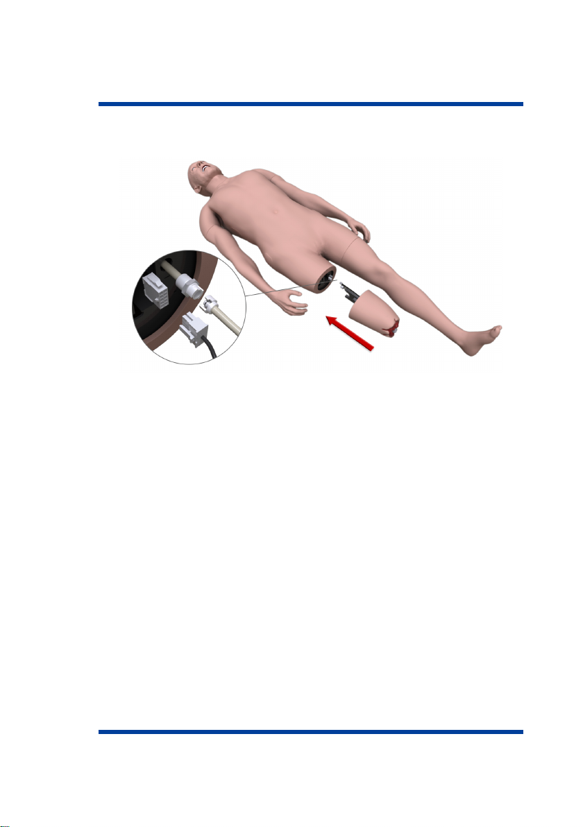
1.4 Attaching limb modules (trauma)
• Find a small hole located on the back of the thigh (for a leg) or
shoulder (for an arm)
• Insert any narrow long object such, e.g. a ballpoint pen, into the
hole and press the button located inside (until it clicks)
• Gently pull the detachable limb to allow access to the connecting
cables
• Disconnect interface connections figref Leg and carefully remove
the limb module from the internal fix
13

1 SETTING UP
Figure 1.7 Detaching limbs (leg)
• Take the trauma module figref LegConnect of the required limb
• Position the limb module following the internal mounting guides
• Connect the interface connections
14
1 SETTING UP
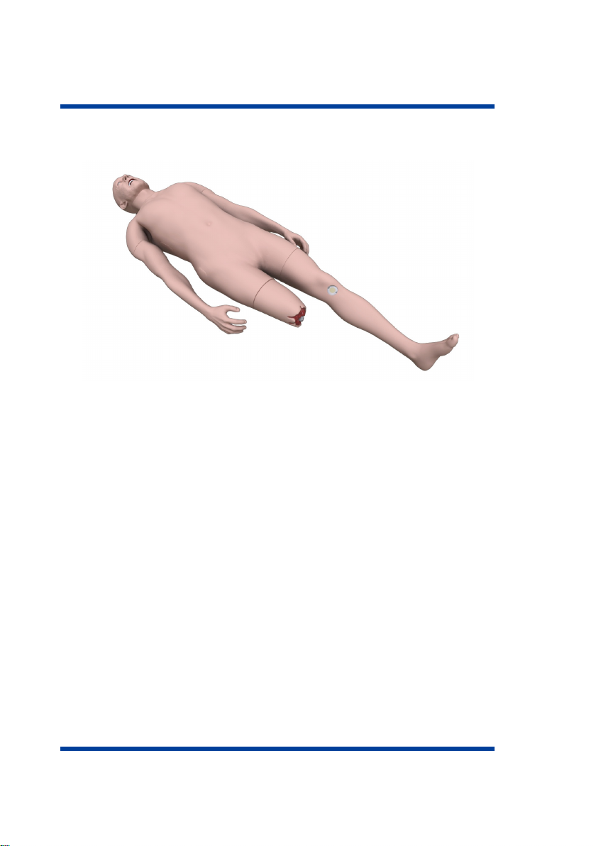
Figure 1.8 Attaching trauma modules
• Carefully, to prevent damage to the connections, push the limb
module all the way.
15
1 SETTING UP
Figure 1.9 Trauma module
Note: The trauma module is optional. Please check for the trauma
module subject to the List of Equipment.
1.5 Fillin in secretion fluid
• Remove the pad on the right (left — for blood) side of the
simulator
• Insert the hose into the «water in» port
• Connect the air hose (red) to the «air out» port and turn the lock
clockwise
• Insert the excess fluid bottle hose to the outlet port
16
Table of contents
Popular Medical Equipment manuals by other brands


Getinge
Getinge Arjohuntleigh Nimbus 3 Professional Instructions for use

Mettler Electronics
Mettler Electronics Sonicator 730 Maintenance manual

Pressalit Care
Pressalit Care R1100 Mounting instruction

Denas MS
Denas MS DENAS-T operating manual

bort medical
bort medical ActiveColor quick guide

AccuVein
AccuVein AV400 user manual


