Meeting Pod 2 Person Pod User manual


Installation Guide
2 Meeting Pod Installation Guide sales@themeetingpod.co.uk
Table of contents
-Fixings Guide, Tools & Accessories 3
-Floor Plans 4
-Installation Instructions 6
-Pod Accessories 10
-Pod Electrics: Lighting & Power 18
-Warranty: Pod & Accessories 20
-Pod Cleaning 22
-Working Together 23

Installation Guide
3 Meeting Pod Installation Guide sales@themeetingpod.co.uk
Fixings Guide
Fixing box contents
-2 x m6 x 25mm zinc plated bolts
-4 x zinc plated m6 penny washers
-8 x m6 x 20mm self tapping screws
-Pod cloth
-Pod cleaner
Tools & Accessories
-M10 ratchet socket set with spacer bar
-M10 spanner angled or flat
-Tape Measure
-Step ladder
-G Clamps x 2
-Bin liner

Installation Guide
4 Meeting Pod Installation Guide sales@themeetingpod.co.uk
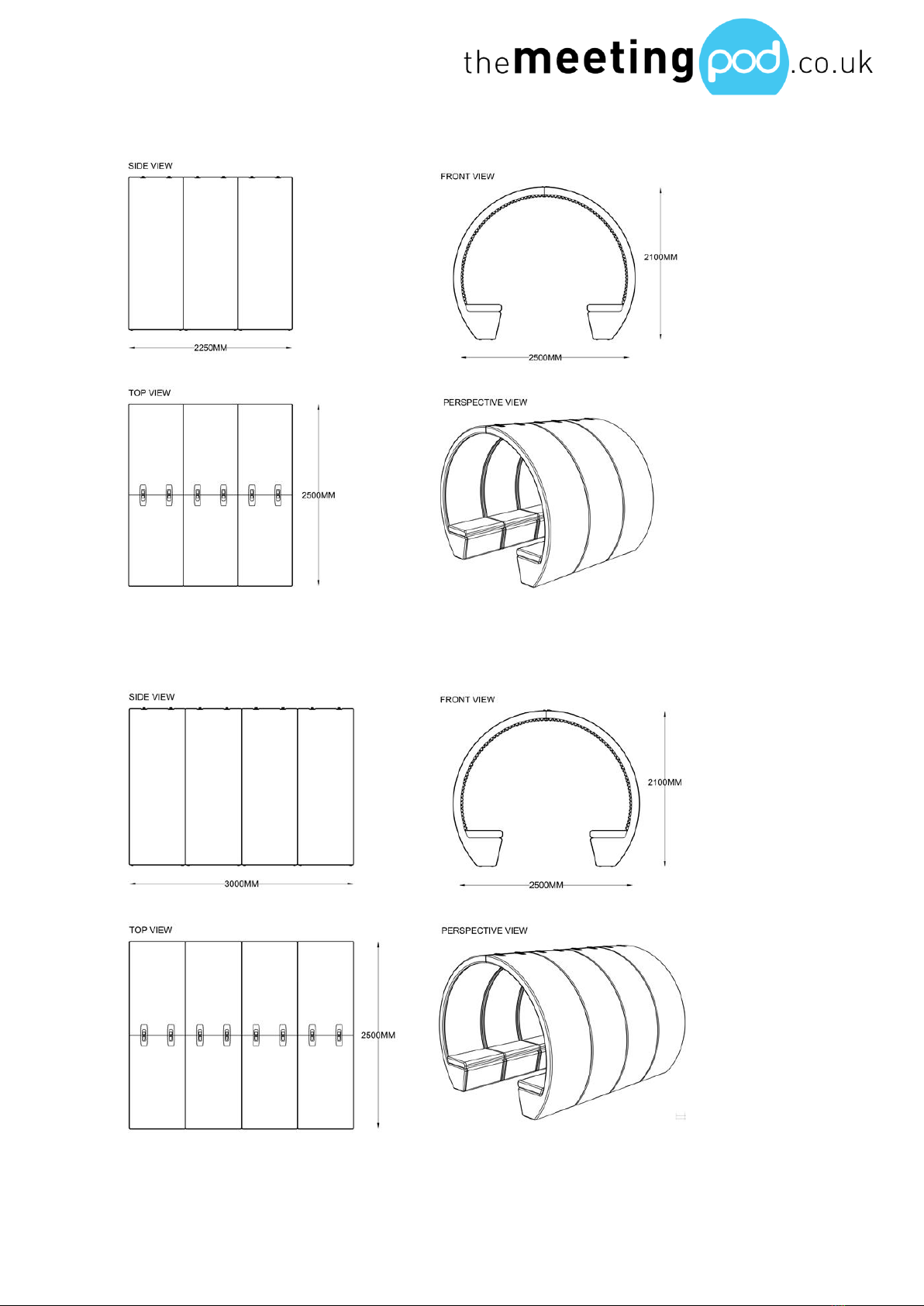
Floor Plans
2 Person Meeting Pod
4 Person Meeting Pod
Installation Guide
5 Meeting Pod Installation Guide sales@themeetingpod.co.uk
6 Person Meeting Pod
8 Person Meeting Pod
Installation Guide
6 Meeting Pod Installation Guide sales@themeetingpod.co.uk
Installation Instructions
Placement
-Lay all items flat to ensure limited damage occurs. Keep desire location
of the pods clean
-Remove all packaging. Take care when removing packaging as this
can cause damage easily
-Product code on top of the joining faces will help to locate pods
(example below)
-Segments should be placed according to floor plan
Joining
-Collect 2 x m6 25mm bolts along with 2 x m6 penny washers
-Carefully peel back the top 300mm of acoustic foam- note the foam
can rip if care is not taken
-Repeat process on all segments
Front Left
Front Right
Front Entrance
Front Right

Installation Guide
7 Meeting Pod Installation Guide sales@themeetingpod.co.uk
-The pods are designed to stay up right when left idle. To remove any
danger of segments falling clamp the products together as indicated
above, this helps the final alignment when bolting together.
-When pulling back the acoustic foam you will find two access holes in
the meeting pod lining.
-Place m6 bolts and washers through the access hole into the bolting
hole

Installation Guide
8 Meeting Pod Installation Guide sales@themeetingpod.co.uk
-Bolt through the right-hand pod
-Nut and washer through the left-hand pod
-Tighten loosely with hands and repeat this process on both holes
-Once hand tight, tighten further using a M10 socket. Hold the second
spanner on the nut end and together firmly
-Bolting alignment is now complete
Fixing down
-Tools required: 4 x 25mm coach bolts and 4 x m6 penny washers. M10
socket drive and power drill
-Remove cushions. Cushions are secured with Velcro on the underside
and the upper side of the seat moulding
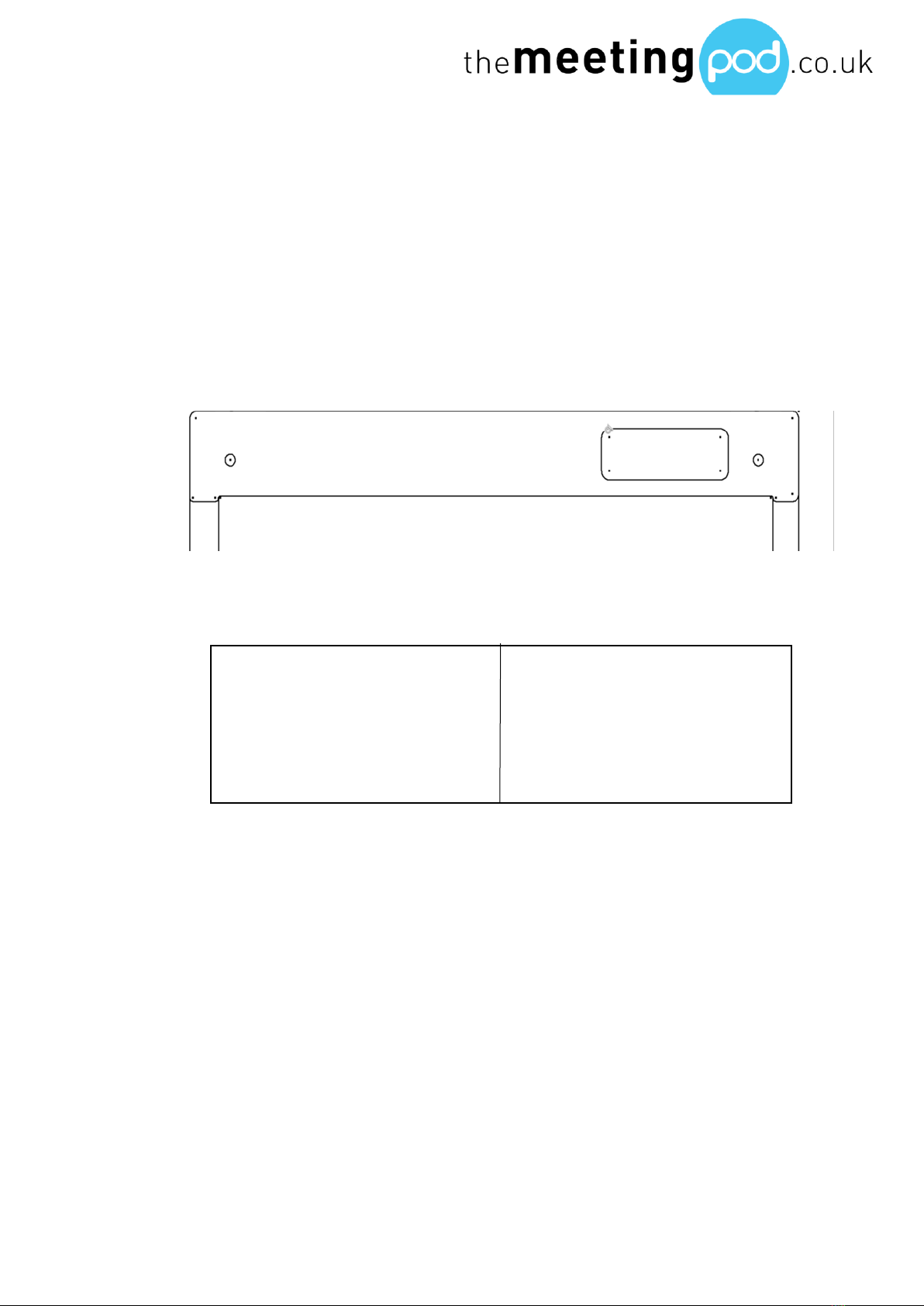
-Four pre-drilled bolting hold will be visible in composite seat base
Bolting holes
Installation Guide
9 Meeting Pod Installation Guide sales@themeetingpod.co.uk
-Use 4 x m6 penny washers and 4 x m6 self-tapping screws to fix down-
using a M10 spanner
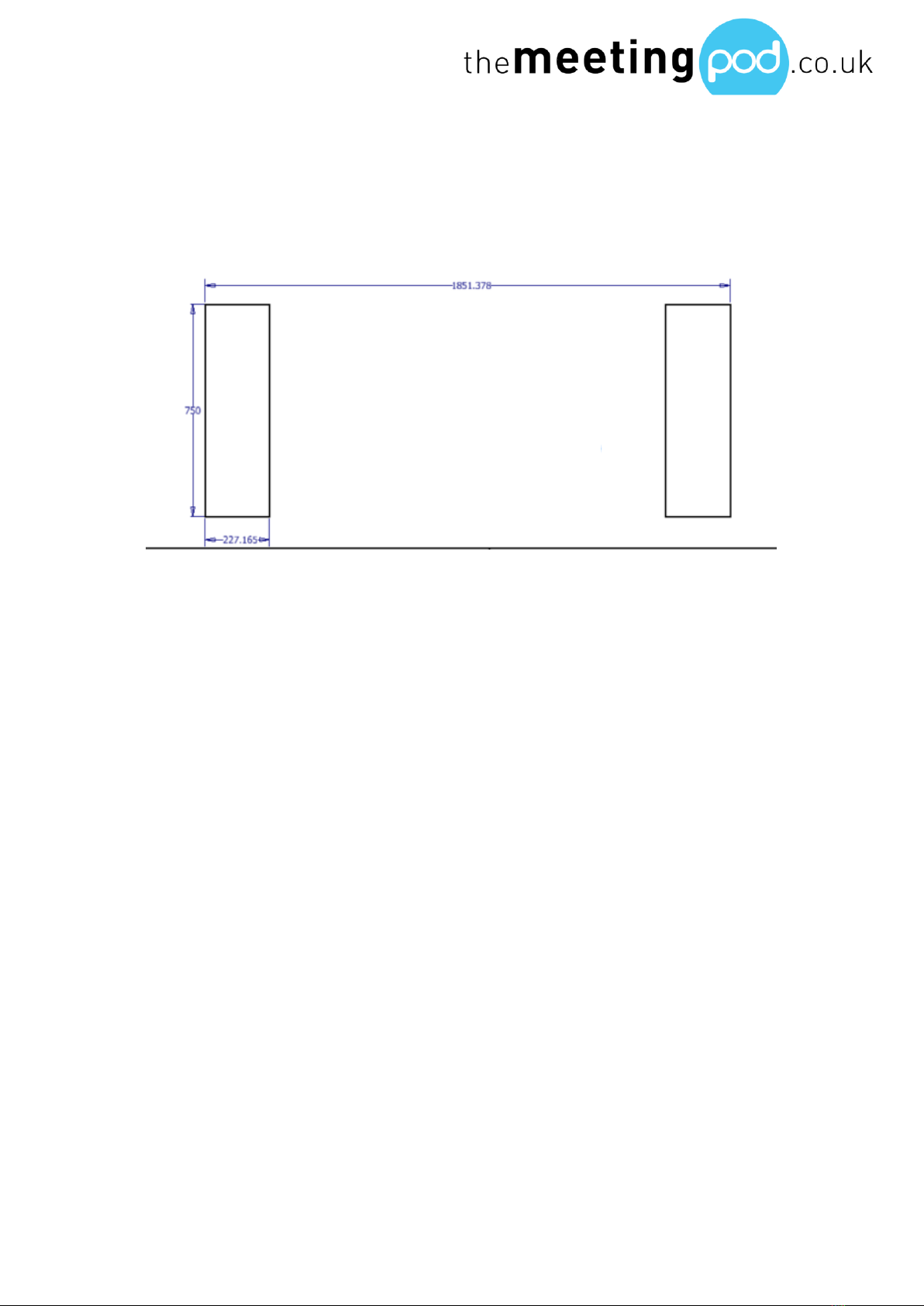
-Once one side is fixed, align the other segments accordingly. See
below for dimensions
-Repeat fixing down process once segments in correct location
-Use a straight edge to ensure there is no twist within the front facing
planes of the pods. If a straight edge is not avaiable, please use the
method of measuing to the nearest wall
Final process
-Once all the steps have been followed, place cushions back down by
pushing back of cushions into the pod acoustic foam, and align
accordingly to front and back of composite seat base
Pod bases

Installation Guide
10 Meeting Pod Installation Guide sales@themeetingpod.co.uk
Pod Accessories
Rear Glass Enclosure
Tools required: 2 x 6mm glass wings, 10 x glass adapters and glass adapter
key (supplied)
-Locate rear left and right pods. Pods can be located via labelling
system on the front face of the pod (fix each wing onto pods before
they are assembled)
-Wipe clean bolting surface of glass and pod
-Ensure floor is clean and free of debris
-Bolt glass wings onto pod using glass adapters. Start from the bottom
and work way up (this removes any discrepancies in alignment that
may occur)

Installation Guide
11 Meeting Pod Installation Guide sales@themeetingpod.co.uk
-Tighten all glass adapter hand tight. Final tension is gained using glass
adapter key. Work 1 to 5 (1 being bottom, 5 being top), tighten glass
adapters clockwise
-Repeat process on other wing
-Once complete, bring pods together leaving 60mm face to face at
the top
-Push pods carefully into desired location. Leave 30mm gap to insert
back panel
-Wipe clean glass faces
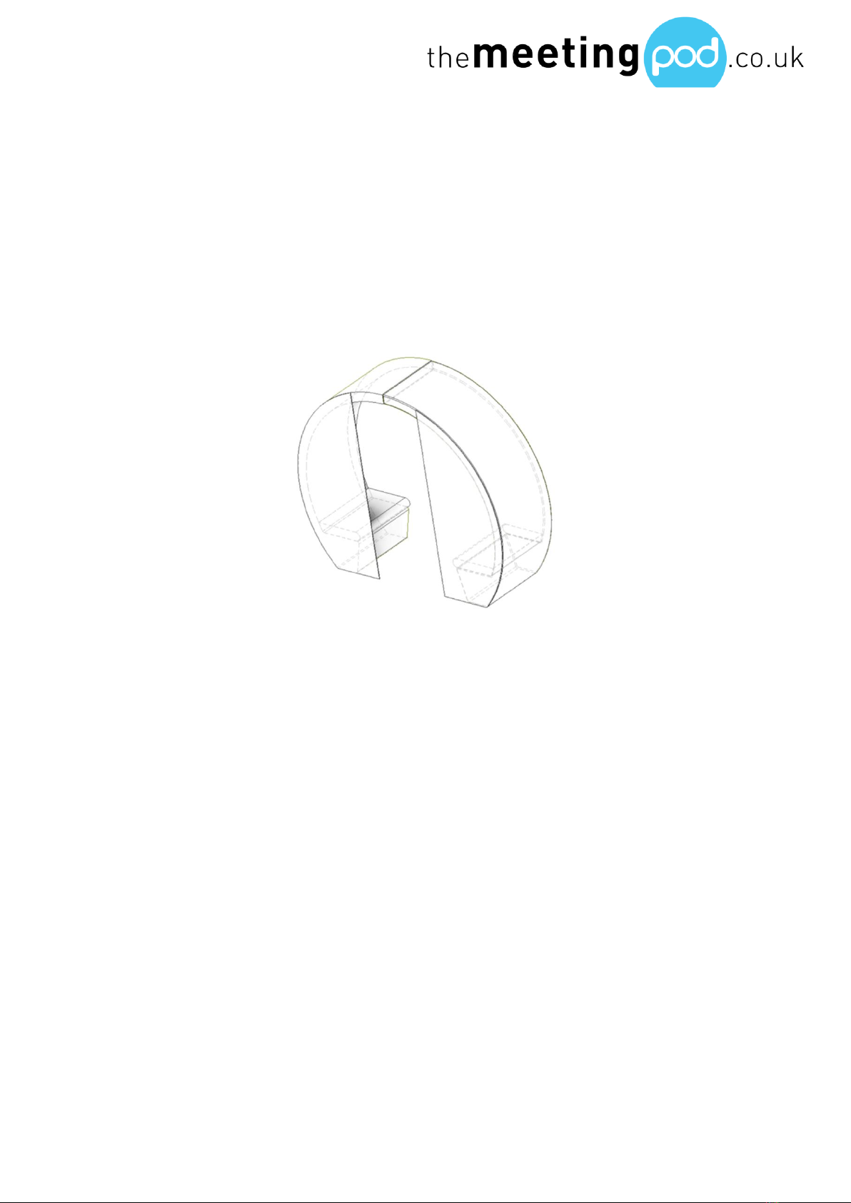
Central Core Back Panel
Tools required: 4 x m6 washers, 2 x m6 bolts, 2 x m6 nuts, 2 x 10mm socket
spanners and spray adhesive
-Slide central core Y section over the edge of the glass wing
-Pull opposite pod into place
-Ensure both wings are positioned correctly in Y section grove
-Carefully pull down top 300mm of acoustic foam

Installation Guide
12 Meeting Pod Installation Guide sales@themeetingpod.co.uk
-Place 2 x 25mm x 6mm bolts over 2 x m6 penny washers. Place bolts
through the opening holes on the right hand pod (when facing the
product)
-Place 2 x m6 penny washers and 2 x m6 onto the male end of the bolts.
Hand tighten
-Ensure top join of pods are in correct alignment
-Left hand nut will require open ended m10 spanner
-Right hand bolt will require a m10 spanner with extension bar to gain
access to turn tight.
-Tighten bolts in clockwise motion
Front Glass Enclosure
Tools required: 2 x 10mm glass wings, 2 x 8mm glass doors, 10 x glass adapters,
4 x glass to glass hinges, 2 x glass handles, 2 x silicone stopper, glass adapter
key (supplied), m6 Alan key, pozi screwdriver and packers
-Locate front left and right pods, putting them near the desired end
location. Pods can be located via labelling system on the front face of
the pod
-Wipe clean bolting surface of glass and pod
-Ensure floor is clean and free of debris
Installation Guide
13 Meeting Pod Installation Guide sales@themeetingpod.co.uk
-Bolt glass wings onto pod using glass adapters. Start from the bottom
and work way up (this removes any discrepancies in alignment that
may occur)
-Tighten all glass adapter hand tight. Final tension is gained using glass
adapter key. Work 1 to 5 (1 being bottom, 5 being top), tighten glass
adapters clockwise
-Repeat process on other wing
-Ensure all glass adapters are tightened correctly
-Make sure all pod alignment is correct in both planes and eliminate
any twists within the pods
Hanging glass doors
-Collect 4 x glass to glass hinges
-Remove the machine screws using the Alan key supplied within the
pack
-Collect right hand glass door- ensure glass door is correct. Magnet can
be found on the left-hand side on the outwards face. The door will
automatically pull into the hidden reverse magnet within the pod
-Pack the door until hinge holes on glass door and wing are horizontally
level

Installation Guide
14 Meeting Pod Installation Guide sales@themeetingpod.co.uk
-Place hinge through machines holes in glass
-Ensure hinge fixing holes are facing inwards towards the pod, leaving a
seamless machine hinges finish on the exterior of the glass. The hinge
leaf containing two knuckles should always be on the glazed wing
-Ensure rubber leafs and gaskets are in place before tightening
machine screws
-Tighten all four screws clockwise using the m6 Alan key
-Ensure glass is packed up and taking weight directly into the ground
before fitting second hinge
-Repeat process on other door
-Remove all packers
-Ensure doors hang freely
-To eliminate damage push left-hand door shut into concealed
magnet, making sure the door stays shut
-Repeat process on right-hand door

Installation Guide
15 Meeting Pod Installation Guide sales@themeetingpod.co.uk
-Ensure all hinge machine screws are tightened correctly
-Ensure glass alignment is parallel between the door and the glass wing.
6mm gap
-Ensure glass to door joining alignment is parallel. 4mm gap is necessary
for acoustics
(to achieve parallel lines, move pods either in or out to shut or open
glass gaps)
-Ensure top arcs of pod segments are in true radius
Fitting Handles
-Unpack 2 x glass handles
-Loosen grub screw on the top and bottom of the handle using Alan
key supplied. Ensure not to drop or lose screws when dismantling
-Remove machine screw from back side of the front handle
-Place screws through the located holes on the glass, found on the
inner leading edges
-Place handles through holes
-Join back handle onto front hand on the other side of the glass
-Ensure grub screw is in correct position, then retighten screw with Alan
key
-Test pull the handle to chick rigidity in fixing
-Repeat process on other handle

Installation Guide
16 Meeting Pod Installation Guide sales@themeetingpod.co.uk
Silicone stoppers
-Peel off silicone stoppers from backing film
-Stick on the inside of the glass door, behind the centre of the magnet
Additional Pod Segments
Tools required: 8 x m6 washers per additional segment, 4 x m6 bolts per
additional segment, 4 x m6 nuts per additional segment and 2 x 10mm socket
spanners

Installation Guide
17 Meeting Pod Installation Guide sales@themeetingpod.co.uk
-Remove top 300mm acoustic foam to gain access to fixing holes
-Place m6 bolt and m6 washer through the hole into the other pod
segment
-Place m6 washer and m6 nut on the male side of the bolt
-Hand tighten
-Ensure alignment is correct. If yes, then tighten further using spanners
-Collect 3 x m6 nuts and 3 x m6 washers, place through the locating
holes under the seat
-Match remaining 3 x m6 nuts and 3 x m6 washers through the other
pod segment and hand tighten
-Tighten further using spanners
-Repeat process on opposite side and for any additional segments
Installation Guide
18 Meeting Pod Installation Guide sales@themeetingpod.co.uk
Pod Electrics: Lighting & Power
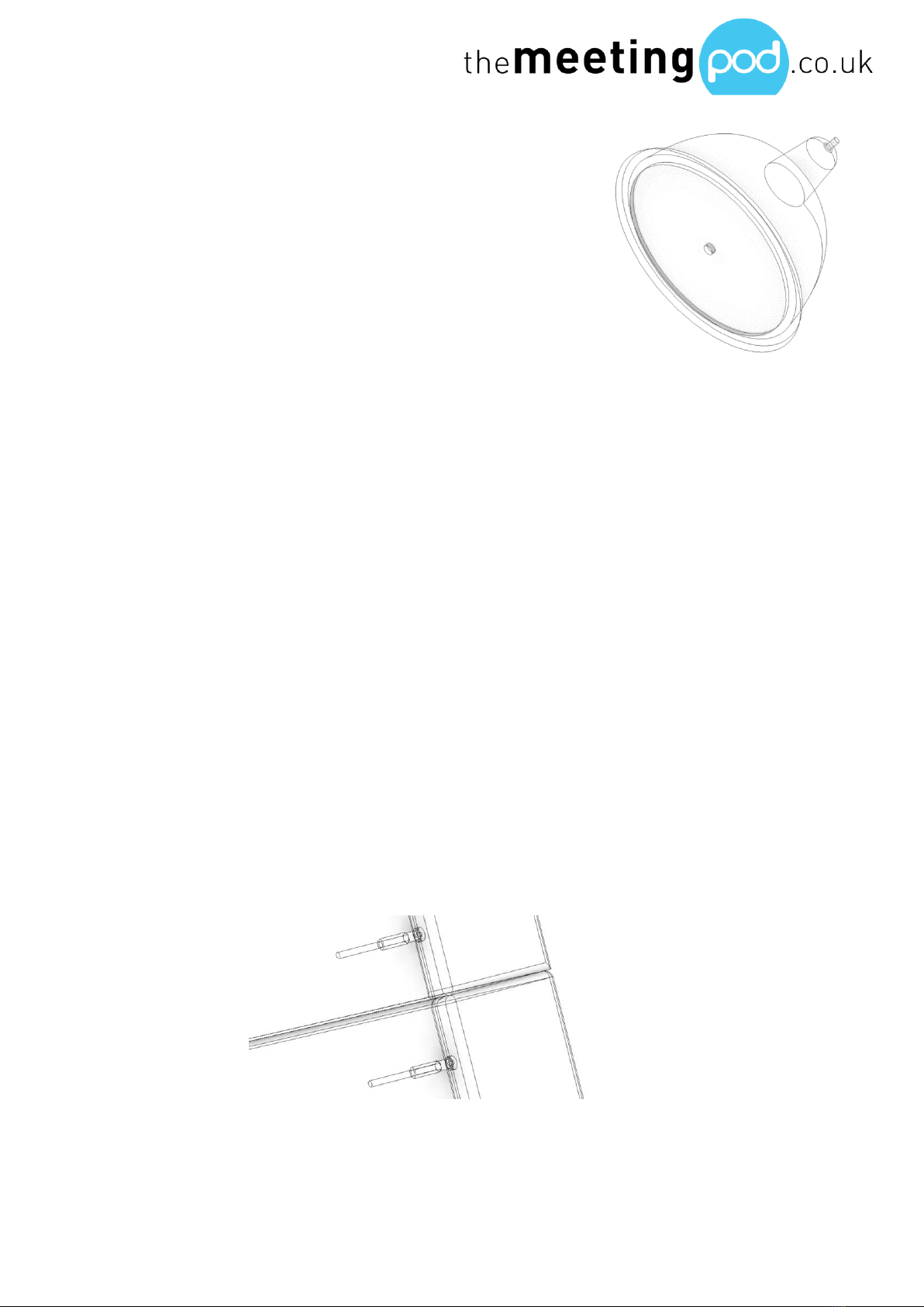
Lighting
Note: Light fitting can only be completed once the
pods have been secured together
Fitting
-Locate lighting track from packaging
-De-tangle any lines from the track
-Place snap hooks on D-rings found at back of pod
-Ensure light bulbs are facing down
-Pull tight cable tracks until tension buckles reach D-rings at the
entrance of the pod
-Tighten tension buckles in a clockwise motion until track is taught.
Removing any sag from line
-Ensure bulbs are vertically level
Pod with Back Panel
-Ensure snap hooks are connected securely to D-rings at entrance of
the pod
-Check the tension is correct
-De-tangle any lines from the track
-Place male connectors into the two female connection ports located
at the top of the back panel
-Ensure connection is pushed in correctly

Installation Guide
19 Meeting Pod Installation Guide sales@themeetingpod.co.uk
Open ring pod
-Ensure snap hooks are connected securely to D-rings at entrance of
the pod
-Check the tension is correct
-De-tangle any lines from the track
-Place male connectors into the two female connection ports located
at the top of the composite rib
-Ensure connection is pushed in correctly

Installation Guide
20 Meeting Pod Installation Guide sales@themeetingpod.co.uk
Warranty: Pod & Accessories
Pod components
Warranty length
Covered when installed correctly
Shell
12 months
-All pod shells should be wiped
clean with no smears
-All bolts present in joining holes
-Pods screwed down correctly
-Accurate silicone beading
applied
Acoustic foam
12 months
-Ensure all edges are secured
-Test pull each foam edge
Cushions
12 months
-Ensure Velcro has been
applied to pod seat base and
underside of cushion correctly
-Place cushions directly onto
Velcro
-Test pull cushions to assure no
lifting
Back panel central
core
12 months
-Ensure back panel is bolted
into wings correctly
-Ensure back panel is level
-Table is secure and correctly
fixed
Lighting
12 months
-Confirm lighting track is taut
-Bulbs are tightened and caps
clicked into place
-Electric modules fitted in back
panel correctly
Table: 2 person
12 months
-Table fitted correctly to back
panel
This manual suits for next models
3
Table of contents


