Extron electronics Retractor 2 Series User manual

1
This guide provides basic instructions for an experienced technician to install the Extron
Cable Retraction System with Speed Control for CableCubby®Enclosures. The retraction
system can be installed in Cable Cubby, Cable Cubby Series/2, AVEdge™, and Cable
Cubby TouchLink®Touchpanel enclosures, as well as the TMK 120 R Table Mount Kit.
Additional instructions are available in the user guides for the enclosures and TMK 120 R at
www.extron.com.
NOTE: For information on safety guidelines, regulatory compliances, EMI/EMF compatibility, accessibility, and related topics,
see the Extron Safety and Regulatory Compliance Guide on the Extron website.
Planning
The Retractor modules can be mounted in horizontal, vertical, or angular orientation depending on under‑table clearance and
accessibility.
• Horizontal mounting is recommended to provide maximum legroom and to protect the modules against accidental damage.
• Vertical mounting is used where insufficient under‑table space exists for horizontal mounting or under‑table access is limited.
• Angular mounting is used where insufficient under‑table space exists for horizontal mounting and tabletop to floor clearance
prevents vertical mounting. The enclosure has additional mounting holes that enable mounting at a fixed angle between
vertical and horizontal.
NOTES:
• For horizontal mounting, a mounting bracket kit is required.
• Filler modules are required to occupy unused Retractor space.
• For Retractor Series/2 DC modules, refer to the website for laptop compatibility. Always use a power supply
recommended by the laptop manufacturer.
Mounting kits, ller modules, and accessories are available at www.extron.com.
For new installations, to determine the best location for the enclosure, keep in mind the under‑table space required for the
retraction system. Refer to the enclosure installation guide to mount the enclosure.
NOTE: When connectivity brackets, AAP plates, and AAP modules are relocated or removed to provide space for the
retraction system, associated hardware can require reconfiguration or replacement. Before starting an installation,
determine if additional hardware is needed.
Required Tools and Additional Accessories
Horizontal Mounting
Bracket (Optional)
Tape Measure
Hex Nut Driver
(10 mm) Phillips Screw Driver
Zip Ties
Marker Pen
Tweeker
Filler Module
(Optional)
Determine Under-Table Clearances
Follow the Retractor installation instructions provided in your enclosure user guide to determine a suitable mounting location.
The diagrams on the following page show the space required for a retraction system installation in a compatible enclosure.
NOTES:
• To prevent objects from impeding cable retraction, ensure the exposed cable clears nearby obstructions.
• Excess cabling can cause clearance issues. Use zip ties to secure under‑table cabling to prevent accidental contact or
entanglement with users.
Retractor Series/2 • Installation Guide
Retractor Series/2 • Planning and Tools
IMPORTANT:
Go to www.extron.com for the complete
user guide, installation instructions, and
specifications before connecting the
product to the power source.

2
Retractor Series/2 • Installation Guide (Continued)
Mounting Orientation
The Retractor modules are mounted from below the enclosure.
Horizontal Mounting: Be certain the Horizontal Mounting Bracket can be fastened under the table or on a table support without
bending the pulley system or forcing it from perpendicular with the enclosure (see Prepare the Enclosure on the next page.
Vertical Mounting: Ensure the retraction system hangs freely without touching the oor and is not obstructed by anything under
the table. The standard system requires about 24inches (61cm). An XL system requires about 30inches (76.2 cm) from the top
of the furniture to clear the oor.
Angular Mounting: Angular mounting is necessary where the enclosure size and installation location makes retractor installation
too long for vertical mounting and there is not adequate under‑table clearance for horizontal mounting. An additional mounting
hole allows the system to install at an angle providing extra oor clearance (see diagrams below, right).
Retractor Series/2 • Under-table Clearances
Retractor Series/2 XL
29.4"
(747 mm)
26.9"
(683 mm)
30
24.2"
(615 mm)
20.5"
(521 mm)
9.0"
(229 mm)
11.5"
(292 mm)
NOTE: Shown with optional Cable Cubby enclosure.
Retractor Series/2
30
8.0"
(203 mm)
23.3"
(592 mm)
9.0"
(229 mm)
18.2"
(462 mm)
14.5"
(368 mm)
21.7"
(551 mm)
Horizontal Mounting Vertical Mounting Angular Mounting
NOTE: Retractor Series/2 and Retractor Series/2 XL
illustrations are shown with optional
Cable Cubby 1202 enclosure.
Pigtails
*6’ (1.8 m) Std.
4’ (1.2 m) XL and USB 3.0 Std.
*To make connections to devices under the table, standard Retractor modules have 6 feet (1.8m) of pigtail from the exit of
the cable retainer, while XL and USB 3.0 standard Retractors have 4 feet (1.2m) (see the illustration above). Depending on the
Retractor mounting and the location of the devices, you may require patch cables to extend the reach of the pigtail.
If you need to connect to devices further than the pigtails allow, contact your Extron representative or go to www.extron.com for
a full line of patch cables.

3
Product Category
Prepare the Enclosure
Ensure the retraction system has adequate under‑table clearance for
installation and that proper legroom is provided to avoid accidental
contact with the system. You should have the required accessories for
mounting the retraction system and to congure the enclosure.
DANGER:
• Disconnect the power from the Cable Cubby enclosure
before beginning a Retractor system installation.
• Débranchez l’alimentation du boîtier CableCubby avant de
commencer l’installation d’un système de Rétracteur.
Horizontal
Bracket
Top View
USBCHARGER
Retractor Series/2 • Prepare the Enclosure and Retractors
Prepare the Retractors
The Retractor modules are delivered ready to mount vertically. No further modications are required. Conrm proper tension
alignment using the cable tension adjustment instructions on the product label. If the connector (or stop collar) does not seat fully
against the cable release assembly, conrm proper tension adjustment using the instructions on the product label.
To Mount a Retractor Horizontally or at an Angle:
Remove two enclosure screws
(one on each side) from this position
for horizontal and angular mounting.
Install two enclosure screws
(one on each side) in the
angular mounting location.
Cable Release Assembly
For angular mounting, move the
cable release assembly upw
ard until
the angular mounting hole is visible.
Go to step 3.
-or-
For horizontal mounting,
proceed to the Installation section.
1
2
3
Rotate the cable release
assembly to the horizontal
position for installation.
4
Angular Mounting
Hole
Connector (or Stop Collar)
To Mount a Retractor in an Angled Position for Increased Under-Table Clearance:
Remove two enclosure screws
(one on each side) from this position
for horizontal and angular mounting.
Install two enclosure screws
(one on each side) in the
angular mounting location.
Cable Release Assembly
For angular mounting, move the
cable release assembly upward until
the angular mounting hole is visible.
Go to step 3.
-or-
For horizontal mounting,
proceed to the Installation section.
1
2
3
Rotate the cable release
assembly to the horizontal
position for installation.
4
Angular Mounting
Hole
Connector (or Stop Collar)

4
Retractor Series/2 • Installation Guide (Continued)
Retractor Series/2 • Installation and Horizontal Bracket Mounting
Installation
The enclosure must be installed and properly congured
before beginning the retraction system installation.
1. Follow the enclosure installation instructions for
new installations, or prepare an existing enclosure
installation to mount the Retractor modules.
2. Follow the Retractor mounting instructions in
the enclosure installation guide (see the example
installation at right).
3. Connect retraction system cables and other
AAPcables (if installed).
4. For horizontal mounting, proceed to the Horizontal
Bracket Mounting section below.
5. For vertical and angular mounting, proceed to Locking
Screws on page5 for final installation details.
NOTE:
Example installation shown with
optional Cable Cubby 700 enclosure.
Horizontal Bracket Mounting
For horizontal mounting, use the horizontal mounting bracket to x the
Retractor module under the table. Slotted holes allow for tolerance in
placing the bracket.
To ensure accuracy follow these procedures:
1. With the Retractor modules installed in the enclosure, attach the
horizontal mounting bracket to the end caps using the provided
hardware.
TIP: Hand tighten the nut enough to keep the bracket from
easily moving. The bolt and nut are removed later.
2. Raise the Retractors with attached bracket to the desired mounting
location.
NOTE: Be certain the system is perpendicular to the enclosure
(see the top view diagram on the previous page) to
prevent binding of the pulley system.
3. Ensure the bracket is flush with the surface and trace a line around the
bracket perimeter.
4. Lower the assembly and remove the horizontal bracket from the
Retractor modules. Trace around
bracket perimeter.
Horizontal Bracket
Mounting Holes
Slotted Hole
End Caps

5
Product Category
Retractor Series/2 • Locking Screw and Initial Adjustments
5. Position the bracket inside the lines drawn in step3and
fasten with the supplied screws.
ATTENTION:
• Ensure the supplied screws do not pierce through
the top of the table. Use appropriate screws based
on the table material and thickness.
• Assurez vous que les vis fournies ne transpercent
pas la surface de la table. Utilisez des vis plus
appropriées en fonction du matériau de la table et
de son épaisseur.
6. Raise the Retractor system up into the installed bracket, run
the bolt through the bracket and end caps, and secure with
the supplied nut.
7. See the “Locking Screw” section for final installation details.
Mounted in
Horizontal Position
Locking Screws
A locking screw on each Retractor and ller module prevents
them from rotating on the enclosure mounting bolt during
operation. Tighten each locking screw to prevent movement
of the Retractor (see the illustration at right).
NOTE: Do not overtighten. The locking screw only
needs to be snug.
Initial Adjustments
Once the Retractor is installed, verify proper Retractor
operation and perform necessary adjustments.
CAUTION:
• Do not operate a Retractor until it is installed.
• Retraction should be a slow, controlled motion.
• Keep hands away from moving parts.
ATTENTION :
• Ne vous servez pas d’un rétracteur avant qu’il soit
installé.
• La rétraction doit être un mouvement lent et
contrôlé.
• N’approchez pas vos mains des parties en
mouvement.
Tighten locking
screw (1 each).
ATTENTION:
• Do not overtighten the horizontal mounting nut. It only needs to be snug. Overtightening could deform the end
caps and cause misalignment of the system resulting in poor cable extension and retraction.
• Ne serrez pas trop l’écrou de montage horizontal. Il faut seulement qu’il soit bien ajusté. Le fait de trop serrer
pourrait déformer les capuchons aux extrémités et provoquer un mauvais alignement du système, ce qui limiterait
l’extension et la rétraction des câbles.

6
Retractor Series/2 • Installation Guide (Continued)
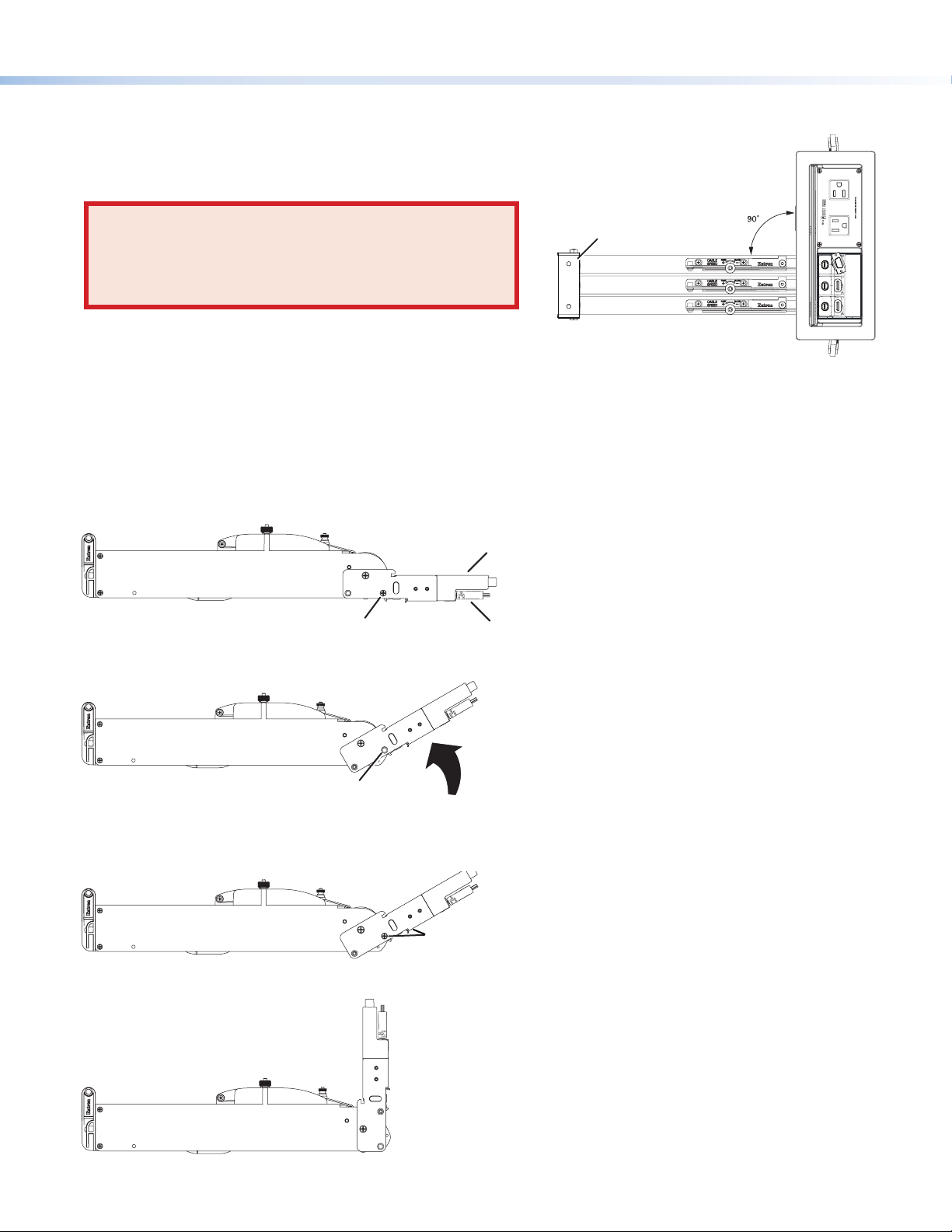
Retractor Series/2 • Speed Control Adjustment and Operation
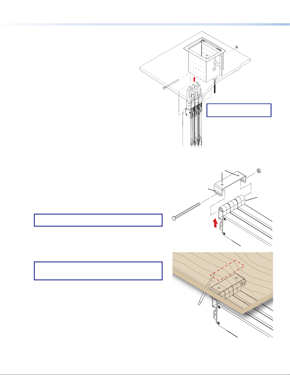
Confirm Proper Cable Extension
To extend the cable, hold it by the connector and pull the cable from the Retractor to its full length.
Confirm Proper Cable Retraction
To retract a cable, see the diagram at right.
CAUTION: Use one hand to control
the cable as it retracts. A cable
allowed to retract too quickly and
without control can cause possible
injury to the user or damage the
furniture surface,
Cable Cubby, and nearby items.
ATTENTION : Utilisez une main
pour contrôler le câble lorsqu’il se
rétracte. Un câble qu’on laisse se
rétracter trop rapidement et qu’on
ne contrôle pas peut provoquer
d’éventuelles blessures ou
endommager la surface du meuble,
du CableCubby, ou des objets à
proximité.
• If the cable does not retract to suit
your application, see “Speed Control
Adjustment.”
• When the stop collar (or connector, if the
cable does not have a stop collar) is seated
against the cable release assembly, release
the button and cable.
• If the stop collar (or connector) does not seat fully against the cable release assembly, confirm proper tension adjustment
using the instructions on the product label.
Speed Control Adjustment
The Retractor Series/2 is delivered with the speed control adjusted for
nominal operation in all mounting orientations (vertical, horizontal, and
angular). However, speed control adjustment may be required in your
application.
NOTES:
• Ensure the speed control knob remains fully seated, with the teeth of the knob engaged throughout adjustments.
• Retraction speed is affected by the installation orientation (vertical, horizontal, or angular). Always test speed
adjustments with the Retractor in its installed position.
The speed control adjusts the cable retraction speed. Turn the speed control a quarter‑turn clockwise (the control “clicks” as it
turns) to slow the cable retraction. Test the speed after each quarter‑turn until the desired speed is reached. If the retraction is too
slow after the nal quarter‑turn, turn the knob counterclockwise one “click” at a time, retesting after each “click”, until the desired
speed is reached.
If the cable retraction is too fast, adjust the speed control clockwise in the same manner.
Retractor Operation
When initial adjustments are complete, the Retractor is ready for operation. To connect a cable, grip the connector and pull
enough cable from the Retractor to connect it to the device. There is no need to press the cable release button. When you stop
pulling the cable, the Retractor xes the length automatically.
To retract the cable, press and hold the cable release button until the cable is seated on the cable release assembly.
Hold the cable taut
by the connector.
Press and hold the
cable release button.
Slowly allow the cable
to be pulled back until
the stop collar (or connector)
is seated against the cable
release assembly.
Release the cable
and button.
1
2
3
4
Speed
Control

7
Product Category
Retractor Series/2 • Laptop Power
Laptop Power
The Retractor Series/2 DC, Retractor Series/2 XL DC, Retractor Series/2 Lenovo DC, Retractor Series/2 XL Lenovo DC, Retractor
Series/2 USB‑C Power, and Retractor Series/2 XL USB‑C Power modules provide a connection for a device on the tabletop to a
compatible power supply (not supplied) under the furniture. Installation of the Retractor is identical to other Retractor modules.
The cable has a female connector under the furniture (2) for connection to a power supply(1), and male connector on the
topside (3) of the table for connection to a compatible device.
ATTENTION:
• Use only the power supply recommended by the manufacturer of the laptop.
• Utilisez uniquement la source d’alimentation recommandée par le frabricant de l’ordinateur portable.
• See the Cable Retraction System DC Power Compatibility Guide at www.extron.com for devices compatible with the
Retractor modules.
• Consultez le guide Cable Retraction System DC Power Compatibility Guide sur www.extron.com pour vérifier les
appareils compatibles avec les modules Retractor.
DC Power
Connector
Laptop
(not supplied)
Power Supply
(not supplied)
Under-table
Connector
1
2
3
Under‑furniture space for the Retractor and power for the OEM power supply must be available. The power supply module must
be safely located and supply leads dressed to avoid entanglements and accidental contact.
The power supply (see 1in the illustration above) must be compatible with both the device power requirements and the female
connector (2) on the under‑table end of the Retractor cable. The male DC power connector (3) must be compatible with the
power connection of the device.
Labels
The Retractor Series/2 DC and Retractor Series/2 XL DC include labels (Dell, HP, and
blank‑printable) for the topside connector to identify the laptop it is compatible with. Afx the
appropriate label as shown at right.

The Retractor Series/2 USB-C - HDMI and Retractor Series/2 XL USB-C - HDMI include
labels (Video, Display icon, and blank‑printable) for the connector to identify cable as
supporting AV signals only from DisplayPort Alternate Mode (DP Alt Mode) devices (see the
illustration at right).
Quick Installation Checklist
Planning (page 1)
Ensure there is adequate space available in the enclosure.
Obtain optional mounting brackets and accessories necessary for the application.
If reconfiguration of the Cable Cubby enclosure is required, obtain the necessary connectivity brackets, AAPs, and mounting
frames.
If necessary, obtain filler modules to occupy unused Retractor space in the enclosure.
Gather tools needed for installation (page 1).
Determine Under-table Clearances (pages 1-2)
Follow the Retractor system instructions provided with the enclosure user guide.
Choose the mounting orientation (page 2):
• Horizontal mounting — Ensure space is available for the horizontal bracket location.
• Vertical mounting — Ensure the retraction system hangs freely.
• Angular mounting — Use angular mounting where vertical mounting is desired but the
tabletop to floor distance is less than 30 inches.
Prepare the Cable Cubby Enclosure (page 3)
Disconnect all power to the Cable Cubby.
Configure the connectivity brackets, AAPs, and mounting frames.
Prepare the Retractors (page 3)
To mount the Retractor modules horizontally or at an angle, remove the two Retractor enclosure screws.
Install the Retractors (pages 4-5)
Connect all retraction system cables and other cables.
For horizontal mounting, determine the bracket mounting location and install the bracket (page 4).
Tighten the locking screws (page 5).
Initial Adjustments (page 5-6)
Verify proper operation of each Retractor and adjust tension or speed control as necessary
Retractor Operation (page 6)
After initial adjustments, the Retractor system is ready for normal operation.
Laptop Power (page 7)
If a Retractor Series/2 DC, Retractor Series/2 Lenovo DC, or Retractor Series/2 USB‑C Power is installed, connect your laptop
power supply.
68-2485-50 Rev. D
04 19
For information on safety guidelines, regulatory compliances, EMI/EMF compatibility, accessibility, and related topics, see the
Extron Safety and Regulatory Compliance Guide on the Extron website.
© 2016‑2019 Extron Electronics — All rights reserved. www.extron.com
All trademarks mentioned are the property of their respective owners.
Worldwide Headquarters: Extron USA West, 1025 E. Ball Road, Anaheim, CA 92805, 800.633.9876
Table of contents
Popular Office Equipment manuals by other brands

Konig + Neurath
Konig + Neurath ACTA.PLUS operating instructions

3-form
3-form SimpleSpec 200.62-ILTUO installation manual

Herman Miller
Herman Miller Canvas Office Landscape Support Panel Installation and Disassembly for Recycling Instructions

Jason.L
Jason.L Quadro Loop Legs 6P 120 Degree Workstation with... Assembly instructions

Framery
Framery One manual

J.Burrows
J.Burrows Stilford JBSHBB18WW Assembly instructions