12345
Matrix 2019
www.ais-inc.comwww.ais-inc.com 6
P-MXINSTRUCT01 Rev 07.29.2020
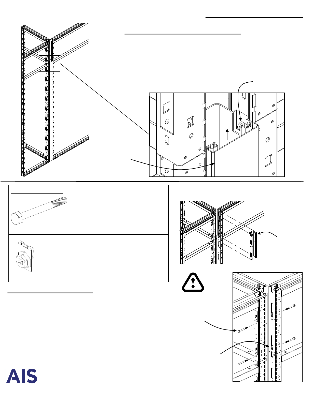
Stack-On Connectors
#10-32 Hex Nut
Remove Base Connector Vertical Cover:
1. Remove and save #10-32 Hex Nuts and
Bolts at top of Connector (2 places)
2. Slide Vertical Cover up approximately ¾”
to release it from the bottom tabs.
Up
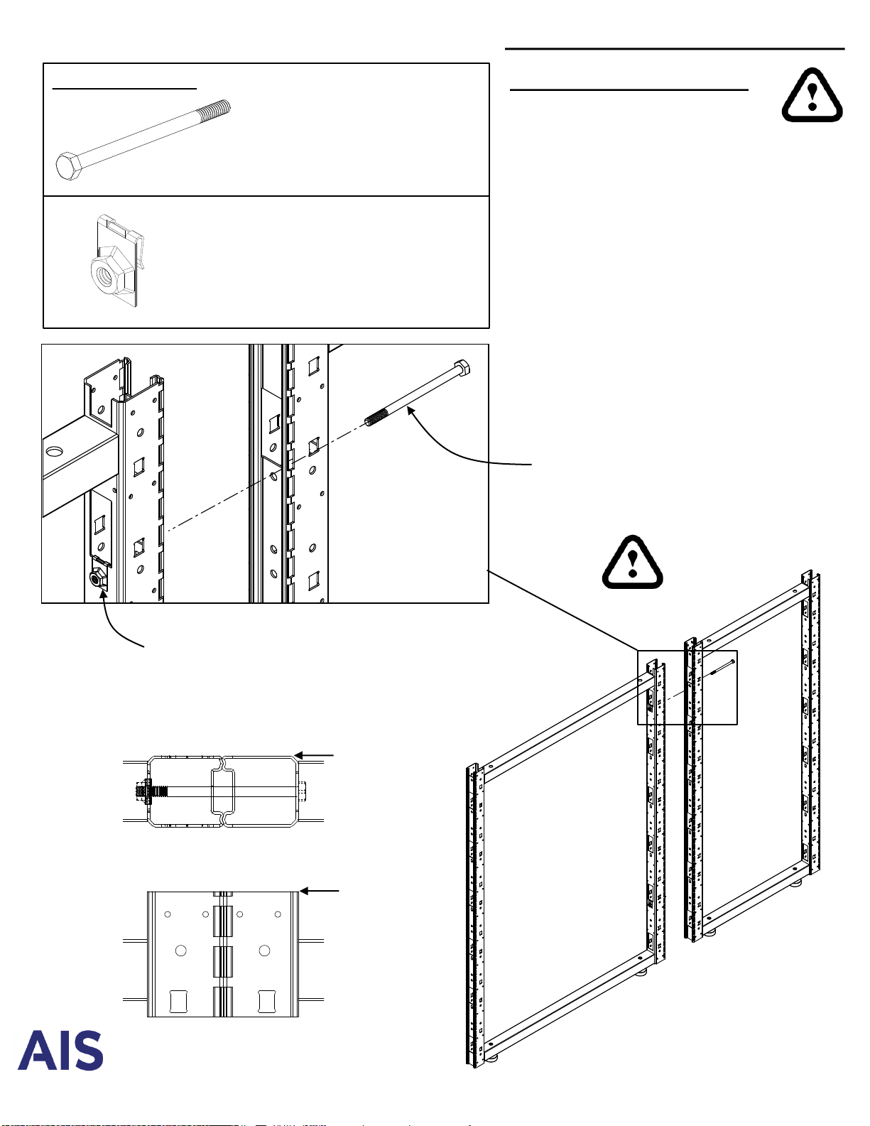
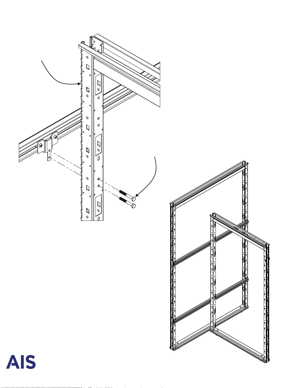
Required hardware: ¼-20 x 2 ¼” Hex Bolt
#RP-M2BOLT1
Use 7/16” magnetic hex drive
2-way Connection = 4 bolts
3-way Connection = 6 bolts
4-way Connection = 8 bolts
¼-20 Tinnerman Nut
#RS-HNC33892
(Factory installed, on one side of
frame. Installers may be required to
remove from frames if connecting to
2-way, 3-way or 4-way connector)
Stack-On
Connector
¼-20 Tinnerman Nut
May have moved during shipping.
To re-center, briefly insert
#2 philips screw driver through
connector hole into the
tinnerman nut.
¼-20 x 2 ¼” Hex Bolt
First bolt must be installed at
top of frame to ensure proper
vertical alignment
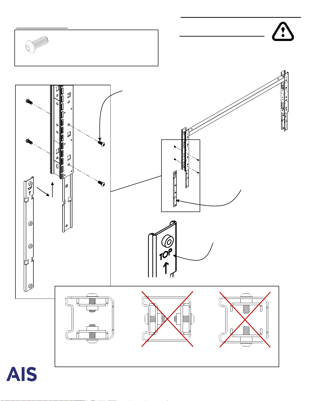
IMPORTANT INSTRUCTIONS:
•Place first bolt at top of frame, below
first electrical chase hole. This hole is
round and will align frames vertically. All
other bolt locations are slots.
•Thread all bolts loosely, making sure
bolts are properly threaded to prevent
cross-stripping. Tighten top bolt first,
then tighten all remaining bolts to
approx. 100 inch lbs torque, or using a
12 volt drill on medium torque.
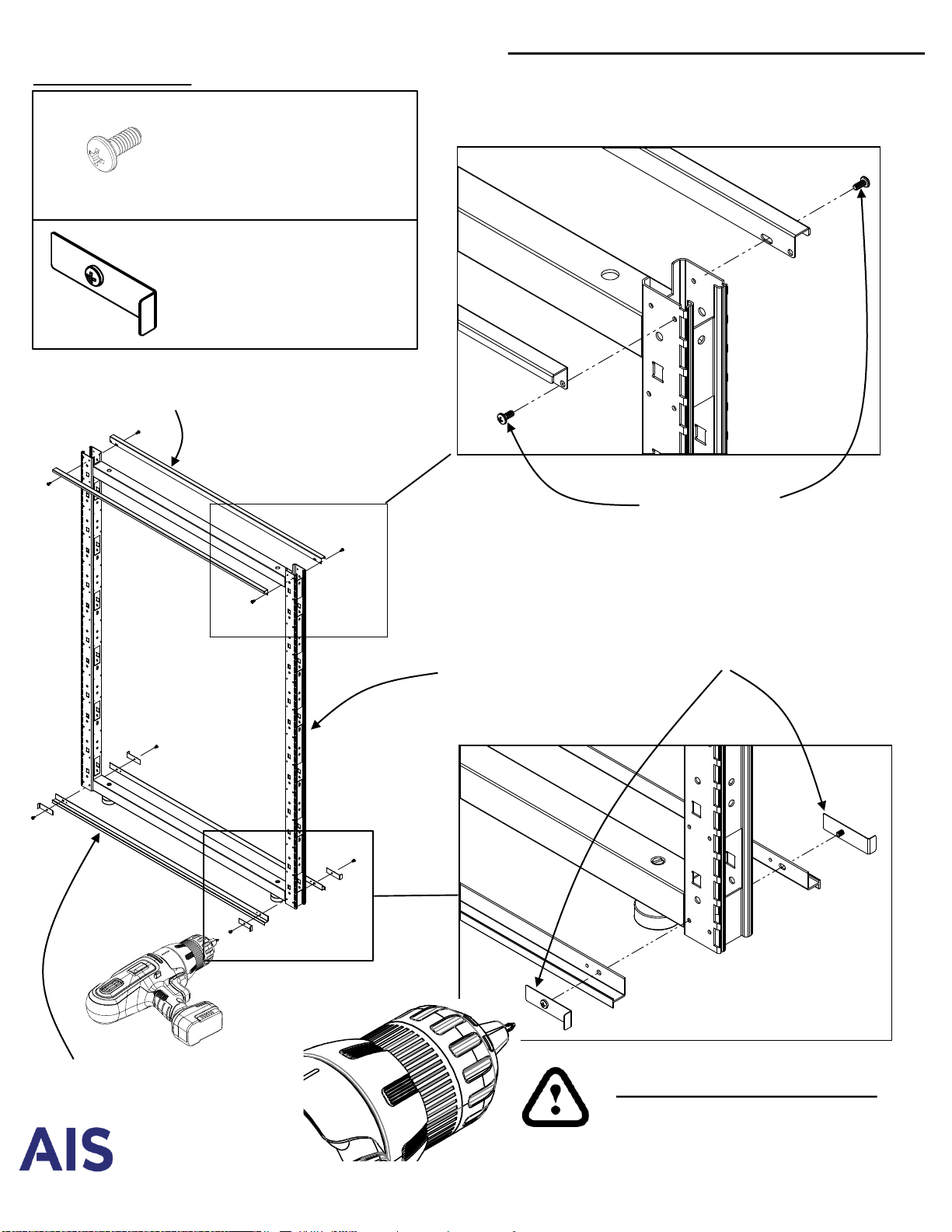
Lift off
Vertical Cover