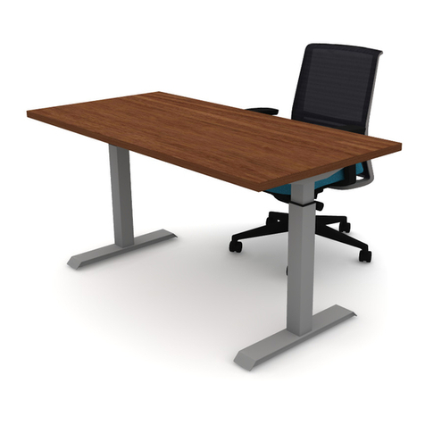
Kimball National Naviyd User manual

1
Proper product installation, in accordance with these instructions, is the responsibility of the installing agent.
If you have any questions concerning these instructions, please call Kimball Customer Care.
Part 3111703,-
Assembly Instructions
IMPORTANT SAFETY INFORMATION
WARNING, Risk of Electric Shock, Fire, and Injury. Read the
ENTIRE IMPORTANT SAFETY INFORMATION section at the
beginning of this document including all text under subheadings therein
before set up or use of this product to confirm appropriate critical
components and accessories are being used with the furnishing.
DANGER – To reduce the risk of electric shock:
1. Always unplug this furnishing from the electrical outlet before cleaning.
WARNING – To reduce the risk of burns, fire, electric shock, or injury to persons:
1. Unplug from outlet before putting on or taking off parts.
2. Close supervision is necessary when this furnishing is used by, or near children, invalids, or disabled per-
sons.
3. Use this furnishing only for its intended use as described in these instructions. Do not use attachments not
recommended by the manufacturer.
4. Never operate this furnishing if it has a damaged cord or plug, if it is not working properly, if it has been
dropped or damaged, or dropped into water. Return the furnishing to a service center for examination and re-
pair.
5. Keep the cord away from heated surfaces.
6. Never operate the furnishing with the air openings blocked. Keep the air openings free of lint, hair, and the
like.
7. Never drop or insert any object into any opening.
8. Do not use outdoors.
9. Do not operate where aerosol (spray) products are being used or where oxygen is being administered.
10. To disconnect, turn all controls to the off position, then remove plug from outlet.
11. For chairs and similar furnishings with movable parts such as foot supports the following statement:
“WARNING: Risk of Injury – Keep children away from extended foot support (or other similar parts).”
12. For grounded products the following statement:
“WARNING: Risk of Electric Shock – Connect this furnishing to a properly grounded outlet only. See
Grounding Instructions.”
13. For loading always put heavier items at the bottom and not near the top in order to help prevent the possi-
bility of the furnishing tipping over.
14. If a surface is not intended to support video monitors such as televisions or
computer monitors, one of the following statements:
‘Warning: Risk of Injury to Persons – do not place video equipment such as
televisions or computer monitors on ________” where the blank is filled in to
identify the particular surface
“Warning: Risk of Injury to Persons – do not use this furnishing to support video equipment such as televi-
sions or computer monitors.”
15. Each surface intended to support a load shall have a corresponding statement in the use instructions speci-
fying the maximum intended load for that surface in pounds and (kilograms). Refer to 31.3.1.
Max Load per base: 265lbs
XSEDE®
Naviyd™ Height Adjust


2
Proper product installation, in accordance with these instructions, is the responsibility of the installing agent.
If you have any questions concerning these instructions, please call Kimball Customer Care.
Part 3111703,-
Assembly Instructions
For a grounded furnishing, the instructions shall include those instructions in (a) – (c) applicable to the fur-
nishing. For a double insulated furnishing the instructions shall include (d).
GROUNDING INSTRUCTIONS
a) For a grounded, cord-connected product rated max 15 amperes and intended for use on a nominal 120-volt
supply circuit :
This product is for use on a nominal 120-volt circuit and has a grounding plug that looks like the plug illus-
trated in sketch A. Make sure that the product is connected to an outlet having the same configuration as the
plug. No adapter should be used with this product.
b) For all other grounded, cord-connected products:
This product is for use on a circuit having a nominal rating more than 120 volts (or “This product is rated
more than 15 amperes and is for use on a circuit having a nominal rating of 120 volts”) and is factory-
equipped with specific electric plug to permit connection to a proper electric circuit. Make sure that the prod-
uct is connected to an outlet having the same configuration as the plug. No adapter should be used with this
product.
c) For a permanently connected product:
GROUNDING INSTRUCTIONS
This product must be connected to a grounded metal, permanent wiring system, or an equipment-grounding
conductor must be run with the circuit conductors and connected to the equipment-grounding terminal or lead
on the product.
d) For a double-insulated, cord-connected product:
SERVICING OF DOUBLE-INSULATED PRODUCTS
In a double-insulated product, two systems of insulation are provided instead of grounding. No grounding
means is provided on a double-insulated product, nor is a means for grounding to be added to the product.
Servicing a double-insulated product requires extreme care and knowledge of the system, and is to be done
only by qualified service personnel. Replacement parts for a double-insulated product must be identical to the
parts they replace. A double-insulated product is marked with the words “DOUBLE INSULATION” or
“DOUBLE INSULATED.” The symbol (square within a square) is also able to be marked on the product.
IMPORTANT GROUNDING INFORMATION
SKETCH A
XSEDE®
Naviyd™ Height Adjust
3
Proper product installation, in accordance with these instructions, is the responsibility of the installing agent.
If you have any questions concerning these instructions, please call Kimball Customer Care.
Part 3111703,-
Assembly Instructions
1. Assemble Feet to two Columns using supplied Socket
Round 5/16-18 X 5/8” screws. Tighten Screws Firmly. See
Figure B.
IMPORTANT: Make sure the correct screws are used. Using
longer screws may destroy the internal parts of the column.
2. Loosen the set screw and set the Crossbar length based on
top size as seen in Figure C below. Attach the crossbars on
the long side of the bases using supplied Socket Flat Head
5/16-18 X 1” screws. See Figure C.
IMPORTANT: Make sure the correct screws are used. Using
longer screws may destroy the internal parts of the column.
Figure A
Assembled Product
Xsede Height Adjust 3 Column
T-Leg
Hardware
4—Round Head Socket 5/16-18 X 5/8”
12—Flathead Socket 5/16-18 X 1”
4– Flathead Phillips 1/4-20 X 5/8”
12-Clear Bumpers 1/2” Round X 1/8”
4-Clear Bumpers 1/2” Square X 1/4”
8-Panhead Phillips #8X3/4” Wood Screw
12-Flathead Phillips #10-2 3/8” Wood Screw
4– Panhead Phillips #8 X 5/8” Wood Screws
4-Cable ties.
1— Power Supply Bracket
Installation Figure B– Attach Feet
Figure C– Attach Cossbar
Do not use middle hole of cross bar
Tools Required
3/16” Hex Drive
#2 Phillips Drive
Drill
Sidebar
Column
Foot
Crossbar
48”
54”
60”
66”
72”
Top
XSEDE®
Naviyd™ Height Adjust

4
Proper product installation, in accordance with these instructions, is the responsibility of the installing agent.
If you have any questions concerning these instructions, please call Kimball Customer Care.
Part 3111703,-
Assembly Instructions
3. Attach sidebars to crossbars with Phillips Flathead 1/4-20” X
5/8” screws. See Figure D
4. Place adhesive bumpers on the crossbars. The bumpers
should be places as close to the fixing screws as possible.
The bumpers come in two thicknesses. The thicker, square
ones are used on the inner tube. See Figure E.
5. Slide Power Supply Bracket over crossbar as shown in Fig-
ure F.
6. Attach Base to a worksurface using supplied Panhead
#8X3/4” and flathead #10X2-3/8” wood screws. Route hand-
set Cable between the Crossbar and the surface prior to
attaching. The shorter screws goes in the sidebars. The
longer screws go into the crossbars. See Figure G.
IMPORTANT: supplied screws are designed to work with a
worksurface with a minimum thickness of 3/4”
Figure D– Sidebar Attachment
Xsede Height Adjust 3 Column
T-Leg
Installation Continued
Figure E– Spacing Bumpers
Figure G– Worksurface Attachment
Figure F– Power Supply Support
4 1/2”
4 1/2”
23”D E EP -(1 1/16”)
29”D E EP -(4 1/16”)
23”D E EP -(1 1/16”)
29”D E EP -(4 1/16”)
#8 X 5/8”Panhead Woodsc rews
#10 x 2 1/4”Flathead
XSEDE®
Naviyd™ Height Adjust

5
Proper product installation, in accordance with these instructions, is the responsibility of the installing agent.
If you have any questions concerning these instructions, please call Kimball Customer Care.
Part 3111703,-
Assembly Instructions
6. Attach the handset to front edge of the worksurface using in-
cluded #8 X 5/8” Panhead Wood Screws. Connect the
cables and power supply. Use Cable Ties to secure
wiring to base. Ensure no cables are hanging down.
See Figure H.
Figure H– Electrical Assembly
Xsede Height Adjust 3 Column
T-Leg
Installation Continued
Warning leaflet and user manual should be
Warning Leaflet Electric User Manual
XSEDE®
Naviyd™ Height Adjust

1
Proper product installation, in accordance with these instructions, is the responsibility of the installing
agent. If you have any questions concerning these instructions, please call Kimball Customer Care.
Part 3111703,-
Assembly Instructions
1. Assemble Feet to two Columns using supplied Socket
Round 5/16-18 X 5/8” screws. Tighten Screws Firmly. See
Figure B.
IMPORTANT: Make sure the correct screws are used. Using
longer screws may destroy the internal parts of the column.
2. Loosen the set screw and set the Crossbar length based on
top size as seen in Figure C below. Attach the crossbars on
the long side of the bases using supplied Socket Flat Head
5/16-18 X 1” screws. See Figure C.
IMPORTANT: Make sure the correct screws are used. Using
longer screws may destroy the internal parts of the column.
Figure A
Assembled Product
Height Adjust 3 Column T-Leg
Hardware
4—Round Head Socket 5/16-18 X 5/8”
12—Flathead Socket 5/16-18 X 1”
4– Flathead Phillips 1/4-20 X 5/8”
12-Clear Bumpers 1/2” Round X 1/8”
4-Clear Bumpers 1/2” Square X 1/4”
8-Panhead Phillips #8X3/4” Wood Screw
12-Flathead Phillips #10-2 3/8” Wood Screw
4– Panhead Phillips #8 X 5/8” Wood Screws
4-Cable ties.
1— Power Supply Bracket
Installation Figure B– Attach Feet
Figure C– Attach Cossbar
Do not use middle hole of cross bar
Tools Required
3/16” Hex Drive
#2 Phillips Drive
Drill
Sidebar
Column
Foot
Crossbar
48”
54”
60”
66”
72”
Top
XSEDE®
Naviyd™ Height Adjust

2
Proper product installation, in accordance with these instructions, is the responsibility of the installing
agent. If you have any questions concerning these instructions, please call Kimball Customer Care.
Part 3111703,-
Assembly Instructions
3. Attach sidebars to crossbars with Phillips Flathead 1/4-20” X
5/8” screws. See Figure D
4. Place adhesive bumpers on the crossbars. The bumpers
should be places as close to the fixing screws as possible.
The bumpers come in two thicknesses. The thicker, square
ones are used on the inner tube. See Figure E.
5. Slide Power Supply Bracket over crossbar as shown in Fig-
ure F.
6. Attach Base to a worksurface using supplied Panhead
#8X3/4” and flathead #10X2-3/8” wood screws. Route hand-
set Cable between the Crossbar and the surface prior to
attaching. The shorter screws goes in the sidebars. The
longer screws go into the crossbars. See Figure G.
IMPORTANT: supplied screws are designed to work with a
worksurface with a minimum thickness of 3/4”
Figure D– Sidebar Attachment
+HLJKW$GMXVW&ROXPQ7/HJ
Installation Continued
Figure E– Spacing Bumpers
Figure G– Worksurface Attachment
Figure F– Power Supply Support
4 1/2”
4 1/2”
23”D E EP -(1 1/16”)
29”D E EP -(4 1/16”)
23”D E EP -(1 1/16”)
29”D E EP -(4 1/16”)
#8 X 5/8”Panhead Woodsc rews
#10 x 2 1/4”Flathead
XSEDE®
Naviyd™ Height Adjust

3
Proper product installation, in accordance with these instructions, is the responsibility of the installing
agent. If you have any questions concerning these instructions, please call Kimball Customer Care.
Part 3111703,-
Assembly Instructions
Figure H– Electrical Assembly
+HLJKW$GMXVW&ROXPQ7/HJ
Installation Continued
6.Attach the handset to front edge of the worksurface using
in-cluded #8 X 5/8” Panhead Wood Screws. Connect the
cables and power supply. Use Cable Ties to secure
wiring to base. Ensure no cables are hanging down.
See Figure H.
Warning leaflet and user manual should be
Warning Leaflet Electric User Manual
XSEDE®
Naviyd™ Height Adjust
This manual suits for next models
1
Table of contents
Other Kimball Office Equipment manuals
Popular Office Equipment manuals by other brands

Regency
Regency MABP27 instructions

aidapt
aidapt VM964 Usage and maintenance instructions

Ahrend
Ahrend Silence Call 2.0 manual

Herman Miller
Herman Miller Canvas Office Landscape In-Line Beam... Installation and Disassembly for Recycling Instructions

Fellowes
Fellowes SafeCut Atom user guide

TREMAIN
TREMAIN Link installation manual