Megasat WSTA-DP250PMS User manual

24
Campingman Twin Auto Skew
(WSTA-DP250PMS)
User´s Manual

25
1 Introduction
Specification………………….…………………………………………………….5
Antenna System Overview…………………………………………………….6
Direct Broadcast Satellite Overview………………………….…………..7
System Components……………………………………………………………8
2 Installation
Unpac ing the Unit………………………………..…………………….......9
Preparing for the installation……………………………………………….10
Selecting the location………….……………………………………….……...11
Equipment and cable installation…………..…………………………….12
Setting the LNB S ew Angle(Manual S ew version only)………..13
3 Operation
Receiving Satellite TV Signals…………….……………………………….14
Turning the System On/Off…………..………………..…………………..15
Changing Channels………………………….…………………...…..………..15
Watching TV…………………………………………………………..……..…..15
Switching between Satellites………………………………………………..15
Operating the IDU……………………………………….…………………..16
4 Troubleshooting
Simple Chec ……………………………………………..………………….19
Causes and Remedies……………………………….……..……………….20
Appendix A How to set the s ew angle……………………………..…..…….21
Appendix B Satellite Coverage Map………………………………..………..…26
Appendix C Antenna Drawing..….…………………….………………………..28
Appendix D Adhesive Instruction.…………………….………………………..30
T
able of contents
able of contentsable of contents
able of contents

26
Notes, Cautions, and Warnings
Caution – Improper handling by unqualified personnel can cause
serious
damage to this equipment. Unqualified personnel who tamper with
this
equipment may be held liable for any resultant damage to the
equipment.
Install under DRY condition ONLY! Do not install this system in the
rain,
or under any wet conditions. Moisture may affect electronics and
void warranty!
Warning – Need 2 people to install the antenna onto the roof. Do
not try to install the antenna by yourself.
Note – Before you begin, carefully read each of the procedures in
this manual. If you have not performed similar operations on
comparable equipment, do not attempt to perform these procedures.
Specification
SpecificationSpecification
Specification
Antenna Type Parabola
Frequency Band Ku Band
Radome Dimension 700x400mm
Antenna Weight 12kg
Antenna Gain 33dBi
Minimum EIRP 49dBW
Polarization V/H or RHCP/LHCP
Type of Stabilization 2-Axis Step Motor
Elevation Range 15°to 62°
Azimuth Range Unlimited
Tracking Rate 50°/sec
Temperate Range -20°to 70°
Power 12~24VDC
LNB Twin Auto Skew
Table 1-1 Specification

27
WSTA-DP250PMS satellite antenna system is the innovative and a technologically
advanced satellite Stationary system. WSTA-DP250PMS has a unique combination of state-
of-the art components with the most sophisticated satellite acquisition and tracking programs
to provide the following features:
■Fast satellite acquisition
■Compatible with any Satellite Receiver
■Compatible with all Direct Broadcast Satellites (DBS)
■Built-in Digital Broadcast Receiver(DVB)
■Capable of High Definition receiving
■Automsatic Skew
■Twin output for 2 Receivers
I
ntroduction
ntroductionntroduction
ntroduction

28
Antenna System Overview
Antenna System OverviewAntenna System Overview
Antenna System Overview
A complete satellite TV system, illustrated in Figure 1-1, includes WSTA-DP250PMS
antenna connected to a IDU, a satellite TV receiver, and a television set.
Antenna
Satellite Receiver
1
Campingman
DP250PMS
Antenna Unit
IDU(In Door Unit)
Satellite Receiver
2
Vehicle Power
12V/24VDC
Figure 1
-
1
Syste Diagra
TV
T
V
or Power supply
230VAC/12VDC 5A
Antenna

29
Direct Bro
Direct BroDirect Bro
Direct Broadcast Satellite Overview
adcast Satellite Overviewadcast Satellite Overview
adcast Satellite Overview
Direct Broadcast Service (DBS) satellites broadcast audio, video and data information from
satellites located 22,000 miles in space. A receiving station, such as WSTA-DP250PMS
antenna, should include a dish and satellite receiver to receive the signals and process them
for use by the consumer audio and video equipment. The system requires a clear view of the
satellite to maximize the signal reception.
Objects such as tall lighthouse, bridges and big ship that block this view will cause a loss of
signal. The signal will be quickly restored once the antenna has a clear line of sight again.
Heavy rain, cloud, snow or ice may also interfere with the signal reception quality. If the
satellite signal is lost due to blockage or severe weather condition, services from the receiver
will be lost (picture will freeze frame and may disappear). When the satellite signal strength
is again high enough, then the receiver will resume providing desired programming services.
Figure 1
-
2 Satellite B
lockage
Free
!
Blocked
!
bad or no
signal !
good signal !

30
System Components
System ComponentsSystem Components
System Components
Antenna Unit
The antenna unit houses the antenna positioning
mechanism, LNB (low noise block), and control
elements within a radome. Weathertight
connectors join the power, signal, and control
cabling from the belowdecks units.
IDU(InDoor Unit)
The IDU is the system’s user interface, providing
access to the system and its functions through an
LCD and three buttons. The IDU also serves as
the vehicle’s junction box, allowing the system
to use vehicle power, and supply and receive
data to/from the antenna unit.
Figure 1
-
3 Syste Co ponents

31
This section offers a general explanation of how properly to install WSTA-DP250PMS
antenna. Installation of WSTA-DP250PMS antenna must be accomplished by or under the
supervision of an authorized dealer for the Limited Warranty to be valid and in force. The
steps in the installation and setup process are as follows:
Unpacking the unit
Unpacking the unitUnpacking the unit
Unpacking the unit
1. Open box and remove packing material.
The following items are included in the packaging of Free Way 1S antenna.
Item
Description
Quantity
1
Megasat WSTA-DP250PMS Antenna Unit 1 each
2
Megasat IDU(In Door Unit)
1 each
3
Power Cable(1.5m)
1 each
4
Coaxial Cable (10m)
1 each
5
Coaxial Cable (1m)
1 each
6
User Manual
1 set
7 Gluing set (Primer 50ml, Applicator,
Special adhesive 310ml) 1 set
Table 2-1 Parts included
2. Lift dome out of box vertically. Then lift unit out of box vertically. Do not turn box
and “roll” out, or turn upside down to remove.
Figure 2-1 Unpacking the unit
Lift Unit straight
up out of the
carton!
I
nstallation
nstallationnstallation
nstallation

32
Preparing for the instal
Preparing for the instalPreparing for the instal
Preparing for the installation
lationlation
lation
Install Tools and Materials
WSTA-DP250PMS antenna system is designed for simple installation and setup. However,
the following list of equipment or items should be available during installation of WSTA-
DP250PMS antenna.
■Electric drill and drill bits
■Socket wrench
■Silicon sealant
■Fastener suitable for specific application
1. Verification of the Vehicle’s Power Supply.
■Confirm that the vehicle’s power supply is 12VDC~24VDC or
Power supply with 230VAC to 12VDC 5A.
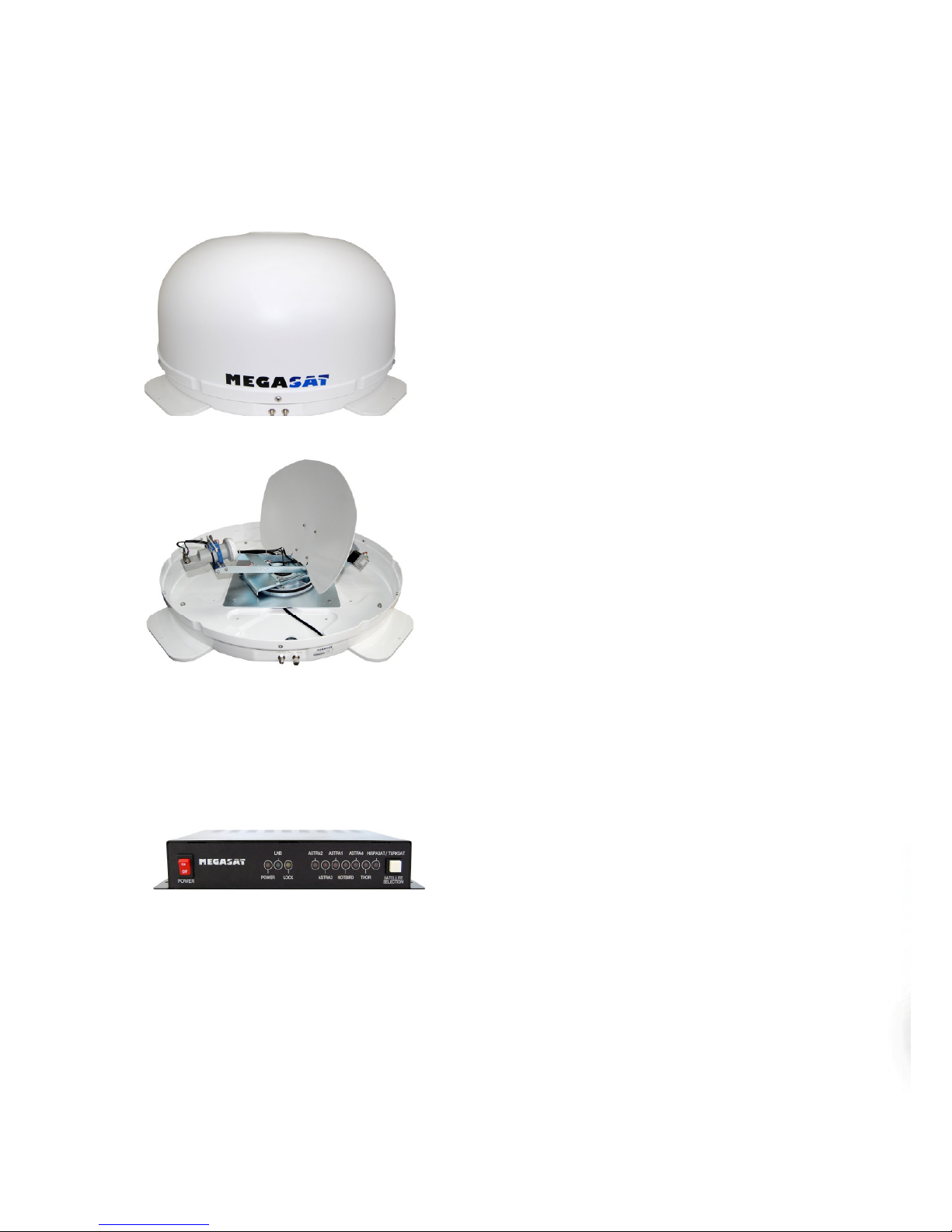
2. Verification of the Satellite Receiver and IDU’s attachment and the electricity supply
■Attach Satellite Receiver and IDU in the interior of the vehicle or the trunk.
■Connect the power of Satellite Receiver and IDU.
■Once the power of Satellite Receiver and IDU is verified, it confirms that both
Satellite Receiver and IDU are working normally.
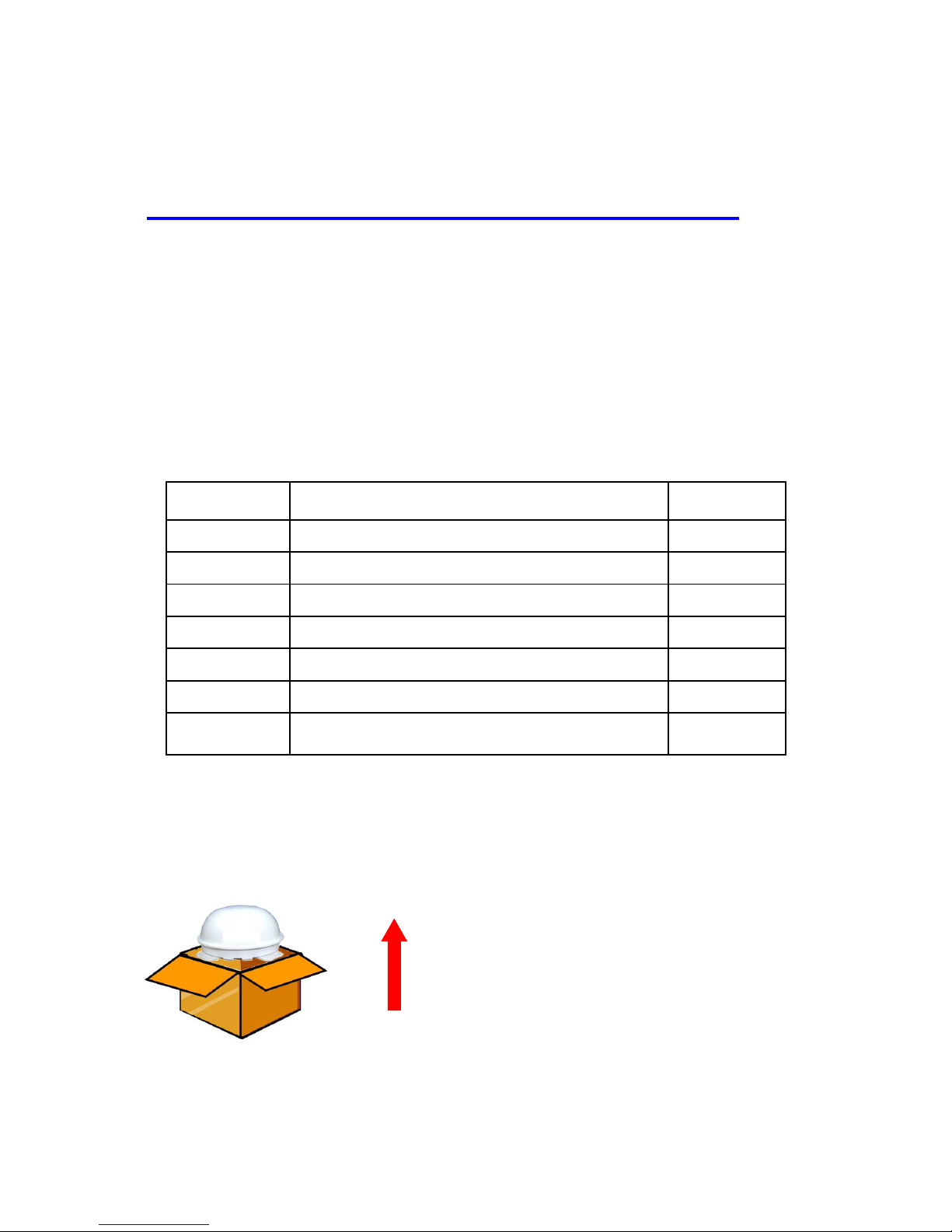
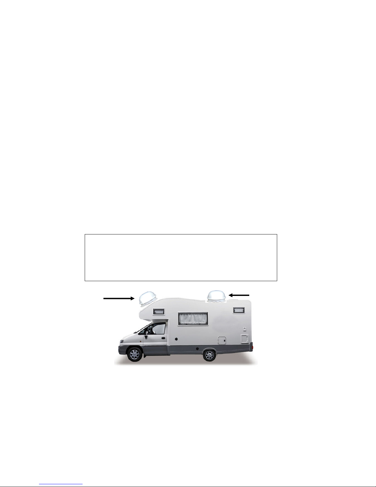
3. Procedure of the satellite’s attachment and installation.
■Attach the satellite on the flat surface area of the vehicle’s roof.
■Connect each end of the Coaxial antenna cable to the satellite’s terminal and the IDU.
■Connect the IDU and the Satellite Receiver box together through the coaxial cable.
■Make sure that the satellite is working normally, once the power is supplied.
Warning :
Things to consider when installing the antenna.
■Turn off the power when attaching or detaching the
antenna.
■Make sure that the attached satellite is fixed on the flat
surface.
■When attaching, ensure that all the products are adhered
properly.
■Ensure that all the cables are connected properly.

33
Best
Location
Poor
Location
Selecti
SelectiSelecti
Selecting the location
ng the locationng the location
ng the location
Determine the optimum mounting location for the antenna radome assembly. It should be
installed where :
1. The antenna has a clear line-of-sight view to as much of the sky as is practical. Choose
a location where masts or other structures do not block the satellite signal from the dish
as the vehicle turns.
2. The antenna is at least 5 feet away from other transmitting antennas (HF, VHF and
radar) that may generate signals that may interfere with WSTA-DP250PMS antenna.
The further away WSTA-DP250PMS antenna is from these other antennas, the less
impact their operation will have on it.
3. Direct radiation into the antenna from vehicles radar, especially high power
surveillance radar arrays, is minimized. The radome should be as far away from the
vehicles Radar as possible and should NOT be mounted on the same plane as the
vehicles Radar.
4. The antenna radome assembly should be rigidly mounted to the vehicle. If necessary,
reinforce the mounting area to assure that it does not flex due to the vehicle motion or
vibration.
If these conditions cannot be entirely satisfied, the site selection will inevitably be a “best”
compromise between the various considerations.
Figure 2-2 Selecting the location
Perform a through site inspection on the roof for the antenna
to
be mounted.
1. The antenna must have a clear view of the sky and the
horizon at all the directions to avoid blockage of the
satellite signal.
2. The antenna should be on the top of the vehicle.

34
Equipment and cable installati
Equipment and cable installatiEquipment and cable installati
Equipment and cable installation
onon
on
This offers a general explanation of how to install the IDU and satellite receiver properly to
the inside of vehicle connecting with coaxial cable.
1. The Coaxial cable is routed from the antenna to the IDU inside the vehicle.
2. After Once deciding where to place the IDU and satellite receiver, make sure that both
units are placed in a dry and protected area.
3. The IDU and satellite receiver should be placed away from any heat source and in an
area with proper ventilation.
4. Ensure that there are at least 3cm of space around both units for ventilation and
connection of cables. Do not stack the units on top of each other.
5. The following describes the basic wiring configurations for DP250PMS antenna.
■Connect the Coaxial cable to WSTA-DP250PMS antenna port on the back of IDU
■Connect one end of the supplied coaxial cable to the receiver port on the back
of the IDU
■Connect the other end of the coaxial cable to the satellite receiver
■The second receiver you can directly connect the coaxial cable from antenna to the
satellite receiver.
Setting the LNB skew angle
Setting the LNB skew angle Setting the LNB skew angle
Setting the LNB skew angle
Figure 2-3 Satellite signals

35
Attention –
The Model Megasat Campingman TAS
(Twin Auto Skew) work full automatically
Do not work on the auto skew system
(only for engineer).
Signals transmitted in vertical(red) and horizontal(blue) wave offset exactly 90º from each
other. Since linear satellite signals are oriented in a precise cross pattern, Free Way 1S
antenna’s receiving element, called an LNB (low-noise block) must be oriented in the same
way to optimize reception. This orientation adjustment is referred to as the LNB’s “skew
angle.” Figure 1-4 illustrates how skew determines the amount of signal the LNB collects.
The more signal, the better reception.
The correct skew setting varies depend on your geographic location, since the orient-tation of
your antenna to the satellite changes as you move. For complete details about adjusting the
LNB’s skew angle, see “Appendix A – How to Set the Skew Angle”
Figure
2
-
4 Best Skew
A
ngle
Bad
skew
Good
skew
Best
skew
: L B “signal collector”
: Satellite Signal
L B Center Line
(+) Direction
(
-
)
Direction

36
WSTA-DP250PMS antenna system is easy to use. Under normal conditions, operation of
WSTA-DP250PMS antenna requires no intervention from the user. Antenna unit
initialization , satellite acquisition and skew is completely automatic.
Receiving Satellite TV Signals
Receiving Satellite TV SignalsReceiving Satellite TV Signals
Receiving Satellite TV Signals
Television satellites are located in fixed positions above the Earth’s equator and beam TV
signals down to certain regions of the planet. To receive TV signals from a satellite, you must
be located within that satellite’s unique coverage area. To check it, see “Appendix B –
Satellite Coverage Map” In addition, since TV satellites are located above the equator,
WSTA-DP250PMS antenna must have a clear view of the sky to receive satellite TV signals.
Anything that stands between the antenna and the satellite can block the signal, resulting in
lost reception. Common causes of blockage include lighthouses, boat masts, trees, buildings,
and bridges. Heavy rain, ice, or snow might also temporarily interrupt satellite signals.
Turning the System On/Off
Turning the System On/OffTurning the System On/Off
Turning the System On/Off
Since power to WSTA-DP250PMS system is controlled by the IDU, you can turn the antenna
on or off by applying/removing operating power to the IDU.
Turning on the System
Follow the steps below to turn on your WSTA-DP250PMS System.
1. Make sure the antenna has a clear view of the sky.
2. Turn on your satellite TV receiver and TV.
3. Apply operating power to the IDU.
4. Wait one minute for system startup. The IDU will display the Tracking
Satellite screen after system testing is complete.
Turning off the System
Follow the steps below to turn off your WSTA-DP250PMS System.
1. Remove operating power from the IDU.
2. Turn off your satellite TV receiver and TV.
Changing Channels
Changing ChannelsChanging Channels
Changing Channels
If you have followed the installation instructions, your system should be set to the satellite of
your choice and the system should have downloaded the appropriate channel guides. When
WSTA-DP250PMS antenna system and satellite receiver is properly configured, it is easy to
change the channel using the remote control that normally comes with the receiver unit.
O
peration
perationperation
peration

37
Watching TV
Watching TVWatching TV
Watching TV
WSTA-DP250PMS antenna is designed to operate as efficiently and as reliably as possible
when the vehicle is moved and anchored. It is also the quickest satellite acquisition system
available among WSTA-DP250PMS antennas. If you have anchored the vehicle and the
antenna has completed to searching selected satellite, turn off IDU Power to avoid
unnecessary use of power. Because the LNB receives its power from the Satellite Receiver
through the IDU, the antenna will continue to receive the satellite TV signals.
Switching between Satellites
Switching between SatellitesSwitching between Satellites
Switching between Satellites
You can switch between satellites using the IDU by pressing Satellite select buttons. Follow
the steps below to switch to another satellite.
1.
Ensure that the LEDs turn on. If antenna is disconnected, all led will blink.
Figure 3-1 IDU LED
2. Press the Satellite select buttons to switch to another satellite.
3. The antenna shifts to track selected satellite. Wait for the Tracking Satellite
screen.
Operating the IDU
Operating the IDUOperating the IDU
Operating the IDU
Appearance
Figure 3-2 Appearance of IDU
ON
OFF
SATELLITE
SELECT
POWER
Power S/W
Satellite select button
SEARCH
S
LEEP
TRACKI G
ASTRA2
ASTRA2S
HOTBIRD
ASTRA1
SIRIUS
AB3
HISPSAT
SEARCH
S
LEEP
TRACKI G

38
Functions of LCD Display
Figure 3-3 Functions of LED
General Operation Order
Turn the power switch on.
.
Push the Satellite select buttons to choose
satellite.
Red LED turns on for searching the satellite.
ON
OFF
SATELLITE
SELECT
POWER
Power S/W
Satellite select button
SEARCH
S
LEEP
TRACKI G
ASTRA2
ASTRA2S
HOTBIRD
ASTRA1
SIRIUS
AB3
HISPSAT
It is searching
a satellite.
It is in sleep
mode.
It is tracking a
satellite.
ON
OFF
POWER
SEARCH
S
LEEP
TRACKI G
SATELLITE
SELECT
You can change
the satellite by
pushing this

39
It is tracking the target satellite.
If detacted satellite is choosen satellite, it goes
to auto_sleep mode.
In case of search failure
Turn the power switch on.
Push the Satellite select buttons to choose
satellite.
Red LED turns on for searching the
satellite.
If the antenna cannot find selected satellite, it
goes to sleep mode during about 2 minutes with
turning on 2-LED. And then the antenna will
search the satellite again.
SEARCH
S
LEEP
TRACKI G
SEARCH
S
LEEP
TRACKI G
SEARCH
S
LEEP
TRACKI G
ON
OFF
POWER
SEARCH
S
LEEP
TRACKI G
SATELLITE
SELECT

40
There are a number of common issues that can affect the signal quality or the operation of
WSTA-DP250PMS antenna system. The following sections address these issues and potential
solutions.
Simpl e chec ………………….….………………………………………….24
Causes and Remedies…..………………..………………………………….25
Simple check
Simple checkSimple check
Simple check
Can the antenna see the satellite?
The antenna requires an unobstructed view of the sky to receive satellite TV
signals. Common causes of blockage include trees, buildings, bridges, and
mountains.
Is there excessive dirt or moisture on the antenna dome?
Dirt buildup or moisture on the dome can reduce satellite reception. Clean the
exterior of the dome periodically.
Is it raining heavily?
Heavy rain or snow can weaken satellite TV signals. Reception should improve
once the inclement weather subsides.
Is everything turned on and connected properly?
Make sure your TV and receiver are both turned on and set up for the satellite
input. Finally, check any connecting cables to ensure none have come loose.
Causes and Remedies
Causes and RemediesCauses and Remedies
Causes and Remedies
Receiver Fault
Your satellite TV receiver might be set up incorrectly or defective. First check the
receiver’s configuration to ensure it is set up for the desired programming. In the
case of a faulty receiver, refer to your selected receiver’s user manual for service
and warranty information.
Satellite Coverage Issue
Television satellites are located in fixed positions above the Earth’s equator and
beam TV signals down to certain regions of the planet (not worldwide). To receive
TV signals from a satellite, you must be located within that satellite’s unique
coverage area. See “Appendix-B Satellite Coverage Map”
T
roubleshooting
roubleshootingroubleshooting
roubleshooting

41
Satellite Signal Blocked
The WSTA-DP250PMS Antenna needs a clear line of sight (LOS), view to the
satellite for uninterrupted reception. Objects such as tall lighthouse, bridges and
big ship that block this view will cause a loss of signal. The signal will be quickly
restored once the antenna has a clear line of sight again. Heavy rain, cloud, snow
or ice may also interfere with the signal reception quality. If the satellite signal is
lost due to blockage or severe weather condition, services from the receiver will be
lost (picture will freeze frame and may disappear). When the satellite signal
strength is again high enough, then the receiver will resume providing desired
programming services.
Satellite Frequency Data Changed
If some channels work, while one or more other channels do not, or if the antenna
cannot find the selected satellite, the satellite’s frequency data might have
changed.
Improper Wiring
If the system has been improperly wired, the antenna will not operate correctly.
Refer to the User Manual for complete system wiring information.
Loose Cable Connectors
We recommends periodically checking the antenna unit’s cable connections. A
loose cable connector can reduce signal quality or prevent automatic satellite
switching using the receiver’s remote control. Fasten the cable connector.
Appendix A
How to Set up the Skew Angle
Signals transmitted in vertical and horizontal wave
offset exactly 9 º from each other. Since linear satellite
signals are oriented in a precise cross pattern, Free Way
1S antenna’s receiving element, called an LNB (low-noise
block) must be oriented in the same way to optimize
reception. This orientation adjustment is referred to as
the LNB’s “skew angle.” The correct skew setting varies
depending on your geographic location, since the
orientation of your antenna to the satellite changes as you
move. This appendix provides how to set up the skew
angle.

42
European Position Grid
European Position GridEuropean Position Grid
European Position Grid
If you wish to determine the Skew Angle(LNB), use the position grid(Figure A-1
European Position Grid) and table(TableA-1 Regional Skew angle) on page
32.
Figure A-1 Europe Position Grid
If you wish to set the correct skew, see “TableA-1 Regional Skew angle”. The correct
skew setting varies depending on your geographic location, since the orientation of your
antenna to the satellite changes as you move.

43
Grid
um.
ASTRA2N
28.2°
°°
°E
ASTRA2S
28.2°
°°
°E
ASTRA1
19.2°
°°
°E
HOTBIRD
13.0°
°°
°E
SIRIUS
4.8°
°°
°E
THOR
0.8°
°°
°W
AB3
5.0°
°°
°W
HISPASAT
30°
°°
°W
1 13°13°10°7°3°1°-1°-11°
2 10°10°6°4°0°-3°-4°-14°
3 6°6°2°-1°-4°-7°-9°-18°
4 1°1°-3°-5°-9°-11°-12°-20°
5 -2°-2°-6°-9°-12°-14°-15°-22°
6 17°17°12°9°4°1°-1°-15°
7 13°13°8°5°0°-3°-6°-18°
8 8°8°2°-1°-6°-9°-11°-22°
9 2°2°-3°-7°-11°-14°-16°-25°
10 -3°-3°-8°-11°-15°-18°-20°-27°
11 21°21°16°12°6°2°-2°-19°
12 17°17°10°6°0°-4°-8°-23°
13 10°10°3°-2°-7°-11°-14°-28°
14 2°2°-4°-9°-15°-18°-21°-32°
15 -4°-4°-10°-14°-20°-23°-25°-34°
16 27°27°20°15°8°2°-2°-23°
17 21°21°14°8°0°-6°-10°-29°
18 12°12°4°-2°-10°-15°-18°-34°
19 3°3°-6°-11°-18°-23°-26°-38°
20 -5°-5°-13°-18°-25°-28°-31°-41°
21 33°33°25°19°9°3°-2°-29°
22 26°26°17°10°0°-7°-12°-35°
23 16°16°5°-2°-12°-18°-23°-41°
24 4°4°-7°-14°-23°-28°-32°-45°
25 -6°-6°-16°-23°-30°-34°-37°-48°
Table A-1 Regional Skew Angle
Table of contents