MEGASTEK XT-007 User manual

User Manual of Tracker
Version Number Modified by
Change Content Type
Date
V1.0 Moot create 2012.11.05
V1.1 Amy Modify 2014.05.19
GPS
Vehicle and Personal Multi-purpose Positioning
Tracker
_______________________________________
___
User Manual V1.1

User Manual of XT007
Contents
1. Products Overview...............................................................................................................- 1 -
2. For Your Safety....................................................................................................................- 2 -
3. Tracker Characteristics.........................................................................................................- 2 -
4. Getting Started .....................................................................................................................- 3 -
4.1 Hardware and Accessories .............................................................................................- 3 -
4.2 Function key and Interfaces...........................................................................................- 4 -
4.3 First Start........................................................................................................................- 6 -
5. Parameter Configuration......................................................................................................-8-
5.1 Set by SMS ....................................................................................................................- 8 -
5.2 Set by Software on PC...................................................................................................- 8 -
5.3 Set by GPRS...................................................................................................................- 9 -
6. Change Password.................................................................................................................- 9 -
7. Restore Default ....................................................................................................................- 9 -
8. Authorization number..........................................................................................................- 9 -
9. Tracking Via SMS..............................................................................................................- 10 -
9.1 Real Time Tracking............................................................................................- 10 -
9.2 Google Map Link...............................................................................................- 10 -
9.3 Tracking By Calling..................................................................................................... - 11 -
9.4 Tracking Regularly Via SMS....................................................................................... - 11 -
10. Tracking Via GPRS.................................................................................................... - 11 -
10.1 Enable/Disable GPRS................................................................................................ - 11 -
10.2 Set Tracker ID............................................................................................................ - 11 -
10.3 APN Setting................................................................................................................- 12 -
10.4 IP and Port Setting .....................................................................................................- 12 -
10.5 Tracking Regularly Via GPRS ...................................................................................- 12 -
10.6 GPRS Distance Override Setting...............................................................................- 12 -
10.7 GPRS Corner Sending Setting...................................................................................- 13 -
11. Alarm .........................................................................................................................- 13 -
11.1 SOS Alarm .................................................................................................................- 13 -
11.2 Over Speed Alarm......................................................................................................- 13 -
11.3 Geo-fence Alarm........................................................................................................- 14 -
11.4 Vibration Alarm..........................................................................................................- 14 -
11.5 Hitting Alarm .............................................................................................................- 14 -
11.6 Low Battery Alarm.....................................................................................................- 14 -
11.7 No GPS signal Alarm.................................................................................................- 14 -
12. SOS Emergency Calling ............................................................................................- 15 -
13. Monitoring Mode.......................................................................................................- 15 -
14. Remove Alarm ...........................................................................................................- 15 -
15. Data Output................................................................................................................- 15 -
16. Working Mode ...........................................................................................................- 16 -
17. Application Examples for Inputs ...............................................................................- 16 -
17.1 Ignition Detection ......................................................................................................- 16 -
17.2 Fuel Detection............................................................................................................- 17 -

User Manual of XT007
18. Output Control ...........................................................................................................- 17 -
18.1 Output Command.......................................................................................................- 17 -
18.2 Application Examples for Outputs.............................................................................- 18 -
19. Problems & Diagnostics.............................................................................................- 18 -

User Manual
- 1 -
- 1 -
1. Products Overview
Thanks for purchasing our product!
It is a vehicle and personal multi-purpose positioning tracker.
Tracker has built-in terminals of GPS (global positioning system) module and
GSM communication module, which are used for getting the location data and
send it to authorized phone number via SMS, and tracking through free maps
Google Earth or Google Map; If your mobile phone is smart phone and opened
with GPRS service, it is more convenient to see location of the tracker on smart
phone by setting the SMS location format to be Google Link. At the same time,
the GPRS data can be sent to the internet server, which can realize the checking,
monitoring and managing of the tracker on computer.
The tracker has GSM anti-interference function. When the ACC is off, once the
tracker detects the interference, it will cut off the fuel and engine automatically.
Tracker has the following features and functions:
◆Water resistance (close to IP67)
◆Compatible with built-in or external antennas
◆Remove alarm
◆Tracking via SMS/GPRS (TCP/UDP)
◆Real time tracking
◆Tracking regularly
◆Power saving mode
◆Two way communication(optional)
◆SOS emergency calling
◆Geo-fence alarm
◆Over speed alarm
◆Vibration alarm
◆Low battery alarm
◆No GPS signal alarm
◆Data logger (built-in 8M flash memory)
◆Monitoring remote or two-way communication (optional)
◆Has 2 digital outputs, 3 digital inputs and 2 analog inputs
◆ACC detection
◆Oil detection
◆Remote fuel/engine cut off
◆Cut external power off alarm
◆Hitting alarm
◆AGPS
◆GSM anti-interference

User Manual
- 2 -
- 2 -
2. For Your Safety
Read these simple guidelines. Not following them may damage to the tracker or
not perform proper function of application.
3. Tracker Characteristics
Items Specification
Power Supply DC 7.5-24V/3A
Backup Battery Rechargeable 750 mAh battery (3.7V),
Normal Power
Consumption 50mA
Dimension 88mm*50mm*20mm
Weight 87g
Operating
Temperature Built in battery -25°C to +60°C standard (-40°C
w/optional battery)
Humidity 5% to 95% Non-condensing
GSM Module Quad Band GSM 850/900/1800/1900Mhz
GPS Chipset The newest SKYTRAQ Chipset
GPS Sensitivity -165 dB
GPS Frequency L1, 1575.42 MHz
C/A Code 1.023 MHz
Channels 65 channel
Position Accuracy < 10 M CEP
Velocity Accuracy 0.1 M/S
Time Accuracy 1 us synchronized to GPS time
Reacquisition 0.1 s (average)
Correct Connection When connecting with other tracker, read carefully
its manual so as to carry out correct installation. Do
not connect it to other incompatible trackers.
Chosen Accessories Use our chosen accessories to avoid damage to
tracker.
Hidden Installation In order to avoid damage by external force
intentionally, please install tracker in a hidden place.
Protect from blasting Follow related restrictions. Do not use tracker when
blasting is in progress.
Repair and service Only qualified engineer with technical support can
repair tracker.
Water resistance Tracker is water resistant (close toIP67).

User Manual
- 3 -
- 3 -
Hot Start 3 sec., average
Cold(warm) Start 39 sec., average
Altitude Limit 18,000 meters (60,000 feet) max.
Velocity Limit 515 meters/second (1000 knots) max.
Acceleration Limit Less than 4g
LED 3 LED lights to show power (red), GPS (yellow), GSM
(blue).
Button SOS button, use for SOS emergency calling and sending
SOS SMS.
Interface 2 digital outputs;
3 digital inputs;
2 analog inputs.
4. Getting Started
This section will describe how to use the tracker.
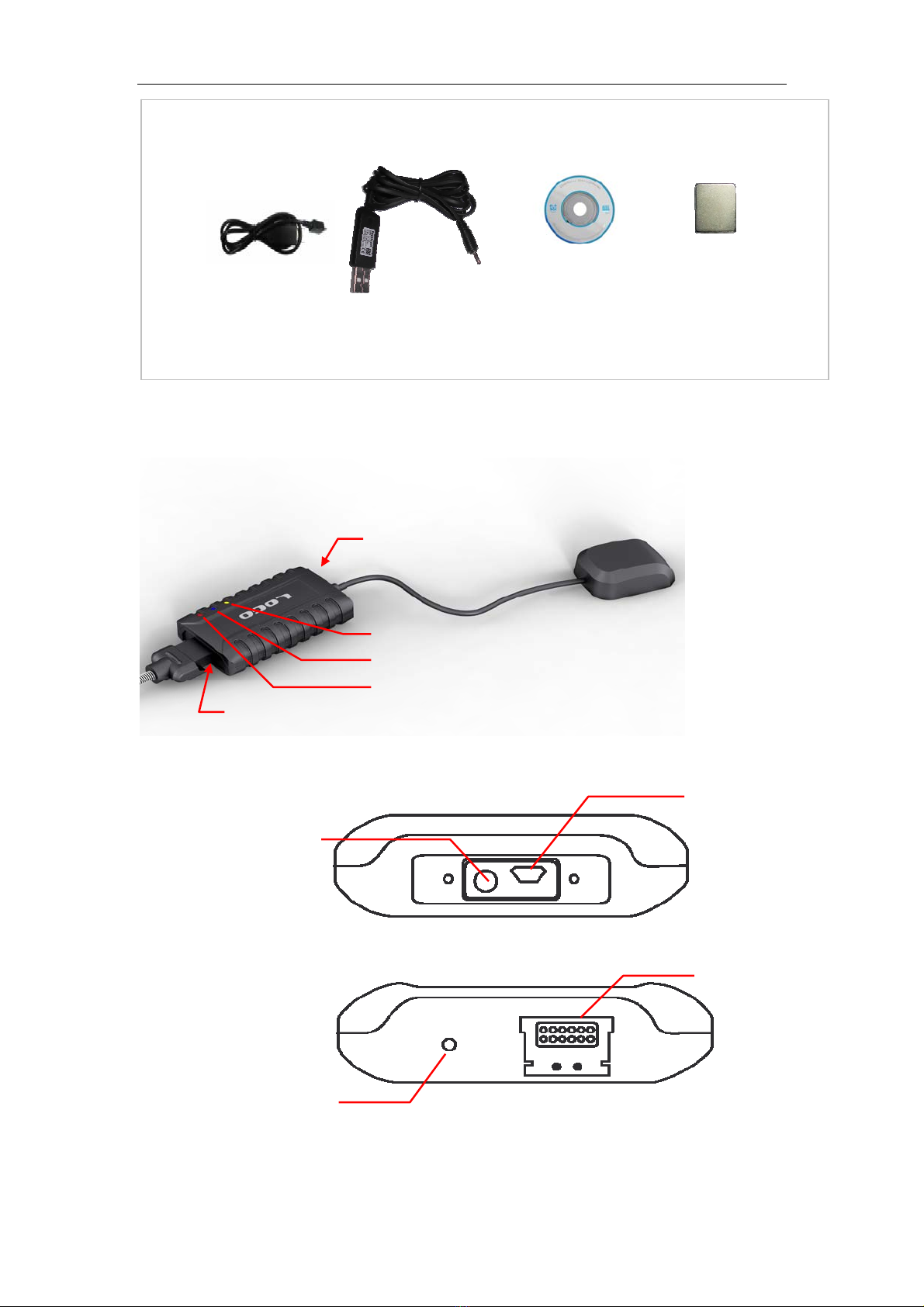
4.1 Hardware and Accessories
Tracker
(Built in battery) GPS external antenna
(Optional)
I/O connector
User Manual
- 4 -
- 4 -
4.2 Function key and Interfaces
GPS LED
GSM LED
Power LED
USB & external GPS
antenna port
I/O interfaces
CDUSB cable DC charger cable
Magnet (Optional)
I/O port:
Charging port
I/O port
USB & external antenna
port:
External antenna
connector
Micro USB port

User Manual
- 5 -
- 5 -
Red LED- Power
Always on Charging
1s on and 3s off Normally work
Blue LED- GSM
0.3s on and 0.3s off GSM module is initializing
Always on Failed to registered network
1s on and 3s off GSM module is registered network
0.1s on and 3s off GSM module is registered network
and GPRS function works well
Orange LED- GPS
0.3s on and 0.3s off GPS module initializing
1s on and 3s off GPS module works well, but GPS
position is not fixed
0.1s on and 3s off GPS module works well and GPS
position is fixed
Buttons
SOS Button Press it for 3 seconds to make a call
and/or send a SMS to authorized
numbers.
Other connectors
Switch Turn on/off tracker
GPS Antenna interface Compatible with built-in or external
antennas (optional)
SOS button
I/O connector
Power switch
SIM card holder
Built-in
MIC

User Manual
- 6 -
- 6 -
SIM Card Holder (Inside) Insert SIM card here
Mini USB Port Used for charging, firmware update,
configuration on PC
Input/Output Interface
Distinguish the inputs and outputs from color
Color PIN Function
Red VCC DC In (power input)
Input voltage: 7.5V ~ 24V/3A
Black GND Ground
Green OUT1 digital output 1, use for control relay(drive current is
500mA, max voltage: 50 v)
Yellow OUT2 digital output 2, use for control relay(drive current is
500mA, max voltage: 50 v)
Blue AIN1 Analog input 1 (input voltage: 0 ~ 3V), normally use for
Fuel Detection.
Grey AIN2 Analog input 2 (input voltage: 0 ~ 3V)
Orange SOS To connect the SOS button
Brown IN1 Digital input 1
White IN2 Digital input 2
Purple ACC Normally use for Ignition Detection.
Pink SPK+ Speaker
4.3 First Start
Please read this manual before using tracker and check if all parts are included
in the packaging box.
4.3.1 Ensure that your tracker has a working SIM card.
- Check that the SIM card has not run out of credit (Test the SIM card
in a phone to make sure it can send and receive SMS)
- Check that lock code of the SIM card is turned off.
- If you require the function of sending an SMS location report to the
authorized phone number when it makes a call to the tracker, please
make sure the SIM card installed supports displaying caller ID.
Insert SIM card:
- Unscrew the screws on front cover, as below picture shows.

User Manual
- 7 -
- 7 -
- Open the SIM holder and insert the SIM card, and turn on the power switch,
see pictures below:
- Put back the cover and screw it up tightly.
4.3.2 Use tracker as a personal tracker at first time, please charge it for 3
hours or more at turn-off state. There are 4 ways for charging: travel charger,
car charger, USB charger, and external charging (see picture below).
(Note: Please turn off the tracker when charging!)
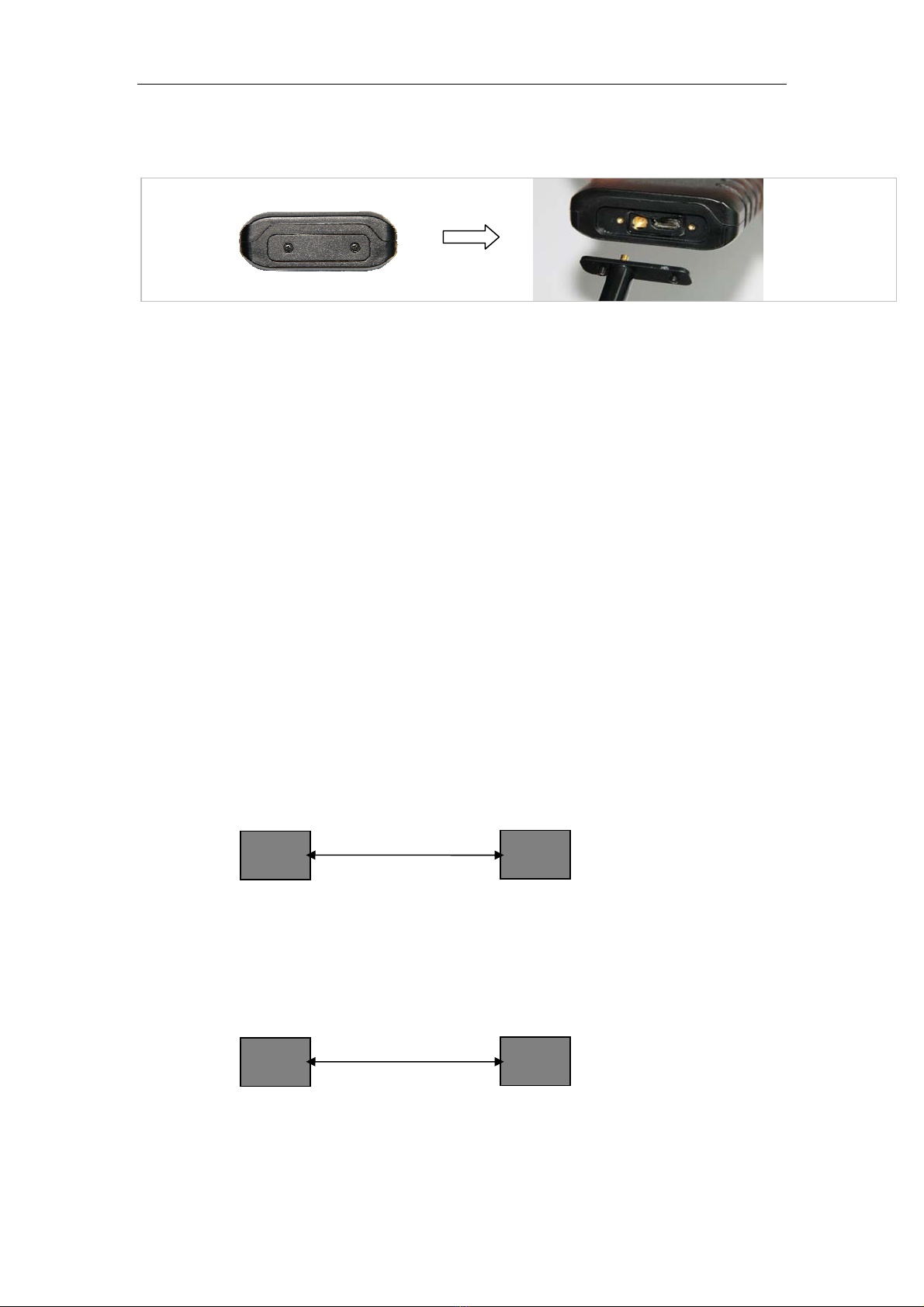
4.3.3 Connect to external antenna (optional)
Power switch
Power off Power on
Turn on power:
Open SIM holder Insert SIM card Lock SIM holder
Insert SIM card:
Computer
AC charger Car charger USB port
5V DC charger wire
External power
I/O ports
User Manual
- 8 -
- 8 -
- If users choose to external antenna, firstly unscrew the top cover and take off
the cover, then screw the customized external antenna to the tracker. See
picture below:
Note: External GPS antenna is directive antenna. It is better to fix it to face the
sky directly(to be placed under the windshield is recommended) and flat side
down, black side up, and use double-side tape to keep the antenna to avoid
effecting the GPS signal.
4.4.4 Install the tracker
Please install the tracker at a hidden place, keep those I/O wires tied up with
tape. Other wires need to be insulated by tape as well. Finally, please check I/O
wire connection and connect the tracker to external power (car power or
battery).
Note: please check the tracker LED status to confirm working normally.
5. Parameter Configuration
There are 3 ways to set parameter: set by SMS, set by PC software, set by
GPRS.
5.1 Set by SMS
Users can set the parameter of tracker by mobile phone SMS, see <command
list> from the <Communication protocol>.
Note: all commands are SMS commands in this manual.
5.2 Set by Software on PC.
Users can set the parameter of tracker by PC software; see <setup software
instruction>.
Note: Please use customized USB to serial cable or USB to serial Dongle. Do not
use any other USB cable.
PC Tracker
USB cable
Phone Tracker
SMS

User Manual
- 9 -
- 9 -
5.3 Set by GPRS.
Users can set the parameter of tracker by server, see <command list> from the
<Communication protocol>.
6. Change Password
Command: M******,00,######
Description: Change user’s password.
Note:
ALL ENGLISH LETTERS IN THE COMMAND MUST BE IN CAPITAL LETTER!
1. ****** is user’s password and the default password is 000000. Tracker will
only accept commands from a user with the correct password. Command will
be ignored if with wrong password.
2. ###### is the new password. Password should be 6 digits.
Example:
M000000,00,123456
M123456,00,888888
7. Restore Default
Command: M000000,00,RESET
Description: Factory default. It is used for forgetting the password and restoring
back to the initial password ‘000000’.
Notice: ‘000000’ in this command is fixed string, not password.
8. Authorized Number
Command: M000000,01,NO.,Phone Number,ABCDEFGHIJK
Description: Authorize phone numbers for receive SMS alarms. (See 11.1
Alarm)
Note:
NO.: should be 1 to 3.
Phone Number: Preset phone number. Max. 16 digits
A: SOS alarm
B: Help alarm
C: Call for location
D: SMS Tracking
Server Tracker
GPRS

User Manual
- 10 -
- 10 -
E: Low battery alarm
F: No GPS signal alarm
G: Geo-fence alarm
H: Over speed alarm
I: Surveillance mode
J: Vibration alarm
K: Remove off tracker alarm
(1: enable alarm, 0: disable alarm)
Example:
Preset the authorized phone number 13800000000, and just enable SOS alarm.
M000000,01,1,13800000000,10000000000
9. Tracking Via SMS
Receive the location SMS through mobile phone.
9.1 Real Time Tracking
Command: M000000,02
Description: Get the latest location
Note:
Tracker will reply back a SMS with latest location to user sent this command.
Example:
M000000, 02
You will receive a SMS as:
Lat=22 23.61N Lng=114 22.56E,MMC:460,02,CellID:27B3,0E59,
Speed=0Km/hr,05/7/2011,03:30,SMS
9.2 Google Map Link
Command: M000000,10,X
Description: set the format of SMS tracking.
Note: X=1: Set the format to be Google map link, log into the link to check the
location directly on smart phone.
X=0: Set the format as latitude and longitude
Google map SMS likes below:
CurLoc http://map.google.com/maps?f=q&hl=en&q=22.545712,114.079500
MMC:460,01,CellID:252A,07F4,Speed=0Km/h,06/23/2011,05:42,Call
Standard SMS as below:
CurLoc Lat = 22 32 44.62N Lng = 114 04 45.70E,
MMC:460,01,CellID:252A,07F4,Speed=0Km/h,06/23/2011,05:57,Call
Example:

User Manual
- 11 -
- 11 -
M000000,10,1
9.3 Tracking By Calling
Description: Any authorized number makes a call to the tracker for location and
the tracker will send its longitude and latitude by SMS. If tracker does not get
GPS signal successfully, it will reply a Google link to the authorized phone.
Note: please confirm the <call for location> function is enabled(see 8.
Authorization).
9.4 Tracking Regularly Via SMS
Command: M000000,03,X
Description: Set an interval for the tracker to continuously send its location by
SMS to authorized phone number.
Note: please confirm the <SMS tracking> function is enabled(see 8.
Authorization).
1. X is the interval in minute. (max. 65535)
2. if X=0 to turn off SMS sending at preset interval
Example:
M000000,03,30
The tracker will send location back to authorized phone number every 30
minutes.
10. Tracking Via GPRS
Receive the location data though tracking platform.
10.1 Enable/Disable GPRS
Command: M000000,21,X
Description: Enable GPRS tracking function.
Note:
X=0, turn off GPRS tracking (default)
X=1, enable GPRS tracking via TCP
X=2, enable GPRS tracking via UDP
Example:
M000000,21,1
10.2 Set Tracker ID
Command: M000000,22,ID
Description: Set tracker ID
Note:
ID, max. 16 digits

User Manual
- 12 -
- 12 -
Example:
M000000,22,123456789
10.3 APN Setting
Command: M000000,23,APN,Username,Password
Description: Set APN parameters for the tracker
Note:
1. APN username and password are optional. If no APN username and
password are required, just input APN only;
2. APN + username + password should not over 64 characters.
Example:
M000000,23,CMNET
10.4 IP and Port Setting
Command: M000000,24,IP,PORT
Description: Set IP and Port for tracker for GPRS communication.
Note:
1. IP is your server’s IP
2. Port: max. 65535
Example:
M000000,24,192.168.111.111,6000
10.5 Tracking Regularly Via GPRS
Command: M000000,25,X
Description: Set the interval for sending GPRS packets.
Note:
X: should be 5 to 65535 in second (default 30 seconds)
Example:
M000000,25,60
The tracker will send GPRS data to server every 60 seconds.
10.6 GPRS Distance Override Setting
Command: M000000,26,X
Description: Set the smallest distance for sending GPRS packets. If the distance
measured by GPS is greater than or equal to the preset distance, the tracker will
send the GPRS data to server no matter if the time is not reached at the preset
time interval.
Note:
X: 0~65535(default to be 0), unit is meter.
X=0:disable distance override
Example:
M000000,25,100
The tracker will send GPRS data to server every 100 meters no matter what time
interval set.

User Manual
- 13 -
- 13 -
10.7 GPRS Corner Sending Setting
Command: M000000,27,X
Description: Set the smallest angle for sending GPRS packets. If the angle
difference measured by GPS is greater than or equal to the preset angle, the
tracker will send the GPRS data to server no matter what time and distance
interval set.
Note:
X: 0~360(default to be 0), unit is degree.
X=0:disable corner sending
Example:
M000000,27,10
The tracker will send GPRS data to server every 10 degree corner.
11. Alarm
Detailed description of each alarm.
11.1 SOS Alarm
Description: when the SOS button is pressed for 3 seconds or more than 3
seconds, tracker will send an SMS to authorized phone number or send this
alarm to server (if GPRS connected).
Note: please confirm the <SOS alarm> function is enabled to the specific
authorized number (see 8.Authorization).
11.2 Over Speed Alarm
Command: M000000,05,XXX
Description: Turn on speeding alarm. When the tracker’s speed is higher than
the preset value, it will send an SMS to authorized phone number or send this
alarm to server (if GPRS is connected).
Note: Please confirm the <over speed alarm> function is enabled(see 8.
Authorization).
X is the preset value of speed, in Km/hr (max. 200Km/hr)
X = 0, turn off this alarm.
The preset value should be more than 50 to avoid reporting alarm too
frequently.
Example:
M000000,05,80
When the tracker’s speed is over 80Km/hr, speeding alarm will be sent out.

User Manual
- 14 -
- 14 -
11.3 Geo-fence Alarm
Command: M000000,32,NO.,name,lat,lng,radius
Description: Turn on Geo-fence alarm. When the tracker moves in/out the
preset geo-fence, it will send a SMS alarm to the authorized phone number and
send this alarm to server via GPRS.
Note: please confirm the <geo-fence alarm> function is enabled(see 8.
Authorization).
1. NO. should be 1 or 2 or 3
2. Name: max. 10 characters (ALL IN CAPITAL LETTER)
3. Lat: latitude, format is dd.dddddd. Unit is degree, pls set south latitude in
minus, .
4. Lng: longitude, format is ddd.dddddd. Unit is degree, pls set west
longitude in minus.
5. Radius: Max. 99999.00, unit is Km.
Example:
M000000,32,1,SCHOOL,22.12345,114.12345,10.50
M000000,32,2,OFFICE,12.12345,-45.12354,10.75
11.4 Vibration Alarm
Command: if the tracker is detected enough shock, it will send vibration alarm
to authorized phone via SMS and the server via GPRS if the GPRS is connected.
Note: please confirm <vibration alarm> is enabled on authorized number (see
8.Authorization). The shock strength sensitivity can be set by setup software on
PC. (see Setup Software Instruction)
11.5 Hitting Alarm
Description: when the hitting is detected by 3G-sensor, tracker will send this
alarm to server (if GPRS connected).
11.6 Low Battery Alarm
Description: if the battery of tracker is lower than 15%, it will send low battery
alarm to authorized phone via SMS and the server via GPRS if the GPRS is
connected.
Note: please confirm <low battery alarm> is enabled on authorized number
(see 8.Authorization).
11.7 No GPS signal Alarm
Description: If GPS signal is lost, tracker will send GPS signal is weak warning to
authorized phone via SMS and to server via GPRS if GPRS is connected.

User Manual
- 15 -
- 15 -
Note: please confirm <No GPS signal alarm> is enabled to the specific
authorized number (see 8.Authorization).
12. SOS Emergency Calling
Command: M000000,06,X,Num.
Description:
If press SOS button 3 seconds, tracker will call the SOS phone number.
Note:
X=1 means setting SOS number
Num: SOS phone number (max. 16 digits)
Example:
M000000,06,1,13888888888
This command will set the SOS number as 1388888888
13. Monitoring Mode
Description: when the authorized phone call the tracker, tracker will answer
automatically and the background voice sound can be heard by the authorized
phone.
Note: please confirm <surveillance mode> is enabled on authorized number
(see 8.Authorization).
14. Remove Alarm
Description: Tracker has built-in Magnetic sensor, if it keeps away from the
effective range the tracker will send remove off tracker alarm to authorized
phone via SMS and server via GPRS if the GPRS is connected.
Note: please confirm <remove off tracker alarm> is enabled to the specific
authorized number (see 8.Authorization).
15. Data Output
Description: tracker has built in 8M data logger, which is used for storing
location data of which could not be sent out via GPRS. Users can export the data
in the data logger into PC (Output file is in TXT format, see setup software
instruction).
Note: the tracker will erase the all the data that have been exported to PC, 8 M
data logger can store about 80000 data packets.

User Manual
- 16 -
- 16 -
16. Working Mode
Command: M000000,07,X
Description: Set the work mode of the tracker (mode 1 :normal vehicle &
personal mode; mode 2: personal long standby mode)
A: If the tracker is applied to vehicle, it is better to set it to be mode 1.
In mode 1: tracker will not consider saving power, all functions will normally
work.
B: If tracker is applied to persons, both mode 1 and mode 2 are selectable.
In mode 2: tracker will consider saving power for extending working time and
standby time. Please note some functions (geo-fence alarm, over speed alarm,
GPS signal is weak warming) could not normally work.
Description: When there is no task, GPS module will be off and GSM module will
be in sleep mode; When there is task(receives SMS, call or needs to send SMS
alarm, etc), the tracker will wake up GSM module and open GPS module to work.
After task is done, it will keep GSM module in sleep mode and turn off the GPS
module again.
Note:
X=0 :normal vehicle & personal mode(default)
X=1 :personal long standby mode
Example:
M000000,07,1
17. Application Examples for Inputs
17.1 Ignition Detection
Digital input 3 (ACC) can be used for ignition detection. The detection flag and
alarm (when flag changes) will be sent to the server via GPRS. Please refer to
<GPRS Communication Protocol> for more information.
Power for ignition
Ignition Switch
Car Battery
+
-
tracker
ACC

User Manual
- 17 -
- 17 -
17.2 Fuel Detection
Analog input1 (AIN1) can be used for fuel detection. The remaining-fuel-percent
will be sent to the server via GPRS. Please refer to <GPRS Communication
Protocol> for more information.
18. Output Control
18.1 Output Command
Command: M000000,50,NO.,X
Description: This command is to enable/disable the status of tracker.
Note:
NO. should be 1 or 2 (‘1’ refer to output 1, ‘2’ refer to output 2.)
X=1 to open the output, it can drive a relay.
X=0 to close the output.
Example:
M000000,50,1,1
VCC
AIN1
GND
Table of contents
Other MEGASTEK GPS manuals


