Megatank GEH Series User manual

Power your quality life
GEH Series All-in-one ESS
GT Powertank
Installation Manual

MENU
1. Introduction
2. Safety Guidelines
3. Do's & Don'ts
4. Installation Tools
5. System Components
6. Wiring Guide
7. Installation Guide
....................................................................
.............................................................
...................................................................
.............................................................
.........................................................
....................................................................
.............................................................
03
03
04
04
05
07
08
02

1. Introduction
1.1 Welcome to the ever-increasing family of satised MEGATANK users. All MEGATANK products like the one you have
just purchased, undergo a stringent quality check. This instrument provides clean and reliable power to your Load
and peripherals and protects them from blackouts. The product is designed to provide you an ecient performance
with only minimal care and maintenance at your end. This manual will facilitate you to not only understand the basic
working of the ESS but will also facilitate the ease of its maintenance and use.
1.2 MEGATANK all in one ESS provides power to fans, bulbs, computers etc.
1.3 System diagram is as below:
2. Safety Guidelines
Please go through these guidelines before connecting the product.
2.1 Always connect the ESS to a two-pole, three-wire grounding Mains socket. The socket must be connected to
appropriately protected branch of the Mains (fuse/circuit breaker). Connection to any other type of socket may result
in a shockhazard.
2.2 To Switch o the ESS output in an emergency, use the touch switch on graphic display to switch the ESS o. Turn the
battery switch OFF on the back to disconnect the battery module.
2.3 Avoid Installing the ESS in an excessively humid place or where there is water. Care must be taken to ensure that
the ESS is kept away from heat emitting appliances such as a heater, blower, oven etc. The unit must also be placed
in a manner that it avoids exposure to direct sunlight. The place of installation should be well-ventilated and easily
accessible for servicing.
2.4 Foreign particles and water must not enter the ESS. Always ensure that no objects containing a liquid are ever kept
near the unit.
2.5 Don't allow any spark near battery modules.
2.6 Always switch o the product, disconnect mains & turn o AC/DC MCB while inserting or replacing the battery
modules.
2.7 Do not open the product, there are dangerous high voltages inside even when power is o, contact the company if it
is not working properly.
03

3. Do's & Don'ts
4. Installation Tools
3.1 DO'S —— Do's related to Megatank
Unplug and switch o the product before other material it may result in re hazard.
Wear safety gloves and goggles.
Install product in proper ventilated area.
Keep out of reach of children.
Insert the battery modules considering the orientation of side panel connector.
3.2 DON'TS —— Don'ts related to Megatank
Don't block the side ventilation slots by cloth or touching or cleaning the surfaces.
Don't place the product near radiation or heat source.
Don't install the product near kitchen sink, laundry, wash bowl, bath tub.
Don't keep product near a moisture area or in direct sunlight.
Never short the terminals of the battery modules.
Keep away ammable things from the battery modules.
Don't dispose of battery modules in re.
Don't open or mutilate batteries modules.
Heavy-duty Hammer Drill
2.5mm Hex Wrench
Hammer
Box Cutter
Insulated Flat Screwdriver 2.5mm
9mm Drilling Bit
Hot Air Gun
Safety Insulating Glove
Marker Pen
Insulated Philips Screwdriver PH2
Multimeter
Multifunction Stripping Piler
Socket Wrench 10mm
Measure Tape
04

5. System Components
Main Components List
No Name Picture Qty Description
1 Power Module 1pcs
The power switch button is located on
the back of the power module.
The wiring window is located in the
middle of GE device. The antenna is on
the top-right of the Power Module.
The carrying handle is located on both
sides of the Power Module.
2Battery Module
1 pcs (GE0605H)
or
2 pcs (GE0610H)
The wiring interface is on top of the
battery.
The breaker is on the back of the
Battery Module.
3Power Module
Cover (With screen) 1pcs
To cover with the Power module.
Take more details from product
manual.
4Battery Module Cover GE0610H: longer cover
GE0605H: shorter cover To cover with the Battery module.
Package of accessories
05

Main Accessories List
No Name Picture Qty Usage
1Communication cable
1800mm 1pcs To connect with GT Wi router device and
local Wi.
2Communication cable
850mm 1pcs To connect with battery module 1 and
battery modul 2.
3Battery module
negative power cable 1pcs To connect with battery module and busbar.
4Battery module
positive power cable 1pcs To connect with battery module and busbar.
5M6 x 50
sleeve anchor 6pcs To x the bracket on the wall.
6M4 x 10 Screws 8pcs To connect with the bracket and battery
module.
7Fixed clips 14pcs To connect with the cover and device
8 Long ground cable 1pcs To connect with the battery and power
module
9 Short ground cable 1pcs To connect with the battery1 and battery2
10 Wake up cable
1 in 2 out 1pcs To connect with power to battery1 and
battery2
11 Lug 1pcs For power module to ground heat
shrinkable
12 Hanging lug 4pcs To connect with battery module and wall-
mounting bracket
13 Wall-mounting
bracket 2pcs To mount the battery module on the wall.
14 Power module
wall-hanging bracket 2pcs To connect with power module and wall-
mounting bracket.
15 Wall-mounting
bracket 1pcs To mount the power module on the wall.
16 CT connector 1pcs To connect with grid CT and the inverter.
17 PV connectors
(2*positive) 2pcs To connect with inverter PV +.
18 PV connectors
(2*negative) 2pcs To connect with inverter PV -.
19 PV pin connectors
(2*positive) 2pcs To connect with PV connector +.
20 PV pin connectors
(2*negative) 2pcs To connect with PV connector -.
21 AC terminals 2pcs To connect with AC.
22 Network cable
connector extender 1pcs To connect with the communication cable
and CT.
23 WIFI router 1pcs To connect with Wi router and local LAN
24 Adapter plug 1pcs For local AC plug.
06

6. Wiring Guide
07

7. Installation Guide
7.1 Install the slave battery module
7.1.1 Prepare wall mounting tools and accessories required.
M4 X 4 M6 x 50 Sleeve anchor
Hammer Drill (9mm)
Insulated Philips Screwdriver PH2
7.1.2 Locate the wall studs in the desired location and align it. Connect with the bracket, x the wall-mounting bracket on
the wall.
08

7.2.2 Set the top master battery GL48100C address is 1000 (ON-OFF-OFF-OFF). Connect the communication cable from
slave battery RS485-1 to the master battery RS485-1. Connect the wake up cable from slave battery wake up port to
7.2 Install the master battery module
7.2.1 Install master battery module on the slave battery. As per before slave battery bracket installation, x the wall-
mounting bracket on the wall.
master battery wake up port.
7.1.3. Set the bottom slave GL48100C battery address is 0100 (OFF-ON-OFF-OFF). Connect the cables as below.
Positive cable
to bus bar (+)
RS485-1 to master
battery RS485-1
Slave battery
Master battery
Wake up cable
to master battery
Negative cable
to bus bar (-)
09

7.3 Install the power module
7.3.1 Mark the 2 mounting-hole positions. Use a hammer-drill to drill two holes. Install the power module wall-mounting
bracket to the wall.
7.3.2 Install the power module on the top of master battery.
10

Connect the positive cable from busbar to master battery positive port (orange), negative cable to negative port
(black);
Connect G2-BMS-INV-COM cable to CAN port;
Connect G2-BMS-EMS-COM cable to RS485-2 port.;
7.3.3 Connect the slave battery positive cable to busbar (+), the negative cable to busbar (-);
Connect the battery wake up 2 out 1 in wire to power module wake up.
7.3.4 Connect the short ground cable from slave battery to master battery;
Connect the long ground cable from mater battery to power module.
Busbar + Busbar -
CAN RS485-2
battery negative cable
battery positive cable Wake up connection
11

7.4 Install the cover of system
7.4.1 Open the cartoon-box, take the below covers out.
7.4.2 Install the bottom cover to the slave battery.
7.4.3 Connect the bottom cover wire and power module wire to LED
port.7.4.4 Install middle cover and top cover to the whole system. 7.4.5 Use the clip to x the cover on the back side.
12

7.5 Test the system
7.5.1 Make sure all cables are tightly connected. Battery switch is in the back of module. Take 2 battery modules switch
as on, then turn power module on.
7.5.2 If everything is connected properly, LED light will be on and all datas are normal.
13

7.6 The external wiring diagram
7.6.1 Before connecting PV and EPS, make sure all switches are OFF. Connect the PV and EPS as below.
7.6.2 Once PV is installed properly, turn PV switch on.
EPS
GRID
Object Description
A/B Battery+ / Battery-
C/D PV1+ / PV1-
J/K PV2+ / PV2-
EDC Switch
FWIFI port for external WIFI
L Reserved port
GDRM / BMS
H Grid current / DRY IO
MUSB port for upgrading
N POWER CAN / LEAD-NTC
I Pressure Valve
OEPS output
P Grid output
14Company: Shenzhen GT Powertank Co., Ltd. Website: www.gt-ess.com Mail: [email protected] Telephone: +86-755-8657 6248

7.7 Connect the Wi router
7.7.1 Open the GT Wi router package, connect to the power. Use plug adaptor if in need.
Communication cable 1.8m
7.7.2 Connect GT Wi router WAN port to the local WAN/LAN port.
15 Company: Shenzhen GT Powertank Co., Ltd. Website: www.gt-ess.com Mail: [email protected] Telephone: +86-755-8657 6248

Shenzhen GT Powertank Co., Ltd.
www.gt-ess.com
+86 755 8657 6248
Operation Center: Room 202, Building 4, Wisdomland Business Park, No.2 Nantouguankou Road,
Nanshan District, Shenzhen, Guangdong, China, 518000.
Production Center: 205 Taihao Technology, No. 5, Guansheng Road 5, Luhu Community, Guanhu
Street, Longhua District, Shenzhen, Guangdong, China, 518000.
Table of contents
Other Megatank Storage manuals
Popular Storage manuals by other brands
Sealey
Sealey APMS Series instructions

Arrow Storage Products
Arrow Storage Products ED108 Owner's manual & assembly instructions

Tesla
Tesla POWERWALL 2 AC installation manual
Tandberg Data
Tandberg Data Storage Library T24 installation instructions

Western Digital
Western Digital WD3001HKHGSP Specifications
QNAP
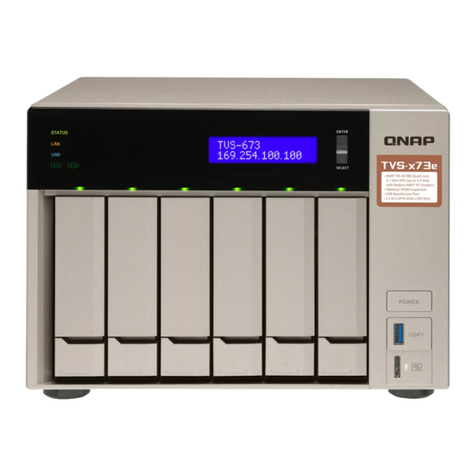
QNAP TVS-73e Series Quick installation guide
