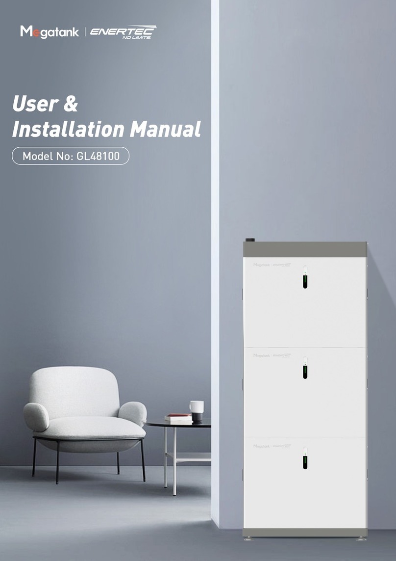
Megatank GL48100 User manual

Residential Battery Storage System
Opreation Manual
Model No: GL48100 | Version: V1.0
Shenzhen GT Powertank Co., Ltd.
Shenzhen
Headquarters
Shenzhen GT Powertank Co., Ltd.
www.gt-ess.com
(+86) 755 8657 6248
Room 208, Building 30, Wisdomland Business Park, No.2 NantouguankouRoad, Nanshan
District,Shenzhen, Guangdong, China, 518000.

Shenzhen GT Powertank Co., Ltd. www.gt-ess.com (+86) 755 8657 6248 GT Powertank, Power your quality life
No. Name Picture Qty
①Wall-mounting bracket 2
②Sleeve anchor
M6*50 4
③
Phillips screws with spring
washer and flat washer,
button head: M4*10
6
1.General instructions
This operation manual includes essential instructions for a GL48100 residential energy storage system
manufactured by Shenzhen GT Powertank Co ., Ltd. The instructions include installation & wiring guide/
battery address setting/communication protocol choosing and battery maintenance method.
Please read this manual carefully before any installation.
2.Check the accessories
Before the installation, please check all the accessories in the package. The optional accessories will be
packed only if a user purchases them.
The parallel operation cables will not be included if a user chooses only one GL48100. If a customer
purchases multiple GL48100s and confirms the parallel configuration with GT Powertank staff, GT will
pack parallel operation cables with GL48100s .
Due to the actual operation environment varies, a installer needs to prepare the power & communication
cables between the inverter and GL48100 by himself.
2.1 Default installation accessories
2.1.1 One GL48100 flooring-mounting accessories
Table of Contents
No. Name Picture Qty
④
Battery cable
connector
(Orange)
1
⑤Battery cable
connector (Black) 1
⑥Default Ethernet
cable(1.8m) 1
⑦Battery base 1
(Optional)
Part 1
Part 2
Part 3
Part 4
General instructions
Check the accessories
Installation guide
Choose the GL48100 internal communication protocol
2.1 Default installation accessories
2.1.1 One GL48100 flooring-mounting accessories
2.1.2 Wall-mounting accessories- One GL48100
2.2 Double GL48100s Floor-mounting accessories for parallel operation
2.3 Triple GL48100s Floor-mounting accessories for parallel operation
3.1 Floor-mounting installation
3.2 Wall-mounting installation
4.1 Prepare the tools
4.2 Wiring diagram
4.3 How to operate the monitor software
Appendix 1
Appendix 2
03
03
03
03
04
05
06
07
07
16
18
18
18
19
22
23
02 03

Shenzhen GT Powertank Co., Ltd. www.gt-ess.com (+86) 755 8657 6248 GT Powertank, Power your quality life
2.1.2 Wall-mounting accessories- One GL48100 2.2 Double GL48100s Floor-mounting accessories for parallel operation
No. Name Picture Qty
①Wall-mounting
bracket 1 1
②Wall-mounting
bracket 2 2
③Sleeve anchor
M6*50 7
④
Phillips screw with
spring washer and
flat washer, button
head M4*10
2
No. Name Picture Qty
①wall-mounting
bracket 4
②Sleeve anchor
M6*50 8
③
Phillips screws with
spring washer and
flat washer, button
head M4*10
12
④GL DC junction
Box 1
⑤
Parallel operation
Ethernet
cable(0.75m)
1
⑥Default Ethernet
cable(1.8m) 1
No. Name Picture Qty
⑤
Phillips screws with
spring washer and
flat washer, hex
head M6*12
2
⑥Default Ethernet
cable(1.8m) 1
⑦Battery cable
connector (Orange) 1
⑧Battery cable
connector (Black) 1
No. Name Picture Qty
⑦
Short battery
positive power
cable (0.42m)
1
⑧
Short battery
negative power
cable (0.48m)
1
⑨
Middle battery
positive power
cable (0.85m)
1
⑩
Middle battery
negative power
cable (0.93m)
1
⑪Battery base 1
(optional)
Top GL48100
Bottom GL48100
04 05

Shenzhen GT Powertank Co., Ltd. www.gt-ess.com (+86) 755 8657 6248 GT Powertank, Power your quality life
Step Picture Description
1.Install wall-
mounting bracket
on the battery
back with screws
Every GL48100 includes
①Wall-mounting bracket 2pcs
②Phillips screws with spring washer and flat washer,
button head M4*10 6pcs
Tool:
Philips screwdriver
2.Insert cable tie
Please prepare the
cable tie by yourself
Cable tie: Recommended
3.6mm(W)*200mm(L)
3.Put battery base
close to a wall 1. The height of this battery base is adjustable.
2. The minimum height from the top surface of this
battery base (the positioning cylinder is not included)
to the ground is 60mm.
4.Put GL48100 onto
its battery base, let
the mounting
bracket close to
the wall
1)Put the positioning
hole on top of the
positioning cylinder
2)Make sure the
GL48100 is on a
horizontal plane,
adjust the battery
base’s feet if
needed
5.Mark bottom
GL48100 drilling
hole
Use a marker to mark
two drilling holes
Make sure the marker is
in the middle of the two
holes Remove GL48100
& its battery base aside
1)The drilling holes’ marker should consider the the
battery metal base height and the battery base’s foot
height.
2)If the ground is flat, please refer below diagram to
mark the drilling hole.
①The unit is mm
②The two-hole distance of the wall-mounting bracket
is 60mm
③The wall-mounting brackets left & right mounting
hole distance is 200mm
④The height between the drilling hole& battery base top
surface is 451mm±2mm
⑤The height from the battery base t to the ground
is h. h ≥ 60mm. Please consider the battery base
foot-stand‘s height to confirm the h value.
2.3 Triple GL48100s Floor-mounting accessories for parallel operation
No. Name Picture Qty
①wall-mounting
bracket 6
②Sleeve anchor
M6*50 12
③
Phillips screws with
spring washer and
flat washer, button
head M4*10
18
④GL DC junction
Box 1
⑪
Parallel operation
Ethernet
cable(0.75m)
2
⑫Default Ethernet
cable(1.8m) 1
No. Name Picture Qty
⑦
Short battery
positive power
cable (0.42m)
1
⑧
Short battery
negative power
cable (0.48m)
1
⑨
Middle battery
positive power
cable (0.85m)
1
⑩
Middle battery
negative power
cable (0.93m)
1
⑪
Long battery
positive power
cable (1.28m)
1
⑫
Long battery
negative power
cable (1.38m)
1
⑬Battery base 1
(optional)
3.Installation guide
The floor-mounting installation guide is based on triple GL48100 parallel operation, with its DC junction
box and related power cables & Ethernet cable.
The wall-mounting installation guide is based on one GL48100.
3.1 Floor-mounting installation
The position cylinder
The positioning hole
Top GL48100
Middle GL48100
Bottom GL48100
06 07

Shenzhen GT Powertank Co., Ltd. www.gt-ess.com (+86) 755 8657 6248 GT Powertank, Power your quality life
10.Install the middle and top GL48100
1)Refer to step 1&2, install the middle &
the top GL48100 on the wall.
2)Put the top GL48100 on top of the
middle GL48100. Tighten them one
by one using sleeve anchors.
11.Open GL DC junction box top cover
1)There are four screws on the junction
box cover.
Please remove two screws on its
backside cover as spare parts.
2)The screws are already installed on
the bus bar like ②.
3)Use two screws in a small plastic
package to tighten GL DC junction
box on top GL48100.
Screw size: M4*16, Stainless steel with spring washer; Tool: Philip screwdriver
Screw size: M6*12 Stainless steel with a spring washer & a flat washer
Tool: No. 10 socket wrench or Philips screwdriver
Screw size: M4*10, Stainless steel with spring washer
Tool: Philips screwdriver
6.Mark top & middle
GL48100 the drilling holes
Check the left diagram to mark
the top & middle GL48100
drilling holes
Note:
1)Make sure all the horizontal and
vertical measurements are accurate.
A wrong measurement offset may
affect the top & middle battery position.
2)The middle & top GL48100 drilling
holes positions are based on the
bottom hole position.
7.Drill the holes
We recommend using the No.
9 drill bit to drill the holes. The
expansion blot sleeve is 35mm
①, the depth of a hole should
be 40mm, less than 50mm.
8.Put expansion bolts into
the drilled holes.
Please remove the screw nut
and washers on the expansion
bolt. Use them to tighten the
GL48100 battery metal case
later.
9.Tighten the battery metal
case with sleeve anchor
Tighten the battery case on
the wall by the sleeve anchors
②and washers by a socket
wrench ③.
The sleeve anchors are fixed
into the wall with the GL48100
metal case.
Note:
1)The No. 10 (Φ10mm) drill bit is too
big for the M6*50 expansion bolt.
2)The No. 8 (Φ8mm) drill bit is too
small for M6*50 sleeve anchor.
DO NOT try to hammer the anchor in.
3)Please refer to D as your drill bit size.
Sleeve Anchor specs
304 Stainless steel M6*50;
Sleeve Anchor qty
12pcs
Tool:
Open-end wrench or 10mm socket wrench
M6*50 expansion bolt sleeve
Remove two screws as spare parts
Pre-installed screws
①
①
④
③
③
②
②
Sleeve Anchor
08 09

Shenzhen GT Powertank Co., Ltd. www.gt-ess.com (+86) 755 8657 6248 GT Powertank, Power your quality life
12.Connect the power
cables into the GL DC
junction box
* We call them top GL48100/
middle GL48100/ bottom
GL48100
1)Please refer to the right
diagram to connect all the
short/middle/long power
cables.
Triple GL48100 in parallel:
Double GL48100 in parallel:
Top
GL48100
Top
GL48100
Middle
GL48100
Bottom
GL48100
Bottom
GL48100
Battery
System Power cable Length Color
To p
Positive power cable short 0.42m orange
Negative power cable short 0.48m black
Middle
Positive power cable middle 0.85m orange
Negative power cable middle 0.93m black
Bottom
Positive power cable long 1.28m orange
Negative power cable long 1.38m black
Battery
System Power cable Length Color
To p
Positive power cable short 0.42m orange
Negative power cable short 0.48m black
Bottom
Positive power cable middle 0.85m orange
Negative power cable middle 0.93m black
2)Please refer to the left to connect
the cables onto the negative &
positive copper busbar with some
loose screws, no need to tighten
them at this moment
* Note:
a.Please refer to the order on the
left to connect these power cables
b.Leave the left & right connecting
joints on the busbar disconnected.
DO NOT connect cables on them.
Note:
a.The power cables to the inverter or other battery sets are not shown in the
above picture. The power cable dimension between an inverter and this busbar
should match the inverter’s continuous current value. DO NOT use GT’s
parallel power cable dimension as reference.
b.The battery connector for the negative & positive joint is SC25-6(for 25mm² cable)/
SC /SC35-6(for 50mm² cable/50-6 (for 50mm² cable) or similar sizes as them.
c.Cable temperature resistant 125°C or higher,
Flammability rating VW-1 or UL94-V0.
3)install the power cable between
this battery set and inverter/
another battery sets
13.Install the GL DC junction box
1)Use step 11-3) screw M4*10 to install
the GL DC junction box onto the top
of GL48100
2)Please refer right picture to manage
the backside power cables.
Put the power cables on the outside of
the mounting bracket.
Long negative cable
Long positive cable
Inverter / other battery negative set joint Inverter / other battery set positive joint
Negative
copper busbar
Positive
copper busbar
Middle negative cable
Middle positive cable
Short negative cable
Short positive cable
Screw size:M4*10 with
spring & flat washer
Mounting bracket Negative power cables
10 11

Shenzhen GT Powertank Co., Ltd. www.gt-ess.com (+86) 755 8657 6248 GT Powertank, Power your quality life
18.GL48100 address
We use address switches to
configure different GL48100
addresses.
The top/middle/bottom battery
addresses are 1000/0100/1100
Please refer to Appendix I to
configure the addresses if more
than one GL48100s need to be
connected into a parallel energy
storage system.
Note:
The master address
1000 is responsible
for communication
with an inverter.
1)Please configure the address switch when the GL48100 is power off.
2)When the switch is on the “ON” position, it means 1. Here is the address table for
three GL48100 parallel operating system. Please refer to GL48100’s user manual
for more details.
19.connect the communication
cable to an inverter
Use a 1.8m default
communication cable to
connect the master battery and
its inverter.
Use ④CAN/RS482-2 port.
There are two identical ports
at ④
Note:
1)Please refer to the Pin
definition on the right
a.Pin4 - CANH
b.Pin5-CANL
c.Pin 1&8 - B
d.Pin 2&7 - A
2)The inverter’s BMS
communication port pin’s
definition might differ
from GL48100’s CAN/
RS485-2 pin definition.
If so, please use
an Ethernet cable to make
a special communication
cable
pin
1)CAN/485-2 Port Definition:
2)When inverter’s BMS communication definition is different from GL48100’s
CAN/485-2 pin definition.
a. Cut off one end of the ethernet cable by a scissor
b. choose CANH&CANL
well taped the wires.
b. Or choose one pair of
RS485A and RS485B
* We recommend use CAN port as the communication port.
Connect inverter BMS communication port to GL48100 CAN/485-2
b. CAN communication: please
refer the inverter’s BMS Pin
definition, wire the CANH &
CANL into correct pin
position in RJ45 connector.
c. RS 485 communication:
push RS485-A & RS485-B
into their pin position in
RJ45 connector.
14.Open the side covers on the left and
right sides of GL48100
Make sure the power button & circuit
breaker is off.
Tool: Philips screwdriver
15.Connect the power cable
1)Connect the power cable connector into
the positive/negative ports. ②
2)Tighten the screws on the
busbar(Tighten Torque: 5.5±0.5Nm or
55±5kgf.cm) put the excess cable length
on the left.
Use a cable tie to organize these cables.
Note:
The power cables to the inverter or other battery set are not shown in the
above picture.
Please make sure the screws are tightened with the busbar. If the screws are
loose, it may cause overheating problems or safety accidents.
16.Install the DC junction box top cover
Please tighten the screws on both sides of
the DC junction box.
Please refer to step 11-1
17.Install the parallel communication cable
The length of the parallel communication
cable length is 0.75m. Its port is “RS485-1”,
please refer to ⑥on the left.
Note:
a.There are two identical ports at ⑥for
communication in or out.
b.If there are more than one battery sets need
to be connected in parallel. Please refer to
Appendix I for cable connections.
c.If needs to change the internal inverter
communication protocol, please refer to
chapter 4 and switch the needed
protocol before connecting a
communication cable.
Use a cable tie to organize the communication
cable.(Please refer step 2 above)
Put the excess cable length in the left.
Tighten Torque:5.5±0.5Nm(or 55±5kgf.cm)
①
②
③
12 13

Shenzhen GT Powertank Co., Ltd. www.gt-ess.com (+86) 755 8657 6248 GT Powertank, Power your quality life
22.If the GL48100 system works
fine, please install the
handle covers on both sides.
The GL48100 installation is
done.
23.Additional info.
Wire the GL48100 to ground
The bottom port (in right
circles) is designed for ground
connection.
The electrician will decide
whether connect GL48100 to
the ground or not according to
the installation needs.
The ground cable is not included
in GL48100’s package.
20.Confirmation
1)Make sure all power cables are
connected in the right order
(step12-2).
2)Make sure the inverter’s power
cable size and battery connector
size is correct, refer to step 12-3.
3)Make sure the screws in the DC
junction box are tightened. Please
refer to step 15-2.
4)Make sure the parallel
communication cables are
connected to the correct port
and a proper communication
protocol is chosen.
5)Make sure all address switches
on all GL48100 are configured
correctly. Please refer to step 18.
6)Make sure the communication
cable between the master
GL48100 and the inverter works
fine. Please refer to the cable
connection guide one left.
* Please refer to appendix 1
to see how to wire multiple
GL48100s.
21.The inverter settings & system trial operation test
Now all three GL48100s are wired with the inverter’s power and communication cables. Do not connect unitality grid AC
input into this system.
1)Please refer to the GL48100 user manual to configure the discharging/charging parameters on the inverter.
2)Turn on GL48100 in the following order
a. Turn on the circuit breaker on all GL48100.
b. Turn on the Master GL48100’s power button.
c. Turn on the rest of GL48100’s power button if everything works fine.
3)Connect the loads one by one to check the running status.
a. Check GL48100’s status on its inverter, (e.g., battery quantity, charging/ discharging current/ voltage request value,
SOC, fault state). A technician can use an upper computer to monitor the GL48100’s status if he/she is authorized by
Shenzhen GT Powertank Co., ltd.
b. Confirm there is no abnormal phenomenon during GL48100 charging/discharging process.
14 15

Shenzhen GT Powertank Co., Ltd. www.gt-ess.com (+86) 755 8657 6248 GT Powertank, Power your quality life
Steps Picture
1.Mark GL48100 drilling holes
Refer to the diagram on the right to
mark the drill hole.
Please make sure all the measurements
are accurate, including size/levelness/
verticality)
h is the height between the drilled hole
and ground, (h-74)mm is the height
between GL48100 and the floor.
Don’t set this h dimension too high
because GL48100 is heavy. It is not
easy to lift it to a high place.
2.Drill the holes
We recommend use No. 9 drill
bit(Please refer to chapter 3.1 –
step 7 )
3.Put the expansion bolt into
the drilled hole.
Please remove the screw nut and
washers on the expansion bolt.
Keep them to tighten the GL48100
battery metal case later.
4.Install the wall-mounting
bracket 1
Refer to the left diagram to install
the wall mounting bracket 1 by an
open-end wrench or 10mm
socket wrench
5.Install wall-mounting bracket 2
Use M4*10 with spring washer& flat
washer to tighten the wall-mounting
bracket 1 & bracket 2.
Lock and tighten the sleeve anchors,
then tighten the M4*10 screws in
the right red circles.
* Please do the above two steps one
by one. Otherwise, the following
steps might face a problem.
3.2 Wall-mounting installation
7.Open the covers on both sides
of GL48100
Please refer chapter3.1-step 14 / step 17/ step18 & step 19
8.Make the power cable
between GL48100 and the
inverter
After the length between the
GL48100 and inverter is measured,
please make the power cable using
this length. The power cable size:
①25mm²(or 4AWG) ②16mm²(or 6AWG)
②Temperature continuously usage >125°C
Recommended flammability standard:VW-1 or UL94-V0
Note:
①4AWG cable size is smaller than 25mm², cable, please use hydraulic crimping tool
25mm2dye to crimp the wire and make sure it is tight.
②6AWG cable size is smaller than 16mm2, cable , please use hydraulic crimping tool
16mm2dye to crimp the wire and make sure it is tight.
9.Make the communication cable
After the length between the
GL48100 and inverter is measured,
please make the power cable using
this length.
Please refer to chapter 3.1- step19 for cable-making details.
Communication cable needs
CAT-5E or higher Ethernet cable. The port on the GL48100 is RJ45.
10.Please refer to chapter 3.1, step 21, to connect the communication cable, configure the inverter parameters, run a trial
operation test.
11.If the trial operation test is OK, install the two-side handle covers. GL48100’s installation is done.
If multiple GL48100s need to be mounted on the wall, please refer to Appendix 2 as the wiring guide.
6.Lift and hang the GL48100
onto the wall-mounting
brackets.
The whole battery case is hanged
on wall-mounting bracket 1
(red rectangles on the right.)
Use hex head M6*12 screws( with
its spring and flat washers) to hang
the battery metal case terminal to
wall-mounting bracket 2
* Use battery metal case terminal
to connect the ground wire.
Wall-mounting bracket 2
16 17

Shenzhen GT Powertank Co., Ltd. www.gt-ess.com (+86) 755 8657 6248 GT Powertank, Power your quality life
4.3 How to operate the monitor software
1.Open the monitor software’s monitor tab
a.Chooses correct serial port( refer 4.1-1 the COM port in Windows device manager.)
b.Click Starting. The monitor software will configure the baud rate and try to connect GL48100. Wait for a
few seconds.
c.Make sure the connection is successful. If the GL48100’s address is configured before, click its address to
enter the battery information page.
The default address is 0 if the battery address is not configured. The monitor software’s bottom “comm
status” status bar blinks and displays Write communication pr… GL48100 detailed info will be displayed if
every step is corrected.
2.Choose the inverter protocol
1)Click Software settings
4.Choose the GL48100 internal communication
protocol
GL48100 is compatible with multiple brand’s communication protocols on the market. The default
communication protocol is the most-used one. If there are any abnormal communication issues during
the usage, please request an authorized technician’s help to choose the correct communication protocol
through GT’s upper computer monitoring software.
4.1 Prepare the tools
1)Prepare a computer with pre-installed USB to RS485 communication tool driver.
a.Please refer to the USB-RS485 communication tool’s installation guide to install the driver.
b.Please confirm the Window Device Manager can show the correct COM port after the driver
installation is done.
c.Please use the Windows operating system only.
2)USB to RS485 communication tool & Ethernet cable
a.Use one end of an Ethernet cable with RJ45 connector, refer to chapter 3.1 step 19 to choose RS485
A and RS485 B wires, and connect them to the USB to RS485 communication tool’s A/B connect pins.
b.Use the electrical insulation tape to wrap the cable.
3)Use GT battery monitor software
4.2 Wiring diagram
1)This is a schematic diagram.
2)When all the wires are connected, please power on GL48100.
18 19

Shenzhen GT Powertank Co., Ltd. www.gt-ess.com (+86) 755 8657 6248 GT Powertank, Power your quality life
2)Enter the Software settings tab
3)Click Read to show the default parameters
4)Click the CAN or RS485 protocol drop-down menu
5)Choose inverter brand’s communication protocol and click Write(Picture 5)
6)After the writing process is done, the software will pop up a small window, then click read to
confirm(Picture 6)
(Picture 5) (Picture 6)
7)The protocol choosing step is done.
Please refer to chapter 3.1 -step 19, connect GL48100 to its inverter and check if GL48100’s battery
information is correctly displayed on the inverter screen. Use GT’s monitoring software to read the
accurate battery data if needed.
8)Please refer above steps to choose the communication protocol for the rest of GL48100s.
20 21

Shenzhen GT Powertank Co., Ltd. www.gt-ess.com (+86) 755 8657 6248 GT Powertank, Power your quality life
Appendix 1
1)Above diagram show multiple sets of GL48100s parallel operation solution. However, it is not the best
solution.
2)If possible, the power cable length from every battery set to the inverter should be the same.
Otherwise, each set's charging / discharging current will have some difference, which leads to bad
effects on the battery’s performance.
3)Each battery set’s communication cable’s topological structure should be bus type. Please use the master
battery set as the middle point.
If one GL48100 lost its communication with the inverter, please try to add a 120Ω terminal resistance or a
repeater.
4)If the parallel operation battery’s quantity is more than 9, please contact GT Powertank for a customized
solution.
Appendix 2
Above is the wiring diagram for multiple GL48100 wall-mounting parallel operations.
5)If possible, the power cable length from every battery set to the inverter should be the same.
Otherwise, each set's charging/discharging current will have some difference, which leads to bad effects
on the battery’s performance.
6)Each battery set’s communication cable’s topological structure should be bus type. Please use the
master battery as the middle point. If there is one GL48100 that lost its communication with the
inverter, please try to add a 120Ω terminal resistance on it.
7)For wall-mounting GL48100, we do not recommend operate them in parallel.
22 23
Other manuals for GL48100
2
Table of contents
Other Megatank Storage manuals
Popular Storage manuals by other brands
Sealey
Sealey APMS Series instructions

Arrow Storage Products
Arrow Storage Products ED108 Owner's manual & assembly instructions

Tesla
Tesla POWERWALL 2 AC installation manual
Tandberg Data
Tandberg Data Storage Library T24 installation instructions

Western Digital
Western Digital WD3001HKHGSP Specifications
QNAP
QNAP TVS-73e Series Quick installation guide
