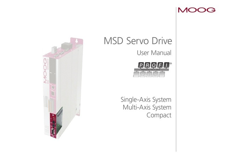
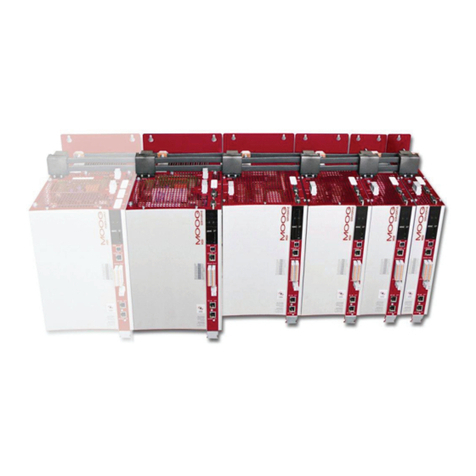
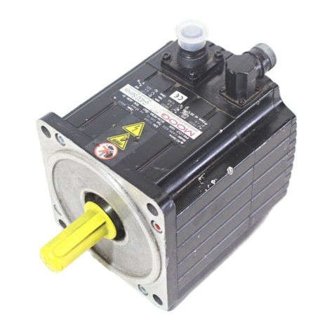
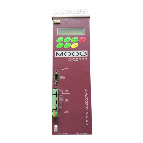
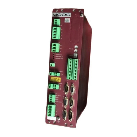
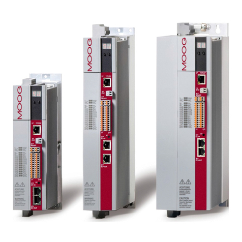
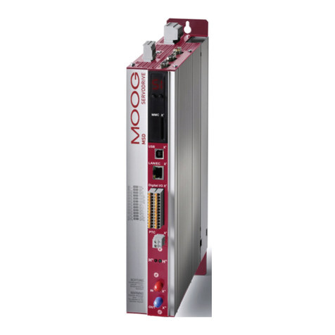
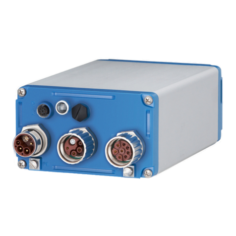
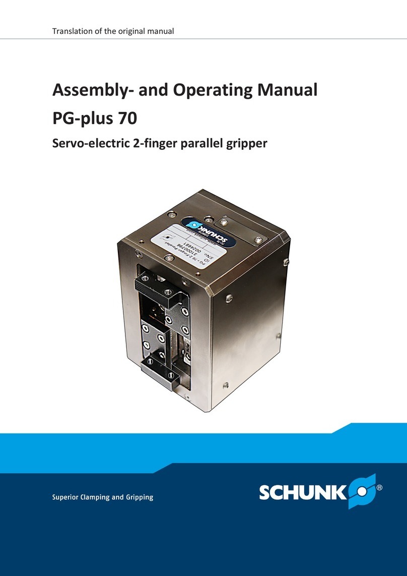
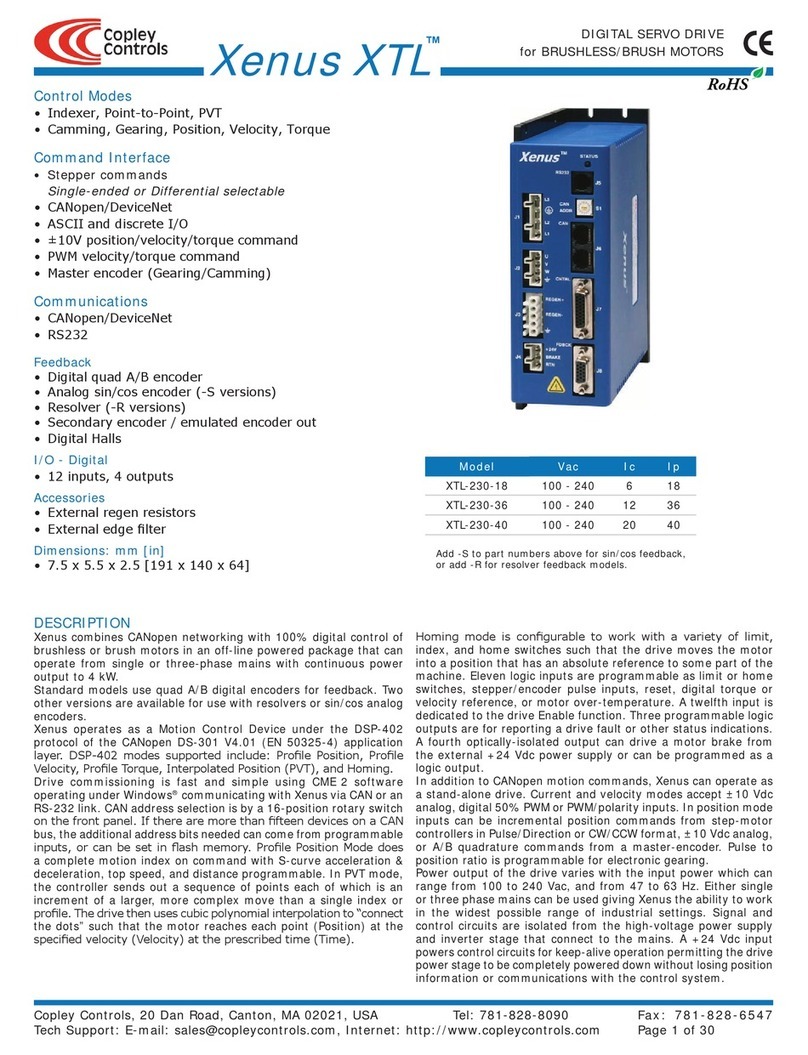
Moog MSD User manual

moog
MSD Servo Drive
User Manual

moog MSD Servo Drive User Manual SERCOS II
User Manual: SERCOS II for MSD Servo Drive
ID no.: CA65648-001, Rev.1.0
Dat e: 11/ 2011
We reserve the right to make technical changes.
Technical alterations reserved.
The contents of our documentation have been compiled with greatest care and in com-
pliance with our present status of information.
Nevertheless we would like to point out that this document cannot always be updated
parallel to the technical further development of our products.
Information and specifications may be changed at any time. For information on the lat-
est version please refer to drives-support@moog.com.

moog MSD Servo Drive User Manual SERCOS II 3
How to use this document
Dear user
This manual is intended for you as a project engineer, commissioning engineer or
programmer of drive and automation solutions on the SERCOS II fieldbus.
It is assumed that you are already familiar with this fieldbus on the basis of
appropriate training and reading of the relevant literature. We assume your drive is
already in operation. If it is not, you should put it into operation as described in the
MSD Servo Drive Operation Manual.
This manual applies to the MSD Servo Drive position drive system with the
SERCOS II option card.
The basis for implementing SERCOS in the MSD Servo Drive is the document titled
“Specification SERCOS Interface Version 2.4“ issued in February 2005
(for more details visit http://www.sercos.de).
11 Summary description
44 Cyclic data transfer
55 Fault, warning and status messages
66 Operation modes
77 Weighting
88 Drive-controlled homing
99 Touchprobe function
1010 Parameter access via the service channel
33 SERCOS communication phases
22 Commissioning of the SERCOS interface

moog MSD Servo Drive User Manual SERCOS II 4
Pictograms
To provide clear guidance, this Operation Manual uses pictograms. Their meanings are
set out in the following table. The pictograms always have the same meanings, even
where they are placed without text, such as next to a connection diagram.
!ATTENTION! Misoperation may result in damage to the drive or malfunctions.
DANGER FROM ELECTRICAL TENSION! Improper behaviour may
endanger human life.
DANGER FROM ROTATING PARTS! Drive may start up automatically.
NOTE: Useful information

moog MSD Servo Drive User Manual SERCOS II 5
Table of contents
1 Safety...................................................................................... 7
1.1 Measures for your safety.........................................................................................7
1.2 Read the Operation Manual first!............................................................................7
1.3 Introduction to the SERCOS interface......................................................................7
1.4 Key features............................................................................................................8
1.5 Terms ...................................................................................................................9
2 Commissioning of the SERCOS interface..................................11
2.1 Connections and controls – hardware variant 1 ......................................................11
2.2 Connections and controls – hardware variant 2 ......................................................11
2.3 Connection of fibre-optic cables .............................................................................12
2.4 Hardware settings...................................................................................................12
2.4.1 Setting the transmission power of the SERCOS interface .............................12
2.4.2 Setting the drive address via parameter .......................................................12
2.4.3 Transfer rate of SERCOS interface ................................................................12
2.5 Diagnostic LEDs ......................................................................................................13
2.5.1 Use of the distortion LED.............................................................................13
2.5.2 Checking fibre-optic cables .........................................................................13
3 SERCOS communication phases ............................................. 15
3.1 Communication phase 0 .........................................................................................15
3.2 Communication phase 1 .........................................................................................15
3.3 Communication phase 2 .........................................................................................15
3.4 Communication phase 3 .........................................................................................16
3.5 Communication phase 4 .........................................................................................16
4 Parameter interface................................................................ 17
4.1 Profile parameters (S-0-xxxx)..................................................................................17
4.1.1 Manufacturer specific parameters (P-0-xxxx)...............................................17
4.2 Cyclic data transfer..................................................................................................17
4.3 Master control word ...............................................................................................18
4.3.1 Description of bits 13-15..............................................................................19
4.4 Drive status word....................................................................................................20
4.5 Drive state machine ................................................................................................22
4.6 Real-time control bits and real-time status bits........................................................23
4.7 Signal control and status words ..............................................................................24
4.7.1 Signal control word (S-0-0145).....................................................................24
5 Fault, warning and status messages ....................................... 27
5.1 Fault messages........................................................................................................27
5.2 Warning messages..................................................................................................28
5.3 Status messages......................................................................................................28
5.4 Interface faults and diagnostic options....................................................................29
5.4.1 Diagnosis of interface status........................................................................29
5.4.2 Fault counter for telegram failures ...............................................................29
6 Operation modes .................................................................. 31
6.1 Torque control ........................................................................................................33
6.2 Flux Control ............................................................................................................34
6.3 Position control with drive-controlled position profile generation ...........................35
6.4 Position control without tracking error....................................................................37
6.4.1 In-drive generation of pre-control signals ....................................................37
6.5 External generation of pre-control signals...............................................................38

moog MSD Servo Drive User Manual SERCOS II 6
7 Weighting ............................................................................. 39
7.1 Weighting of position data .....................................................................................39
7.1.1 Weighting of translatory position data.........................................................39
7.1.2 Weighting of rotary position data................................................................39
7.1.3 Modulo weighting.......................................................................................41
7.1.4 Position polarity...........................................................................................41
7.2 Weighting of velocity data ......................................................................................42
7.2.1 Weighting of translatory velocity data .........................................................42
7.2.2 Weighting of rotary velocity data.................................................................42
7.2.3 Velocity polarity...........................................................................................43
7.3 Weighting of acceleration data ...............................................................................44
7.3.1 Weighting of translatory acceleration data ..................................................44
7.3.2 Weighting of rotary acceleration data..........................................................44
7.4 Weighting of torque and force data........................................................................45
7.4.1 Percentage weighting of torque and force data...........................................45
7.4.2 Weighting of force data...............................................................................45
7.4.3 Weighting of torque data ............................................................................46
7.4.4 Torque polarity ............................................................................................46
8 Homing ................................................................................. 49
8.1 “Drive-controlled homing” command.....................................................................49
8.2 Setting of SERCOS encoders 1 / 2 ...........................................................................49
8.3 Homing velocity ......................................................................................................49
8.4 Homing acceleration...............................................................................................49
8.5 Homing method .....................................................................................................49
8.6 Reference distance 1/2............................................................................................49
8.7 Reference distance offset 1/2..................................................................................49
8.8 Reference cam, limit switches .................................................................................50
8.8.1 Function selector - digital inputs and outputs..............................................50
9 Touchprobe function ............................................................. 51
10 Parameter access via the service channel ................................ 55
10.1 SERCOS parameter list ............................................................................................55

moog MSD Servo Drive User Manual SERCOS II 7
[ Chapter 1 ]
1 Safety
1.1 Measures for your safety
The instructions set out below should be read through prior to initial commissioning in
order to prevent injury and/or damage to property. The safety instructions must be fol-
lowed at all times.
1.2 Read the Operation Manual first!
1.
Read the Operation Manual first!
• Follow the safety instructions!
• Refer to the user information!
Electric drives are dangerous:
• Electrical voltages 230 V to 480 V
Dangerously high voltages of ≥50 V (capacitor charge) may still be
present even 10 minutes after the power is cut. so always make sure the
system is no longer live!
• Rotating parts
• Hot surfaces
Protection against magnetic and/or electromagnetic fields during installation and
operation
• Persons fitted with heart pacemakers, metallic implants and hearing aids etc.
must not be allowed access to the following areas:
– Areas where drive systems are installed, repaired and operated.
– Areas where motors are installed, repaired and operated. Motors with perma-
nent magnets pose a particular hazard.
DANGER: If it is necessary to access such areas, suitability to do so must be
determined beforehand by a doctor.
Your qualification:
• In order to prevent personal injury or damage to property, only personnel with
electrical engineering qualifications may work on the device.
• The said qualified personnel must be familiar with the contents of the Operation
Manual (cf. IEC364, DIN VDE0100).
• Knowledge of national accident prevention regulations (e.g. BGV A3, formerly
VBG 4, in Germany)
U
V
N
L+
RB
L-
L3
L2
L1
U
V
N
L+
RB
L-
L3
L2
L1
During installation observe the following instructions:
• Always comply with the connection conditions and technical specifications.
• Comply with electrical installation standards, e.g. cable cross-section,
PE-conductor and earth connection.
• Do not touch electronic components and contacts (electrostatic discharge may
destroy components).
Table 1.1 Safety instructions
1.3 Introduction to the SERCOS interface
SERCOS stands for SErial Realtime COmmunication System, and is a globally standard-
ized (IEC 61491 and EN61491) digital interface for communication between master con-
trol systems, drive units and other distributed peripherals. The real time-critical transfer
of setpoints and actual values enables numerically controlled high-performance drive
applications to be implemented in the engineering industry.
Services are also provided for operation mode recording, parameter setting, configura-
tion and diagnosis.

moog MSD Servo Drive User Manual SERCOS II 8
Figure 1.1 SERCOS communication module for MSD Servo Drive
The SERCOS communication module for the MSD Servo Drive is implemented as a SERCOS II
interface with a plastic optical fibre (POF) or hard clad silica (HCS) cable loop with F-SMA
connectors. There are currently two hardware variants, though in future only the variant de-
tailed under 2.2 will be manufactured. The hardware and software have, as far as possible,
been developed in conformance to DIN/EN 61491. The basis for implementing SERCOS II is
the document titled Specification SERCOS Interface (Rev. 2.4 issued Feb. 2005).
The power supply to the communication module is provided by the MSD Servo Drive.
Baud rates of 2, 4, 8 and 16 Mbit/s are possible, and are detected automatically by the
module. This means there is no need to preset the baud rate.
Real-time capability permits highly dynamic drive engineering applications with NC cycle
times of 125 µs to 65 ms (multiples of 125 µs). The data to be transferred is defined in
the SERCOS driver in numerous preference telegrams and parameters. They are specially
tailored to the high demands of electric drive systems. A freely configurable telegram
permits optimum utilization of all the possibilities offered by the line based on additional
setpoint and actual value parameters such as increasing the transferred position resolu-
tion, use of the inputs and outputs in the drive in the NC cycle, and much more.
1.4 Key features
•Data transfer via plastic optical fibre (POF) or hard clad silica (HCS) cable with
F-SMA connectors
•Transfer rate: Optionally 2, 4, 8 or 16 MBaud
•Automatic baud rate detection
•Transmission power programmable via DIP switches (hardware variant 1 only),
otherwise via parameters.
Setup using pushbuttons and display in preparation
•Programmable SERCOS address via parameters.
Setup using pushbuttons and display in preparation
•Cyclic data exchange of setpoints and actual values with exact time equidistance
•SERCOS-cycle time of 125 µs to 65 ms (multiples of 125 µs programmable)
•Multi-axis synchronization between setpoint action times and actual value mea-
surement times of all drives in the loop
•Full synchronization of all connected drives with the master control system
•Free configuration of telegram content
•Maximum configurable data volume in MDT: 20 bytes
•Maximum configurable data volume in DT: 20 bytes
•Programmable parameter weighting and polarity for position, velocity, acceleration
and torque
•Additive velocity and torque setpoints
•Fine-interpolation (linear or cubic) inside the drive
•Optionally master control-side (external) or in-drive generation of rotation speed
and acceleration pre-control
•Service channel for parameter setting and diagnosis
•Support for touchprobes 1 and 2
•Support for spindle commands
•Support for configurable real-time status and control bits
•Support for configurable signal status and control word

moog MSD Servo Drive User Manual SERCOS II 9
[ Chapter 1 ]
•Supported commands:
–S-0-0099 Reset state class 1
–S-0-0127 Prepare switch to phase 3
–S-0-0128 Prepare switch to phase 4
–S-0-0148 Drive-controlled homing
–S-0-0152 “Position spindle” command
–S-0-0170 “Touchprobe” command
–S-0-0262 “Parameter initialization to defaults“ command
–S-0-0263 “Parameter initialization to backup values“ command
–S-0-0264 „Save current parameter values” command
1.5 Terms
Term Explanation
SERCOS Standardized method of real-time communication between master control
systems and drives to DIN/EN 61491
OF Optical fibre
MST Master Sync Telegram. Provides ìs-precise data synchronization of the drives in
the fibre-optic loop by the time-slot method
MDT Master Data Telegram. Data from master to the drives in the fibre-optic loop
(control word, setpoints)
DT Drive Telegram. Data from drive to master (status, actual values)
Phase 0..4 SERCOS communication phases
0 = Fibre-optic loop closed by master (reception from MST) )
1 = Master identifies all slaves/drives in the loop
2 = Parameter-setting mode; as from phase 2 the service channel is in operation
3 = Time slots are maintained, cyclic data still invalid
4 = Cyclic operation mode; import of setpoints; transmission of actual values
Table 1.2 Terms
Term Explanation
Cyclic data Time-synchronized transfer of MDT, DT as from phase 3, valid as from phase 4
Service channel Subsidiary protocol in the telegrams.
Parameter values, attributes, scaling and names can be sequentially transferred.
Transfers can also be effected in parallel with the time-critical cyclic data
(MDT, DT) in phases 3 and 4.
The service channel provides services for operation mode recording, param-
eter setting, configuration and diagnosis
IDN Ident Number. S-x-yyyy or P-x-yyyy. 16 bits are available to represent
a SERCOS ident number.
Structure of IDN
15 14 13 12 11 10 9 8 7 6 5 4 3 2 1 0
S/P = 0/1 x = 0..7 yyy = 0..4095
S = SERCOS profile specific parameter (bit 15 = 0) )
P = SERCOS manufacturer specific parameter (bit 15 = 1)
x = Record number 0..7 (bits 14:12)
yyy = Data block number 0..4095 (bits 11:0)
Note: Only record 0 is supported in the drive.
Table 1.2 Terms

moog MSD Servo Drive User Manual SERCOS II 10

moog MSD Servo Drive User Manual SERCOS II 11
[Chapter 2 ]
2 Commissioning of the SERCOS
interface
2.1 Connections and controls – hardware variant 1
The connections and controls of the SERCOS interface hardware variant 1 are shown
schematically in figure 1. LEDs H4 and H5 are status indicators. H4 signals a distortion
(distortion LED), meaning the fibre-optic power is defective or there is a break in the
loop. H5 indicates the current communication phase (0..4). H6 and H7 signal RX/TX
communication. The fibre-optic cables are connected to connectors X17 (transmitter)
and X18 (receiver). The drive address is programmed by way of the corresponding pa-
rameter using the service tool.
Drive address programming using pushbuttons and a display is in preparation.
Figure 2.1
H4
H5
H6 H7
X17 (TXD)
X18 (RXD)
Controls and displays of the SERCOS interface, hardware variant 1
2.2 Connections and controls – hardware variant 2
The connections and controls of the SERCOS interface hardware variant 2 are shown
schematically in figure 2. LEDs H4 and H5 are status indicators. H4 signals a distortion
(distortion LED), meaning the fibre-optic power is defective or there is a break in the
loop. H5 indicates the current communication phase (0..4). The fibre-optic cables are
connected to connectors X30 (transmitter) and X31 (receiver). In hardware variant 2 the
connectors are of an angled design, to reduce the overall depth of the drive. The drive
address is programmed by way of the corresponding parameters using the service tool.
Drive address programming using pushbuttons and a display is in preparation.
Figure 2.2
H4 H5
X30 (TXD)
X31 (RXD)
Controls and displays of the SERCOS interface, hardware variant 2

moog MSD Servo Drive User Manual SERCOS II 12
2.3 Connection of fibre-optic cables
The connection between the master (control) and the servo drives is made by fibre-optic
cables. This requires a loop architecture to be constructed, as illustrated in the following
diagram for three drive axes.
Figure 2.3
24
23
22
21
20
19
18
17
16
15
14
13
12
11
10
9
8
7
6
5
4
3
2
1
REL
REL
ISDSH
ISD06
ISD05
ISD04
ISD03
ISD02
ISD01
ISD00
+24V
DGND
RSH
RSH
ENPO
OSD02
OSD01
OSD00
ISA1-
ISA1+
ISA0-
ISA0+
+24V
DGND
ACHTUNG
WARNING
Kondensatorenent-
ladezeit> 3 min.
Betriebsanleitung
beachten!
Capacitordischarge
time> 3 min.
Payattention to the
operationmanual!
56
X
3
X
1
X
2
X
4
X5
12345678
X
S
X
30
X
31
24
23
22
21
20
19
18
17
16
15
14
13
12
11
10
9
8
7
6
5
4
3
2
1
REL
REL
ISDSH
ISD06
ISD05
ISD04
ISD03
ISD02
ISD01
ISD00
+24V
DGND
RSH
RSH
ENPO
OSD02
OSD01
OSD00
ISA1-
ISA1+
ISA0-
ISA0+
+24V
DGND
ACHTUNG
WARNING
Kondensatorenent-
ladezeit> 3 min.
Betriebsanleitung
beachten!
Capacitordischarge
time> 3 min.
Payattention to the
operationmanual!
56
X3
X1
X2
X4
X5
12345678
X
S4
X
30
X
31
24
23
22
21
20
19
18
17
16
15
14
13
12
11
10
9
8
7
6
5
4
3
2
1
REL
REL
ISDSH
ISD06
ISD05
ISD04
ISD03
ISD02
ISD01
ISD00
+24V
DGND
RSH
RSH
ENPO
OSD02
OSD01
OSD00
ISA1-
ISA1+
ISA0-
ISA0+
+24V
DGND
ACHTUNG
WARNING
Kondensatorenent-
ladezeit> 3 min.
Betriebsanleitung
beachten!
Capacitordischarge
time> 3 min.
Payattention to the
operationmanual!
56
X
3
X
1
X
2
X4
X5
12345678
X
S
X
30
X
31
SERCOS
Master
Connection of fibre-optic cables
The fibre-optic loop starts and ends at the SERCOS master (control). The optical output
of the master is connected to the optical input of the first drive (X31). Its optical output
(X30) is connected to the input of the next drive, and so on. The output of the last drive
is connected to the optical input of the master. The SERCOS slave addresses are assigned
independently of their positions in the loop.
2.4 Hardware settings
2.4.1 Setting the transmission power of the SERCOS interface
By way of parameter P-0-3004 the transmission power of the fibre-optic transmitter can
be set. Entering a 0 corresponds to the lowest power and a 3 the highest. The following
values are intended as a guide:
0: <15 m
1: 15 .. 30 m
2: 30 .. 45 m
3: >45 or HCS
0: <15 m 1: 15 .. 30 m 2: 30..45 m 3: >45 or HCS
2.4.2 Setting the drive address via parameter
The drive address is set in parameter P-0-3000 (Drive address). EA drive address setting
or change made in this parameter only takes effect the next time the communication
phase changes from “0” to “1”. The drive address is independent of the position of the
drive in the SERCOS loop.
Drive address programming using pushbuttons and a display is in preparation.
2.4.3 Transfer rate of SERCOS interface
The transfer rate specified by the master is automatically detected by the drive, set ac-
cordingly and indicated in parameter S-0-0376: Baud rate, SERCOS interface.
NOTE: Baud rates of 2, 4, 8 and 16 MBaud are supported. Automatic baud
rate detection in the drive is implemented according to SERCOS Application
Note AN15 dated 2002/08/22.

moog MSD Servo Drive User Manual SERCOS II 13
[Chapter 2 ]
2.5 Diagnostic LEDs
Hardware variant 1
LED Colour Meaning
H5
H4
H6 H7
H5
H4
H6 H7
H4 Red Distortion LED, fault on bus
H5 Green Status of SERCOS communication phase (flash code)
H6 Green Receiver LED, telegrams being received
H7 Green Transmitter LED, telegrams being sent
Hardware variant 2
LED Colour Meaning
H5
H4
H6 H7
H5
H4
H6 H7
H4 Red Distortion LED, fault on bus
H5 Green Status of SERCOS communication phase (flash code)
2.5.1 Use of the distortion LED
When you have set the drive address, you should check that there is an adequate optical
signal level at each station in the loop - that is, that the receiver is not being underload-
ed or overloaded. The optical level is checked by way of the distortion LED on the front
panel of the MSD Servo Drive (LED H4). Normally the distortion LED is unlit. To check
the optical level, check the distortion LEDs of all the drives in the loop, starting from the
transmitter output of the master, in the direction of the signal flow (see diagram under
“Connection of fibre-optic cables”). Check the distortion LEDs in the direction of the
light signal flow - that is, starting with the first drive in the loop. If its distortion LED is
unlit, move on to the next drive. Continue doing this until you reach the last drive, and
then the master (control).
NOTE: The distortion LED must not be lit or flashing.
A distortion LED lights up in the following cases:
•Defective fibre-optic cable to predecessor
•Unsupported transfer rate
•Incorrectly set transmission power
Procedure if distortion LED is lit:
Check the fibre-optic cable, with its connectors, from its physical predecessor in the
loop to the affected drive (see below). Compare the transfer rate of the master with the
supported drive baud rates. On the physical predecessor of the affected drive, check the
transmission power setting and adjust it as necessary by the DIP switches (HW variant 1)
or via parameter P-0-3004 (HW variant 2). In HW variant 1 parameter P-0-3004 only has
an influence if a higher transmission power is set on the DIP switches. That is to say, the
lowest transmission power set via the parameter or the DIP switches determines the actual
effective transmission power. It is not possible to upscale by way of the other channel.
2.5.2 Checking fibre-optic cables
If the specified transfer rate is supported and the transmission power is correctly set, but
still no communication takes place, the fibre-optic cable may be defective. In this case
the distortion LED will light. The cause of a defect in a fibre-optic cable may be mechani-
cal damage or poor assembly (bad connector fitting or the like). Defective fibre-optic
cables must be replaced.
NOTE: Fibre-optic transmission is sensitive to dirt contamination. Make sure
no dirt particles can penetrate the transmitter or receiver elements. This may
lead to transmission power and distortion problems which are difficult to
localize. Protect the elements during installation using the supplied sheaths
until the fibre-optic cables have been assembled.

moog MSD Servo Drive User Manual SERCOS II 14

moog MSD Servo Drive User Manual SERCOS II 15
[Chapter 3 ]
3 SERCOS communication
phases
Communication over the SERCOS bus between the master and slaves is divided into
five phases. Communication phases 0 and 1 identify the stations on the bus. In com-
munication phase 2 the time and data structure of the protocols for phases 3 and 4 are
prepared and the drive is configured. At the transition to communication phase 3 the
drive parameter settings relating to the SERCOS profile are checked for plausibility. In the
event of a fault, the switch to communication phase 3 is refused with a relevant fault
message. The phases are run through in ascending order. It is only possible to drop back
a phase by way of communication phase 0. The communication phase is dictated by
the master. On switching to communication phase 4, the initialization is completed and
power-up is enabled.If the phase sequence is interrupted, the status indicator remains
stuck at the last communication phase reached. The current communication phase is
indicated by way of a flash code by LED H5. Intervals of about one second unlit are
followed by LED H5 flashing briefly “n” times, “n” being the number of the current com-
munication phase.
3.1 Communication phase 0
When communication phase 0 is active, automatic baud rate detection in the drive has
completed successfully. The drive is in communication phase 0 and is waiting for the
master to switch from phase “0” to “1”. During communication phase 0 the green LED
H5 on the drive unit remains unlit.
LED H5 flash code Status
▂▂▂▂▂▂▂▂▂
H5H4
H5H4 Indication of communication phase 0
Table 3.1 Flash code: Communication phase 0
3.2 Communication phase 1
If communication phase 1 is active, the drive is in phase 1. The master has not yet trig-
gered a switch from phase “1” to “2”. During communication phase 1 the green LED H5
on the drive unit cyclically displays the flash code set out in the following table.
LED H5 flash code Status
█▂▂▂█▂▂▂ H5H4
H5H4
Indication of communication phase 1
Table 3.2 Flash code: Communication phase 1
3.3 Communication phase 2
Communication phase 2 signifies that the drive is in parameter-setting mode. IIn this
mode you can write to many parameters which are no longer editable in communica-
tion phase 4 (operation mode). In communication phase 2 the communication param-
eters are usually transferred from the master to the drive. All parameters influencing
the switching frequency or the sampling times of the loop control system can likewise
be written only in communication phase 2. During communication phase 2 the green
LED H5 on the drive unit cyclically displays the flash code set out in the following table.
To enter communication phase 2, the master specifies “Communication phase 2” in the
Master Sync Telegram.
Before the system can switch to communication phase 3, command S-0-0127 - Prepare
switch to communication phase 3 - must be executed. During this preparatory phase the
drive checks criteria including the validity of the parameters required for communica-
tion phase 3. When the prepare-to-switch command has been successfully executed,
the drive is switched to communication phase 3 by the master. In the event of a fault
(plausibility of the setting concerned), the switch to communication phase 3 is refused
with a relevant fault message.
NOTE: On switching to phase 3, the servo drive performs all the necessary ini-
tializations. If it is not possible to switch to phase 3 because of faulty parameter
setting, the drive generates a relevant fault message. The meanings of the fault
numbers are listed in the MSD Servo Drive Application Manual.

moog MSD Servo Drive User Manual SERCOS II 16
The parameter listing in section 10.1 sets out the parameters that can be
written in the various phases.
LED H5 flash code Status
█▂█▂▂▂█▂█▂▂▂ H5H4
H5H4
Indication of communication phase 2
Table 3.3 Flash code: Communication phase 2
3.4 Communication phase 3
Communication phase 3 signifies that the drive is in restricted parameter-setting mode.
In this mode - as in parameter-setting mode (phase 2) - you can write to many param-
eters which are no longer editable in communication phase 4 (operation mode). No
communication parameters can be written in phase 3. During communication phase 3
the green LED H5 on the drive unit cyclically displays the flash code set out in the follow-
ing table.
LED H5 flash code Status
█▂█▂█▂▂▂█▂█▂█▂▂▂ H5H4
H5H4
Indication of communication
phase 3
Table 3.4 Flash code: Communication phase 3
3.5 Communication phase 4
Before the system can switch to communication phase 4, command S-0-0128 - “Prepare
switch to communication phase 4” - must be executed. During this preparatory phase
the drive checks criteria including the validity of the parameters required for communica-
tion phase 4. When the prepare-to-switch command has been successfully executed,
the drive is switched to communication phase 4 by the master. During communication
phase 4 the green LED H5 on the drive unit cyclically displays the flash code set out in
the following table. The drive can only be enabled via the control word in communica-
tion phase 4.
LED H5 flash code Status
█▂█▂█▂█▂▂▂█▂█▂█▂█▂▂▂ H5H4
H5H4
Indication of commu-
nication phase 4
Table 3.5 Flash code: Communication phase 4

moog MSD Servo Drive User Manual SERCOS II 17
[Chapter 4 ]
4 Parameter interface
4.1 Profile parameters (S-0-xxxx)
The SERCOS specific profile parameters (S-0-0001 .. S-0-4095) are mapped as Moog
parameters (P-0-10001 ... to P-0-14095). The corresponding addressing is:
Moog ID - 10000 dec
4.1.1 Manufacturer specific parameters (P-0-xxxx)
The manufacturer specific parameters (Moog parameters) (P-0-0001 .. P-0-4095) are ad-
dressed as follows as P-parameters:
Moog ID + 8000 hex
Example: Moog P-0-0101 function selector ISD01 is to be found in the IDN listing
(S-0-0017) as P-0-0101.
Currently only record 0 is supported.
SERCOS currently does not support language switching. English is installed by default.
4.2 Cyclic data transfer
To synchronize the drives in the loop, at the start of each SERCOS cycle (cycle time
tScyc = S-0-0002) the master sync telegram (MST) is sent (see diagram below). Its only
information content is the communication phase dictated by the master. The contents of
the master data telegram (MDT) and the drive telegram (DT) are configurable. The con-
trol sends a common master data telegram for all drives to the drives once per SERCOS
cycle. It contains the master control word, the service channel (parameter channel) and a
configurable data block. This data block usually contains setpoints and limit values which
the master control system wants to send to the drive to run the desired operation mode.
The content of this data block can be configured by the telegram setting. The master
data telegram is received simultaneously by all the drives in the loop. Likewise once per
SERCOS cycle, each drive sends a separate drive telegram to the master control. It con-
tains the drive status word, extracts from the service channel and a configurable data
block. This data block usually contains actual and status values which the master control
system needs to run the desired operation mode.
Figure 4.1
AT
A
T AT MDT
t
m
2
1
1.1
t
1.2
t
1.M
t
2
t
Scyc
A
T
M
t
1.m
AT
A
T AT MDT
t
m
2
1.1
t
1.2
t
1.M
t
2
t
Scyc
A
T
M
t
1.m
MSTMST
SERCOS cycle timing diagram

moog MSD Servo Drive User Manual SERCOS II 18
4.3 Master control word
The master control word is part of the master data telegram. It contains all the key con-
trol information for the drive.
The master control word is mapped in parameter S-0-0134. The precise structure of
this parameter is shown in the following table. The master control word is transferred
cyclically to the drive with each master data telegram in the SERCOS cycle (see “SERCOS
cycle time”). For diagnostic purposes, the master control word can be read via param-
eter S-0-0134, “Master control word”.
Bit Explanation
Bits 15-13
1 1 1 Drive to follow setpoints
Bit 15 (MSB) Drive ON/OFF
0DriveOFF:Onswitchingfrom1•0thedriveisshutdownasbestaspossible
(according to the setting of P-0-2219), then the torque is shut off as necessary
at standstill; the power stage can remain active (only possible if bit 14 = 1 and
with corresponding setting of P-0-2219), then the torque is shut off at speed
nmin; the power stage can remain active (only possible if bit 14 = 1)
1 Drive ON
Bit 14 Drive ENABLE
0Noenable.Onswitching1•0thetorqueisshutoffandthepowerstage
disabled with no delay (regardless of bits 15 and 13)
1Drive enable
Bit 13 Drive HALT (can be used to stop the drive without reference to the current
active control function)
0 Drive stop: The drive is no longer following the setpoints. On switching from
1•0thedrivestopsaccordingtothesettingofP-0-2221 and taking into
account the last active acceleration (by default according to acceleration
parameter P-0-2242) and remains under control (only possible if bits 14 and 15
= 1 and with an appropriate setting of P-0-2221)
1Drivestart:Onswitchingfrom0•1theoriginalfunctionisresumed.Ifthe
master control system has not updated the position, setpoint jumps may oc-
cur, resulting in shut-off due to tracking error.
Bit 12 Reserved
Bit 10 IPOSYNC: Not supported
Bit 11, 9, 8 Specified operation mode
Table 4.1 Master control word (parameter S-0-0134)
Bit Explanation
0 0 0 Primary mode (defined by operation datum S-0-0032)
0 0 1 Secondary mode-1 (defined by operation datum S-0-0033)
0 1 0 Secondary mode-2 (defined by operation datum S-0-0034)
0 1 1 Secondary mode-3 (defined by operation datum S-0-0035)
Bit 7 Real-time control bit 2 (S-0-0302)
Bit 6 Real-time control bit 1 (S-0-0300)
Bit 5, 4, 3 Data block element
0 0 0 Service channel not activated, close the service channel or abort an ongoing
transfer.
0 0 1 IDN of operation datum. The service channel is closed for the preceding IDN
and opened for a new one.
0 1 0 Name of operation datum
0 1 1 Attribute of operation datum
1 0 0 Units of operation datum
1 0 1 Minimum input value
1 1 0 Maximum input value
1 1 1 Operation datum
Bit 2
0Ongoing transfer
1Last transfer
Bit 1 R/W (Read/Write)
0 Read service INFO
1 Write service INFO
Bit 0 „MHS“
0/1 Service transport handshake of master
Table 4.1 Master control word (parameter S-0-0134)

moog MSD Servo Drive User Manual SERCOS II 19
[Chapter 4 ]
4.3.1 Description of bits 13-15
Bit14: Drive ENABLE (power stage enable)
The MSD Servo Drive has a control input (X4.10) ENPO (Enable Power) for hardware en-
able. This input must be configured for operation of the power stage at 24 V.
The device additionally features the “STO” (Safe Torque Off) function, category 3 (see
MSD Servo Drive Operation Manual and Application Manual) via control input (X4.22)
ISDSH. The logic for this function (High edge at digital input ENPO (X4.10), with a High
signal required at the digital input ISDSH (X4.22) at the time the edge occurs) must be
fulfilled by the higher-level control system according to Application Manual.
NOTE: If the ENPO and ISDSH inputs are not configured, the device remains in
state 1 = “Not Ready to Switch On” or 2 = “Switch On Disabled”. In the STO
state the status indicator flashes “S1” or “S2” as appropriate.
Only after correct configuration of ENPO (X4.10) and ISDSH (X4.22) can the hardware
be enabled by bit 14 in the SERCOS control word MDT (Master Data Telegram). It is only
possible to enable the drive via bit 14 in communication phase 4.
Bit 15: Control ON/OFF (drive enable)
Control of the drive via the SERCOS interface requires just a few parameter settings:
•Open-loop control setting of drive via SERCOS interface: Set P-0-0159 to SERCOS
(6).
•Setpoints via SERCOS profile: Set P-0-0165 to SERCOS (8)
•Evaluation of bit 15 in MDT state-controlled (1 = LEVEL) or edge-controlled (0 =
EDGE) via P-0-0144.
Note:
If bit 14 and bit 15 in the MDT are set simultaneously, P-0-0144 must be set to
LEVEL (1).
In summary: For the drive enable signal (bit 15) to be accepted - that is, for the drive to
switch from the unpowered to the powered state - the following conditions must be
met:
•SERCOS interface ready and in communication phase 4
•Enable power pack via hardware (ENPO and ISDSH) and bit 14 in MDT
•Drive not in fault state
•Settings of relevant parameters P-0-0144, P-0-0159 and P-0-0165
Under these preconditions the drive shows device state “3” on the display. The drive is
activated by the change of state from 0 to 1 of bit 15 (drive enable) in the MDT. If the
enable is successfully executed, the display readout changes to 5 and the relevant bits in
the drive telegram (DT) are operated.
The readiness of the control (drive follows setpoints) is mapped in the status word via bit
15, bit 14 and bit 3.
Ideally, the master control system reads the actual value while control is starting and
presets it as the setpoint until the closed-loop drive signals readiness in the status word.
If the drive moves while control is starting (such as due to motor commutation finding by
linear drives, whereby the drive does not yet signal readiness - drive state 4), the position
changes are automatically adopted by the master control system.
Control systems which retrieve the current actual position “only once“ prior to start of
closed-loop control and preset it as the setpoint, and also do not update it even after
commutation finding (no evaluation of status word) will feed forward a setpoint differ-
ence. Shut-off due to tracking error may be the consequence.
To avoid this, the drive can be moved to the position specified by the master control
system at start of control under drive control with parameter P-0-0156 (Enable operation
option code) set to MOVE_COMMAND(1). This aims to exclude the possibility of a shut-
off or a jerky approach to the target position at start of control because of a setpoint
difference in the axis.
This function also depends on the configuration of P-0-0743 (maximum tracking error).

moog MSD Servo Drive User Manual SERCOS II 20
•P-0-0743 equal to 0
Position tracking error off. The drive switches on without correction and feeds
the position setpoint of the NC directly onto the drive. The drive moves to the
target position with a jerk as necessary. Major differences end in a speed tracking
error, depending on the parameter setting. A jerky axis motion is the consequence.
•P-0-0743 not equal to 0
Position tracking error on. The drive reads the target position of the master con-
trol system and moves under drive control to that position (position correction).
If the difference between the position specified by the control system and the
actual position is greater than the tracking error (P-0-0743), the drive switches to a
fault state, now without moving (no major axis motion). Otherwise the drive cor-
rects the difference with the slow jog rate (P-0-0168[1]) and the acceleration from
P-0-2242 (quick-stop). When the position has been reached, the drive switches to
state 5 and the drive follows the setpoints of the master control system (only now
is readiness signalled in the control word).
IMPORTANT:
With the scaling, the ramp setting which the system accesses must also be set correctly
and to reasonable values. This involves the parameters:
•P-0-2242 (Quick-stop). This is applied in the event of a fault, depending on the
configuration
•P-0-0168 (Jog, index 0: Jog rate rapid, index 1: Jog rate slow)
The position correction described above may take a very long time at a very slow jog
rate, or may even not take place at all, such as if P-0-0168[1] = 0. In this case the drive
would remain in system state 4, as the setpoint cannot be attained.
Bit 13: Drive HALT (feed hold)
The “Drive halt“ signal is state-controlled and low-active, meaning in response to a
“Drive halt = 0“ signal the drive is in the “Drive halt” state. The input signal is mapped
in the master control word, bit 13.
4.4 Drive status word
The drive status word is part of the drive telegram. It contains all the key status informa-
tion of the drive, e.g.:
•Readiness of control and power pack
•Drive fault
•Change bits state class 2 and 3
•Current mode
•Real-time status bits 1 and 2
•Status information for service channel
The drive status word is mapped in parameter S-0-0135. The precise structure of this
parameter is shown in the following table. The drive status word is transferred cyclically
to the control system with each drive telegram in the SERCOS cycle (see S-0-0002,
“SERCOS cycle time (TScyc)”). For diagnostic purposes, the drive status word can be
read via parameter S-0-0135, “Drive status word”.
Bit Explanation
Bits 15, 14 „Ready“
0 0 Drive not ready to power up, as internal checks have not yet completed suc-
cessfully.
0 1 Drive ready to power up.
1 0 Drive control unit ready and power supply on, drive is torque-free and power
stage is disabled.
1 0 Drive control unit ready and power supply on, drive is torque-free and power
stage is disabled.
1 1 Drive ready, “Drive enable“ set and effective, power stage active.
Bit 13 Drive lockout fault in C1D (operation datum S-0-0011)
0No fault
1 Drive locked due to a fault situation
Bit 12 Change bit of C2D (operation datum S-0-0012)
0No change
1Change
Table 4.2 Drive status word (parameter S-0-0135)
Other manuals for MSD
3
Table of contents
Other Moog Servo Drive manuals
Popular Servo Drive manuals by other brands
Glentek
Glentek SMB9675-1A-1-7700 Installation & operation manual
Rockwell Automation
Rockwell Automation Allen-Bradley Kinetix TLP Series installation instructions
Siemens
Siemens SINAMICS S210 operating instructions
Moons'
Moons' SSDC-4X-ECX Hardware manual
Danfoss
Danfoss VLT AutomationDrive FC 302 operating guide

Robotis
Robotis XH430-W350-T manual
