meibes Rossweiner Logosonic User manual

Meibes System-Technik GmbH
Ringstraße 18 · D-04827 Gerichshain · Tel. + 49(0) 3 42 92 7 13-0 · Fax 7 13-808
Internet: www.meibes.de · E-Mail: info@meibes.de
Einbauanleitung
PR 5394690 22-08-2018 Technische Änderungen vorbehalten
logosonic - Ultraschall-Energiezähler DE
logosonic - Ultrasonic energy meter
Installation Guide GB
logosonic - Compteur d'énergie à ultrasons
Instructions d’installation FR
logosonic - Contador de energía por ultrasonido
Contador de energia de ultrasonidos ES
Diese Anleitung
ist dem Endkunden
auszuhändigen.
This guide must be given
to the end consumer.
Ce guide doit être donnée
au client final.
Esta guía se debe dar al
cliente final.

18
Content
1. General 19
2. Transportation and storage 20
3. Installing the energy meter 21
4. Temperature sensors 24
4.1 Installation in a ball valve with adapter 24
4.2 Installing in an immersion sleeve 25
5. Commissioning 26
5.1 Flow/return line setting (optional in factory) 26
6. Communication 28
6.1 Wireless communication 28
6.2 M-Bus communication module 28
7. Display 29
8. Operation 31
9. Error code display 32
10. Environmental Notice &
Declaration of Conformity 33

19
1. General
These instructions are intended for authorised specialist personnel. Basic work steps are therefore not included.
The seal of the energy meter must not be damaged! A damaged seal will automatically invalidate the
factory warranty and will require calibration of the meter. The supplied cables must not be shortened or
lengthened or modified in any other way.
Statutory requirements and operating regulations for the use of energy meters must be observed.
Installation may only be performed by an electrical company that specialises in energy meter installation.
Personnel must be trained in the installation and handling of energy meters and electrical devices, as well as the
applicable guidelines.
Medium: water, according to CEN/TR 16911.
When using water additives (e.g. corrosion protection), the user must ensure adequate corrosion resistance.
• The media temperature is specified as 5 ... 105°C (130°C)
• The temperature range depends on variants and nominal sizes.
• The exact temperature range is stated on the type plate.
• In the case of condensation, the sealed version should be selected.
• The operating/environmental conditions are specified as 5-55°C; IP 54/65; 93% rel. humidity.
• Ambient temperatures below 35°C are favourable of the service life of the battery.
If the flow sensor is insulated with the pipework, the counter must be exposed.
Reading and parameterisation is performed by the software program IZAR@MOBILE 2.
GB

20
2. Transportation and storage
Unpacking
Energy meters are measurement devices and must be handled with care. To protect them against damage and dirt,
they must only be removed from the packaging immediately prior to installation.
Transporting
The meter may only be transported in the original packaging.
When sending wireless measurement devices/components by air freight, the wireless function must be
deactivated prior to dispatch.
21
3. Installing the energy meter
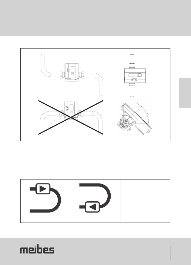
Fig. 1
• Depending on its design and application (heat meter, cold meter), the energy meter is either installed in the hot
branch or the cold branch of the system.
• The flow sensor must be installed so that the direction of flow matches the direction of the arrow on the sensor.
• Depending on the model, the flow sensor must be installed in the flow line or the return line. The installation
position is displayed in info loop 3.4 (see “Info loop (3)” on page 30) and also a pictogram.
Flow line Return line
Without pictogram
(Installation position adjustable on
site, see 5.1 page 26)
GB

22
3. Installing the energy meter
• Stabilising sections upstream and downstream from the flow sensor are not required. A straight section
upstream from the flow sensor with 3...10 DN is recommended for slowing down the flow in systems without
temperature mixing.
The meter may be installed in horizontal or vertical pipes, but never in a position that allows air bubbles
to collect inside. The flow sensor must always be filled with liquid. Frost must be prevented from occur-
ring inside the meter.
• We recommend installing the flow sensor at an angle by 45°.
• The system pressure must be 1 bar in order to prevent cavitation.
• There must be sufficient distance between the meter and potential sources of electromagnetic interference
(switches, electric motors, fluorescent lamps, etc.).
• The cables of the flow sensor or temperature sensor must hang free (not bundled together, as this has an
antenna effect) and laid at a sufficient distance from electromagnetic interferences.
T: 5-90°C
TWater > TEnvironment
T: 5-105/130°C
TWater < TEnvironment
• The counter must be removed at media temperatures above 90 °C or where TWater< TEnvironment (use of cold
meters or heat meters with cold tariff) and installed at a sufficient distance from heat sources. A wall bracket
(scope of supply) or offset bracket (optional) are available for this purpose.

23
3. Installing the energy meter
Offset bracket
Wall-mounted
installation
• To make it easier to disassemble the energy meter, we recommend installing shut-off valves upstream and
downstream from the energy meter.
• The meter should be installed in a position that is comfortable for service and operating personnel to reach.
• A final commissioning process must be performed and documented.
GB

24
4. Temperature sensors
Handle the temperature sensors with care!
The sensor cables have colour-coded type plates:
• Red: sensor in hot branch
• Blue: sensor in cold branch
• Shortening or lengthening the connection lines is not permissible.
• The free temperature sensors can be installed directly immersed (e.g. ball valve) or in a conformity-tested
immersion sleeve for this type of sensor.
• The sensors must be installed symmetrically.
4.1 Installation in a ball valve with adapter
(Set of threaded joints in separate bag)
Use ball valves that can be installed with a temperature sensor with a thread of M10 x 1.
Preparatory tasks
• Close the ball valve.
• Unscrew the locking screw from the ball valve.

25
4. Temperature sensors
Installation
2
1
4
3
5
A
B
A
B
A
B
Fig. 2
1. Place the O-ring from the enclosed set of threaded joints (Type A or B) onto the mounting pin.
2. Insert the O-ring with the mounting pin into the sensor hole of the ball valve (rotating the mounting pin while
doing so).
3. Move the O-ring into its final position with the other end of the mounting pin.
4. Mounting screw
• Type A (plastic) - place the mounting screw on the temperature sensor.
• Type B (brass) - insert the temperature sensor in the mounting screw and position the sensor in the
mounting pin. Press the grooved pin in all the way and remove the mounting pin.
5. Insert the temperature sensor with mounting screw into the ball valve and tighten by hand (2-3 Nm).
4.2 Installing in an immersion sleeve
In new installations, the temperature sensors for nominal size DN25 or smaller should only be installed directly
immersed. This is to ensure higher temperature measuring accuracy.
GB
26
5. Commissioning
Once the meter has been installed, the components (counter, volume transmitter and both temperature sensors)
must be sealed and the meter must be put into operation by a legally authorised specialist company.
• When doing so, check the display to verify the plausibility of the flow and temperatures.
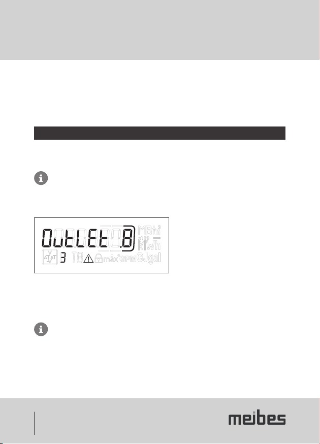
5.1 Flow⁄return line setting (optional in factory)
In loop 3 ("3.4" on page 30) the installation position of the meter can be adjusted on site as required. It is there-
fore possible to install the device in the inlet (flow line) or outlet (return line).
This adjustment must be made prior to commissioning the meter.
The outlet (return line) is preadjusted on delivery and appears in the display as follows.
Setting and number of possible changes.
To make adjustments, switch to loop 3 (see 9. Operation) to the window displaying “Auslauf” (outlet). When
pressing and holding down the key for >6 s, the display/setting changes to “Einlauf” (inlet). This setting can be
changed a total of 8 times by pressing the key.
The display changes during the 6 s.
This does not affect the function.

27
5. Commissioning
Sequence when making changes
Key pressed <3 s Key pressed >3 s
When pressing and holding down the key for a further >6 s, the meter performs the command shown in the
display.
With every change, the framed number in the
display reduces by 1.
After changing 8 times, it is no longer possible to change the installation position.
The ability to make changes either ends immediately with the detection of water or after three hours in
operation without having identified any faults (preadjusted in the factory).
The following appears in the display (example):
Display for making changes disappears.
GB

28
6. Communication
The counter supports two communication channels (wireless or M-Bus).
The protocols can be different for each of the two communication channels and are pre-adjusted in the factory.
6.1 Wireless communication
The integrated wireless function is an interface for communication with wireless receivers.
The unidirectional communication is specified as:
• Send every 8 ... 256 s (variable according to max. 0.1% duty cycle (min. 8 s); depending on the protocol
length and programming)
• The communication always transmits the current measured data
• Transmission frequency: 868 MHz
• Various receivers are available to receive the protocol (e.g. Bluetooth, GPRS, LAN, etc.)
• The protocol is OMS Profile A or Profile B and is encrypted
• Reading technology: Stationary or mobile
6.2 M-Bus communication module
Communication with M-Bus is a serial interface for communication with external devices (M-Bus central controller),
e.g. Rossweiner data collector. Several meters can be connected to one central controller.
• The connection is polarity independent and galvanically separated
• M-Bus protocol in accordance with EN 1434;
• 300 or 2400 Baud (auto Baud detect)
• Connection option: 2 x 2.5 mm²;
• Current consumption: One M-Bus load
29
7. Display
In order for the data generated by the counter to appear in the display, there are various windows containing
designated system information (e.g. energy quantities, water volumes, operating days, water quantities, current
temperatures, maximum values) that can be called up consecutively in loop functions. The energy meter has up to
6 different display loops.
Main loop, due date loop, info loop and month loop.
The month loop consist of up to seven value displays that alternate in a 2-4 s rhythm. For fast visual recognition,
the loops in the display are marked with numbers 1 to 6. The main loop is programmed by default with the current
data, e.g. for energy, volumes, flow rate and the temperatures. The calibrated register is displayed with a padlock
symbol.
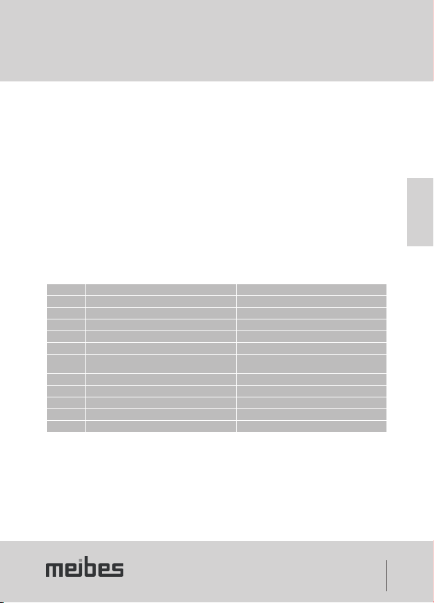
Main loop (1)
Sequence Window 1 Window 2
1.1 Cumulative energy
1.2 Cumulative volume
1.3 Cumulative cold energy (heat meters with a cold tariff)
1.4 Flow
1.5 Power
1.6 Flow line temperature
Return line temperature *)
1.6b High-resolution temperature change display (option) Return line temperature **)
1.7 Differential temperature
1.8 Operating days
1.9 Error status Error hours
1.10 Display test
* Without decimal place ** Each with one decimal place
GB

30
7. Display
Due date loop (2)
Sequence Window 1 Window 2 Window 3
2.1 Due date 1 - date Due date 1 - energy "Accd 1"
2.2 "Accd 1" Future due date 1
2.3 Due date 1 - previous year - date Due date 1 - previous year - energy "Accd 1L"
2.4 Due date 2 - date Due date 2 - energy "Accd 2A"
2.5 "Accd 2" Future due date 2
2.6 Due date 2 - previous year - date Due date 2 - previous year - energy "Accd 2L"
Info loop (3)
Sequence Window 1 Window 2
3.1 Current date
3.2 "SEC_Adr" Secondary address
3.3 "PRI_Adr 1" Primary address
3.4 Installation location
3.5 "UHF ON" (Status of integrated wireless)
3.6 Software version Check sum
Tariff loop (5) 1
Month loop (6)
Sequence Window 1 Window 2 Window 3 Window 4
6.1 "LOG" Date-1 Energy Volume
6.2 "LOG" Date-2 Energy Volume
: : : : :
6.24 "LOG" Date-24 Energy Volume
1Only with heat meters with active cold tari

31
8. Operation
The push-key can be used to page through the individual displays. Short and long key activations have different
functions. A short push of the key (<3 seconds) takes the user to the next display in the loop; a long push of the
key (>3 seconds) takes the user to the next display loop. The "Energy” window (sequence 1.1) of the main loop is
the basic display. If the key is not activated for approx. 4 minutes, the meter automatically switches off the display
to save power (exception: in the event of an error). If the key is pressed again, the meter displays the basic display.
GB

32
9. Error code display
If an error occurs, the error code appears in the main loop. All other windows are still available by pressing the key.
After approx. 4 min without key activation, the error code display will appear again automatically.
The error code disappears automatically as soon as the error has been rectified. All errors that remain for longer
than 6 minutes are saved in the fault memory.
Error code Description
C-1 Basic parameters on flash drive or in RAM corrupted
E 1 Temperature range outside [-19.9 °C...199.9 °C] e.g. sensor short circuited, sensor broken
E 3* Flow line and return line sensor inverted
E 4 Hardware error US measurement, e.g. converter or controller faulty or short circuit
E 5 Communication not possible (too many readings)
E 6* Wrong direction of flow in volumetric flow meter
E 7 Poor ultrasonic reception signal, e.g. air in the measured section
E 9 Battery almost empty, end of calculated service life
* Application-dependent

33
10. Environmental Notice & Declaration of Conformity
Environmental notice
This product must be disposed of separately. Please contact a designated collection point for used batteries or your
Meibes dealer.
Declaration of Conformity for devices in accordance with MID
The Declaration of Conformity is included with the device.
GB

34
Sommaire
1. Généralités 35
2. Transport et stockage 36
3. Montage du compteur d’énergie 37
4. Sonde de température 40
4.1 Montage dans une vanne à boisseau
sphérique avec adaptateur 40
4.2 Montage dans un doigt de gant 41
5. Mise en service 42
5.1 Réglage départ/retour (en option en usine) 42
6. Communication 44
6.1 Communication par radio 44
6.2 Module de communication M-Bus 44
7. Affichage 45
9. Affichage des codes d’erreur 48
10. Remarque sur l’environnement &
déclaration de conformité 49

35
1. Généralités
Ce manuel s'adresse à des techniciens spécialisés et formés. Par conséquent, les étapes de travail de base n’y
sont pas détaillées.
Ne pas détruire le plombage du compteur d'énergie! Une violation du plombage entraîne l’annulation
immédiate de la garantie usine et de l’étalonnage. Les câbles fournis ne doivent être ni raccourcis ni
rallongés ni modifiés d’une quelconque façon.
Respecter les prescriptions légales et les consignes d’utilisation des compteurs d'énergie! Le montage
doit être exécuté uniquement par un professionnel spécialisé dans l’installation des compteurs d'énergie
et en électricité. Le personnel doit être formé à l’installation et à la manipulation des compteurs d'énergie et des
appareils électriques et connaître les directives en vigueur.
Fluide: eau, selon CEN/TR 16911.
En cas d'utilisation d’additifs dans l’eau (p. ex. un produit anticorrosif), l’utilisateur doit s’assurer de la résistance
suffisante à la corrosion.
• La température du fluide est définie à 5 ... 105 °C (130 °C)
• Plage de température en fonction de la version et de la taille nominale.
• La plage de température exacte est indiquée sur la plaque signalétique.
• En présence de condensation, choisir la version moulée.
• Les conditions de fonctionnement/environnementales sont définies à 5 … 55 °C; IP 54/65; humidité rel. de 93 %.
• Des températures environnementales inférieures à 35°C prolongent la durée de vie de la batterie.
Si le capteur de débit est isolé avec la conduite, l’unité de calcul doit être dégagée.
La lecture des données et le paramétrage s’effectuent à l’aide du logiciel IZAR@MOBILE 2.
FR

36
2. Transport et stockage
Déballage
Les compteurs d'énergie sont des instruments de mesure et doivent être manipulés avec précaution. Pour prévenir
tout endommagement et salissure, les sortir de leur emballage juste avant le montage.
Transport
Le transport du compteur est autorisé uniquement dans son emballage d’origine.
En cas d’expédition par transport aérien d'instruments de mesure/de composants avec fonction radio, la
fonction radio doit être désactivée avant l’expédition.
Table of contents
Languages:
Other meibes Measuring Instrument manuals


