MEIER-BRAKENBERG MBH1260 User manual

High-pressure cleaner
- mobile – cold water -
Manual
for type series MBH:
MBH1260/1500K MBH1800/2400 MBHST1260/1500/
1800/2400
MEIER-BRAKENBERG GmbH & Co. KG
Brakenberg 2 ● 326 Extertal ● Germany
Tel: +4 (0)52 62/ 3 -0 ● Fax: +4 (0)52 62/ 3 3
E-mail: [email protected]
Internet: www.meier-brakenberg.de
Soaking units ● Disinfection ● Animal weighing machines ● Intensive cleaning ● Hihg-pressure cleaner ● Stable cooling ● Watering units

page 2 of 10
Contents
1. Introduction ...................................................................................................................2
2. Use of MBH Cleaners .........................................................................................................3
3. Safety regulations ............................................................................................................3
4. Start of operation ............................................................................................................4
4.1 Components of high pressure cleaner ................................................................................4
4.2 Oil level check ............................................................................................................4
4.3 Power supply ..............................................................................................................4
4.4 Water supply ..............................................................................................................4
4.5 Starting the cleaner .....................................................................................................5
4.6 Function start/stop automatic .........................................................................................5
5. Mode of operation ............................................................................................................6
6. Shutdown ......................................................................................................................6
7. Maintenance ...................................................................................................................7
7.1 Before each use ..........................................................................................................7
7.2 Service notes on high-pressure pump (drawing) ....................................................................7
7.3 Oil level high-pressure pump (check regularly) .....................................................................7
7.4 Filter .......................................................................................................................7
8. Standard accessories .........................................................................................................7
8.1 High-grade steel cover ..................................................................................................7
8.2 Hose coiler ................................................................................................................8
8.3 Special lances .............................................................................................................8
Injector with coupling ........................................................................................................8
.1 Use: .........................................................................................................................8
.2 General safety information: ............................................................................................
.3 Commissioning: ...........................................................................................................
.4 Dosing amount: ...........................................................................................................
.6 Foam lance for injector: .............................................................................................. 10
.7 Troubleshooting: ....................................................................................................... 10
1. ntroduction
Dear customer, please read and follow this manual before use. Keep this manual for later use or subsequent
owners. Please read the safety regulations before operation!
Guarantee: 12 months when used and maintained! Parts subject to wear and tear excluded.
Liability: The user is responsible for the appropriate use and maintenance of the high-pressure cleaner.
The manual must be directly accessible to the operator to ensure best possible operation and compliance with
the safety regulations (see passage 3).
The high-pressure cleaner is constructed with tested components acc. to the regulations for liquid blasters
("Richtlinien für Flüssigkeitsstrahler") and the Equipment Safety Act ("Gesetz über technische Arbeitsmittel").
Please observe the relevant local directives regarding liquid blasters!

page 3 of 10
2. Use of MBH Cleaners
High-pressure cleaners of type series MBH are exclusively for the indoor use of hog and chicken houses.To
be used only with water. Hot water feed (up to 40 °C) increases cleaning effect.
Use only accessories and spare parts approved by MEIER-BRAKENBERG. Mind the correct jet size when
using and/ or changing jets and dirt blasters!
3. Safety regulations
Safety devices are intended to protect the user and should not be disabled or bypassed in their
function.
The high-pressure cleaner must be used only by trained persons who are perfectly familiar with the
function of the device. The following safety rules must be observed before starting up the device
and during the operation:
- The device's workplace must be free of dirt and grease during operation to ensure safe use for the
person (or persons).
- The cleaning staff may only operate the device when standing firm on the ground. Cleaning while
the user is on ladders, platforms or other elevations is strictly prohibited!
- Use only approved and non-aggressive mixing mediums or liquids.
- The reaction of the wash and spray liquid must be safe with the object to be washed. When working
in confined areas be aware of any possible occurrence of gases or vapors.
- Do not spray-wash the device!
- For maintenance and repair work, turn off the device and disconnect from mains!
- Make sure that the high-pressure hose is not bent, damaged, being passed over or even
destroyed.
- Defective high pressure hoses must be replaced with original hoses. They must comply with the
"Guidelines for Liquid Blasters". Do not use hydraulic hoses.
- The torch gear must not be fixed in turn-on position.
- Secure the torch with the safety catch during breaks. The safety catch on the torch prevents
unintended power-on of the device.
- Do not point the water jet on persons or live animals.
- Do not adjust the maximum limit of the circulation valve.
- Operation is prohibited in explosion hazardous areas. For use in hazardous areas (e.g. filling
pumps), observe the appropriate safety precautions.
- Do not use the equipment when others persons are within range, unless they are wearing protective
clothing. Do not point the jet at yourself or others person to clean clothes or footwear.
-The ejected water of the high-pressure jet produces repulsive force on the handgun. Hold the
spray lance and steel pipe with both hands to ensure firm stand.
-A competent person (customer service) must check the high-pressure cleaner at least every 12
months to verify whether a continued safe operation is ensured.
All repair work must be carried out by qualified personnel. Moreover, observe the following operating
rules: "Richtlinien für Flüssigkeitsstrahler" .

page 4 of 10
Source: Carl Heymanns Verlag
Gereonstraße 18-32
50670 Köln
Germany
Please observe the relevant local directives regarding liquid blasters!
Caution :
Apart from the repulsive force the wrist is affected by torsional movement during ejecting.
4. Start of operation
4.1 Components of high pressure cleaner
1. Chassis frame MBH: - frame aluminium MBH1260K:- Frame and cover high-alloyed steel
- cover high-alloyed steel - wheels 250 mm
- wheels 420 mm - handle high-alloyed steel
- handle high-alloyed steel
Wall bracket MBHST: - bracket aluminium
- cover high-alloyed steel
Optional: high-grade steel hose coiler
2. Drive motor, high-pressure pump
3. Circulation control / manometer
4. Spraying device
5. Electrical connection
4.2 Oil level check
-Check the oil level in the crankcase before starting operation of the cleaner. Check with oil dipstick.
Check in fresh oil tank approx. 2 cm.
-First oil change after approx. 50 hours of operation, subsequently every 300 operating hours or every
6 months.
Suitable oil: SAE 10W-60 fully synthetic ( tem.-No.: WB0011-01)
4.3 Power supply
Electricity must be connected by an electrician.
Caution: Verify that the voltage stated on the type plate complies with the voltage of the power
supply. Unsuitable extension cables can be dangerous. For outdoor operation use only
approved and correspondingly marked leads.
4.4 Water supply
-For connection values refer to type plate. In case the usual water line does not supply sufficient water
to the cleaner, use a feed tank to prevent shortage of water in the pump.
Suction from the water pipe destroys the pump!

page 5 of 10
-When operating in suction process from a feed tank use a 1 1/2 " suction hose of max. 5 m with
suction coupling.
-Devices with control (start/stop automatic): backfitting is required for suction process!
Cleaners with backfitting kit (see point 4.6): When operating in suction process from a feed tank use
a 1 1/2 " suction hose of max. 5 m with suction coupling.
-The water pressure of the feed line must be between +2 bar and +10 bar.
-Observe the regulations of the water supply company.
d
-There is a filter screen between the Geka-coupling and the high-pressure pump. Check the screen
regularly and clean the screen if applicable.
d
-Connect with a pressure and suction resistant water hose with fabric lining to water supply.
-Connect to the water connection of the device and the building’s water tap.
-Attention: If there is mounted an non-return valve in the water-supply line, it has to be installed an
expansion tank between non-return valve and presusre cleaner! Otherwise componentens of the
pressure cleaner can be damaged!
4.5 Starting the cleaner
-Couple hoses and electrical connection.
-Open water tap!
-Activate high-pressure torch and wait until water pours out without air entrapment, close torch.
d
-Turn on operating switch.
d
-Start the device with the operating switch on "star" position and switch over to "triangle" after a
short start-up period.
CAUT ON: Operate the motor only in "triangle" position when using cleaning mode.
- The device is now ready for operation.
-Pressure must build up immediately!
-In case of no pressure build-up check:
jet „clean“
feed line filter blocked (unsufficient water supply)
-The rotational direction of the high-pressure pump is irrelevant!
4.6 Function start/stop automatic
Only for start/stop type:
-The motor starts („EIN“) when opening the high-pressure torch.
-The device switches off („AUS“) after the preset overtravel time of approx. 30 sec.
(torch not being used for more than approx. 30 sec.)
Operational availibility:
-Switch the device to „Betriebsbereit“ (ready for operation) by pressing the green I-button. A
green light between the green I-button and the red 0-button shows readiness for operation.
-The high-pressure cleaner works when the pump is activated. The pump continues to work
for approx. 20 to 30 sec and stops automatically after releasing the torch.
-Turn off operational availibility by pressing the red 0-button. The green LED goes off.

page 6 of 10
Direct start:
-Pressing the green I-button „Direktstart“ (direct start) makes the high-pressure cleaner
operate at turned on operational availibility without using the torch. Also turns off after
approx. 20 to 30 sec.
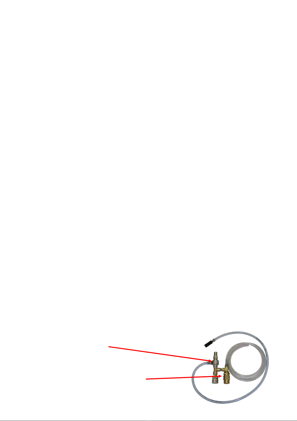
Operation of accessories of the high-pressure cleaner MBH in suction mode:
1. Connection of hoses:
-For suction mode connect supplied return valve in front of the
filter. The arrow must point towards the device. The suction hose
must be coupled to the return valve.
-A second water supply with pressure must be connected to the
right hand Geka-coupling.
2. Suction:
-Open water by activating the torch and let air flow out.
-Swich device to operational readiness and activate the torch
briefly and release again. Repeat until the lance emits a steady-
going water jet.
-For normal operation with water system pressure, mount the
supplied Geka-coupling to the Geka-connection, instead of a
hose.
5. Mode of operation
The high-pressure pump is driven by an electric motor and is supplied with water through a hose, directly
or through a feed tank, increases the pressure to the required operating pressure and leads the water
through the high-pressure hose to the torch or jet spraying device. A special nozzle generates a fan-
shaped spray sheet with the best possible cleaning effect.
During breaks the pressure circulation valve (by-pass valve) leads the water conveyed by the high-
pressure pump in circulation mode back to the suction side of the high-pressure pump.
Standard equipment: The electric motor can be turned on and off by the star/ triangle switch
(standard).
Control: The device automatically turns on once the water tap is open and
the operational availibility is turned on when the torch is activated and turns off
automatically during breaks and an overtravel time of approx. 30 sec.
The motor is protected by an motor protection relay.
Always turn off the operational readiness during long breaks!
6. Shutdown
-Turn off operating switch.
-Release high-pressure pump by activating the torch!
-Lock high-pressure torch!
-Close water tap.

page 7 of 10
7. Maintenance
7.1 Before each use
-Check the power supply cable. The cable must not be damaged (risk of electric shock). An authorised
electrician must replace the damaged power lead immediately.
-Check high-pressure hose for damages (risk of bursting); if damaged replace immediately.
Measures at risk of frost: Store the device safe from frost!
7.2 Service notes on high-pressure pump (drawing)
-Tighten screw (pos. 1 in drawing HE006W/HE007W, appendix) with 50 Nm (5.1 kgm)
-Tighten valve cover (pos. 3 in drawing HE006W/HE007W, appendix) with 68 Nm (6. kgm)
-Tighten nut bolt (pos. 17 in drawing HE006W/HE007W, appendix) with 12 Nm (1.2 kgm)
-Tighten rod bolt with 10.4 Nm (1.1 kgm)
-Tighten bearing screw (pos. 28 in drawing HE006W/HE007W, appendix) with 24.5 Nm (2.5 kgm)
7.3 Oil level high-pressure pump (check regularly)
-Check the oil level in the crankcase before starting operation of the cleaner.
-Check with oil dipstick.
-Check in fresh oil tank approx. 2 cm.
-First oil change after approx. 50 hours of operation, subsequently every 300 operating hours or every
6 months.
Oil change: - Open oil-drain screw.
- Let oil drain off into collecting tray.
- Close oil-drain screw.
- Fill in new oil slowly, oil must reach the middle of the oil level indicator.
Applicable oil: SAE 10W-60 fully synthetic ( tem.-No.: WB0011-01)
7.4 Filter
The standard water filter is on the backside of the device at the water inlet connection behind the Geka-
coupling towards the high-pressure pump.
Check the filter regularly (at least 1 x daily) and clean if applicable. Screw off the filter casing and rinse
filter.
Contaminated filters lead to water shortages and therefore damages the pump.
8. Standard accessories
8.1 High-grade steel cover
Take off cover for maintenance work:
-Extra equipment „hose coiler“: Disconnect connection hose from device to hose coiler at the
swivel joint.
-Unfasten 4 fixing screws mit PVC head on the right and left side of the device chassis (do
not unscrew completely).
-Remove cover frontwards.

page 8 of 10
8.2 Hose coiler
The hose coiler is extra equipment and supplied only on request. The coiler is made of high-grade steel and
contains the following components:
-hose drum
-holder
-swivel joint
-crank handle
-hose brake
Hose brake:
The hose brake is adjusted or completely clamped with the clamping pintle on the right side of the device.
We recommend to clamp the hose coiler during cleaning operation to prevent unwinding caused by
vibration.
Dismantling:
The hose coiler can be completely dismantled with the handle for car transportation to allow easy and
comfortable loading over a ramp.
Proceeding:
-Uncouple connection hose from device to hose coiler at the swivel joint of the hose coiler.
-Unfasten 4 fixing screws with PVC head on the back side of the device (do not unscrew completely).
-Remove electric cable from the holder on the side of the handle.
-Remove handle with hose coiler.
8.3 Special lances
Special lances are extra equipment and supplied on request. Lances can be changed with the KEW fast
coupling system on the torch.
The double lance allows stageless pressure adjustment with the handle.
The dirt blaster lance is suitable for very heavy contamination. The rotating pencil-jet generates a very
aggressive cleaning jet. Clean only suitable surfaces which are resistant to the strong jet.
The foam lance is used for foam output which is injected to the lance from the solution tank.
9 njector with coupling
Models: HZ07701 f. MBH1260 (jet size, screw-on: 2.1 mm)
HZ07702 f. MBH1800 (jet size, screw-on: 2.3 mm)
HZ07703 f. MBH2400 (jet size, screw-on: 1. mm incl. pressure relief valve)
9.1 Use:
-Injectors of type series HZ077 are designed for coupling between
device and hose or hose drum at the pressure side of the high-pressure
cleaner.
When using a stationary high-pressure line coupling is made between
tap and high-pressure hose (ill. right hand side: HZ07701/02).
-The connection for chemicals with integrated non-return valve is
located at the injector followed by the suction hose with intake
strainer to aspirate the agent from an external container. Arrows
indicate the direction of flow.
-Select the suitable injector depending on the high-pressure cleaner model to ensure the correct rate of
flow (see table „Models“).
page 9 of 10
-The injector serves the targeted feeding of cleaning agents to the water and the rinsing operation with
water.
-Suitable dosing media are fluids of group 2 of the pressure equipment directive (Druckgeräterichtlinie
DGRL).
9.2 General safety information:
-The injector must only be used with bypass and in accordance with this operation manual to ensure
safe operation.
-Keep the operation manual in a safe place for future use.
-Please also observe the safety advices of the cleaning agent and the high-pressure cleaner.
-Do not mix cleaning agents.
-Wear proper protective clothing and gloves during operation.
-Do not direct the high-pressure jet towards persons or animals.
-The device must only be operated by qualified and trained persons who do not have any limited
physical, sensory or mental capacities. Qualified staff are such persons who are familiar with
installation, start-up and shutting-down, operation, maintenance and repair of the device.
9.3 Commissioning:
All connection lines and the injector should be rinsed with clear water prior to operation or change of
medium. Please ask the producer if cleaning agents are very aggressive. Any operation exceeding the above
mentioned is not permitted.
9. .1 Connecting the injector
-Switch off the main switch of the high-pressure device.
-Afterward disconnect the fast coupling connection between device and hose or hose drum (KEW
coupling system).
When using a stationary high-pressure line coupling must be between tap and high-pressure hose.
Couple the injector in flow direction between device and hose.
-Insert the suction hose into the medium container.
.3.2 Selecting the lance
The output lance must be a double lance for pressure relief or foam lance HZ07 Z01. It is necessary to
ensure a pressure loss of at least 50 bar in flow direction behind the injector. Otherwise the injector does
not aspirate any medium.
-Do not use single flat jet lance or dirt blaster lance.
9. . Start of injection
-The device is ready for operation selection of suitable output lance and coupling the lance to the spray
gun.
-Activate the spray gun until no more air is released from the lance. Afterwards the high-pressure device
can then be switched on and the injector is ready for operation.
9.4 Dosing amount:
The dosing amount can be adjusted with the appropriate jet for chemicals
at the injection point of the injector. Dosing inserts from 0.5 to 2.0 mm
are included in the scope of delivery.
9.5 Operation with MBH2400:
Because of the high flow rate of the MBH2400 the scope of delivery
includes an extra pressure relief valve in addition to the injector.

page 10 of 10
The valve drains off excess water to prevent damages to the control
valve of the high-pressure device.
9.6 Foam lance for injector:
The metered medium can be sprayed with the double lance. The foam lance HZ07 Z01 with integrated air
injector is used for foaming. Connect this lance to the high-pressure gun with the supplied KEW-fitting.
9.7 Troubleshooting:
Injector does not aspirate any medium or does not develop any foam:
-Clogged dosing nozzle – Clean nozzle carefully with a thin wire. Replace nozzle in case of heavy soiling.
-No dosing nozzle installed in suction hose.
-Damaged suction hose.
-Suction hose not correctly inserted into medium.
-Wrong lance –operation requires either double lance with lower set pressure or foam lance HZ07 Z01.
-Wrong flow direction: Check the arrows at the injector indicating the direction of flow.
Flow directions differ depending on whether coupling at the tap or direct connection to the high-
pressure device.
Do you have any questions?
We would be glad to help. Please call us! Tel.:+49 (0) 5262 / 993 99-0
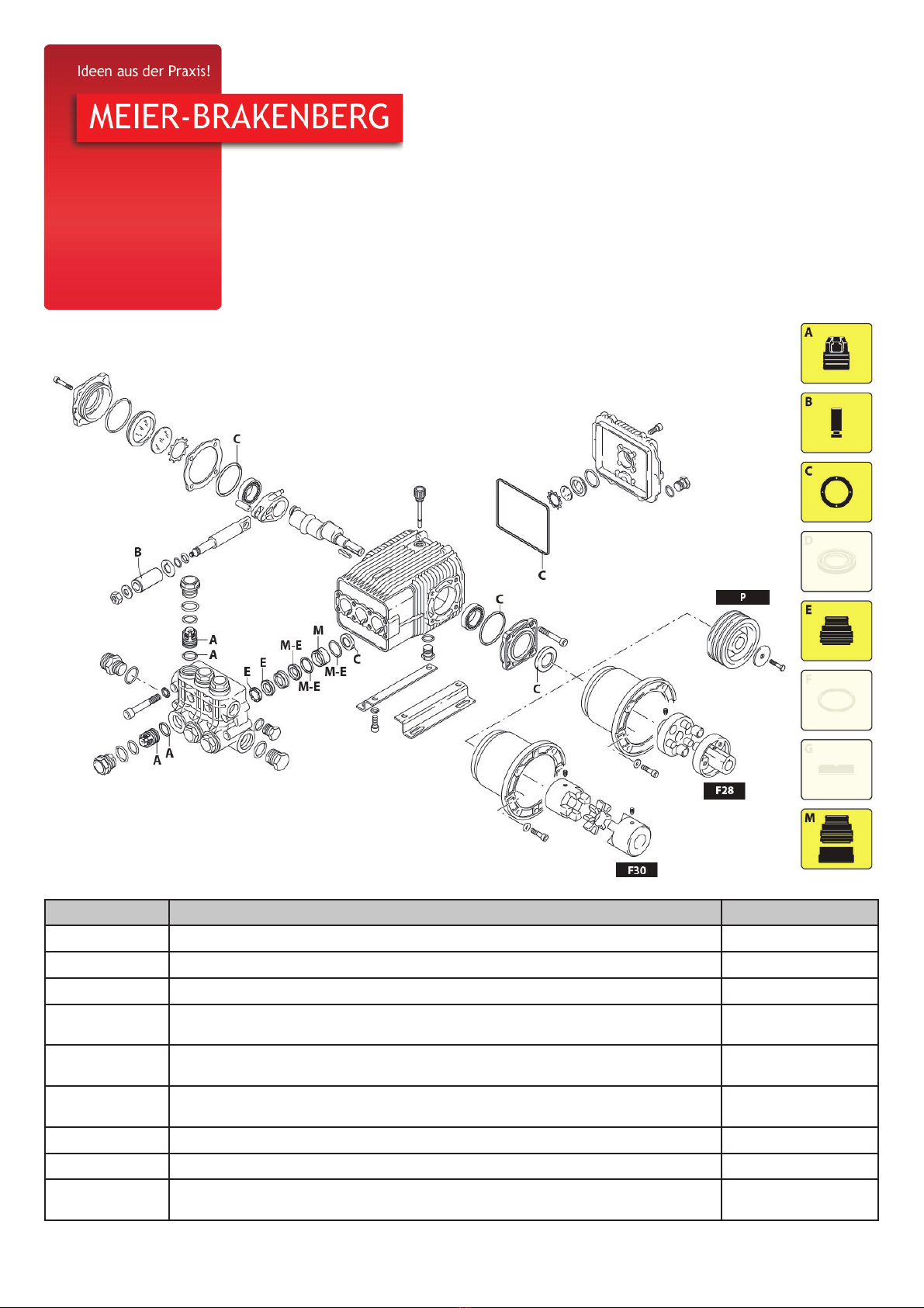
Ersatzteilliste HD-Pumpe HE006 / HE003
passend für:
MBH1500 (HE003) • MBHST1500 (HE003)•
MBH1800 (HE006) • MBHST1800 (HE006)•
MBH2400 (HE006) • MBHST2400 (HE006)•
Kit-Nummer Bezeichnung Artikelnummer
ARep.Satz Ventile für Pumpe HE006/HE003 (Pos. 5 + 6) HE006E-A
B Kolbenkit für Pumpe HE006 (Pos. 19) HE006E-B
CDichtsatz für Pumpe HE006/HE003, Ölseite (Pos. 25, 37, 42, 43) HE006E-C
DDichtsatz für Pumpe HE006, Wasserseite (Pos. 12, 14, 16)
- Version für Hochdruckreiniger bis Bj. 14.03.2012 -
HE006E-D
D01 Dichtsatz für Pumpe HE006, Wasserseite (Pos. 87, 14, 84, 85, 86, 16)
- Umbausatz alte auf neue Version -
HE006E-D01
EDichtsatz für Pumpe HE006, Wasserseite (Pos. 14, 16, 84, 85, 87)
- Version für Hochdruckreiniger ab Bj. 15.03.2012 -
HE006E-E
EDichtsatz für Pumpe HE003, Wasserseite (Pos. 14, 16, 84, 85, 87) HE003E-E
HRep.Satz Kolbenführung für Pumpe HE003 (Pos. 13 + 15) HE003E-H
MRep.Satz Kolbenführung mit Wasserdichtung für Pumpe HE006
(Pos. 16, 84, 85, 86)
HE006E50
Verschleißteil-Sätze HE006 und HE003 / Part-Kits HE006 and HE003
Kit-Nummer Bezeichnung Artikelnummer
3Ventilstopfen ms. an HD-Pumpe HE006 HE006E03
4Dichtring für Ventilstopfen HE006E03 HE006E04
5O-Ring Ø20,29x2,62 mm für Ventilstopfen HE006E03 HE006E05
8O-Ring an Stopfen Eingang 23,81 x 2,62 HE006E08
10 Stopfen ms. 3/8“, an Pumpe HE006 HE006E10
13 Front-Kolbenführung f. Pumpe HE006 HE006E13
14 Dichtring Wasser, braun, an Pumpe HE006 HE006E14
18 Kupferscheibe/Ring f. Keramikkolben in Pumpe HE006 HE006E18
16 O-Ring aus Dichtsatz HE006E-D, 37,82 x 1,78 HE006E16
20 O-Ring, 9,25 x 1,78 HE006E20
22 Ring, f. Pumpe HE006, Pos. 22 HE006E22
23 Pleuel in Messing f. Pumpe HE006, Pos. 23 HE006E23
25 Dichtring 66,34 x 2,62 NBR, an Pumpe HE006 HE006E25
29 Kegelrollenlager Typ: 32206, f. Pumpe HE006, Pos. 29 HE006E29
32 Kurbelwelle für HD-Pumpe HE006, Wellentyp: 3 HE006E32
34 Ölpeilstab für HD-Pumpe HE006/W, Länge 80 mm, 3/8“ IG HE006E34
42 Dichtring 30x52x7 für Pumpe HE006 HE006E42
60 Pumpenkopf Messing, kpl. mit Dichtungen und Ventileb, f. Pum-
pe HE006 (Pos. 60)
HE006E60
86 Kolbenführung hinten f. Pumpe HE006, Pos. 86 HE006E86
Standard-Einzelersatzteile HE006 / Spareparts HE006

Standard-Einzelersatzteile HE003 / Spareparts HE003
Artikelnummer der Einzelteile siehe Einzelersatzteile HE006 /
Item-No. of individual components see spareparts HE006
Abmessungen Pumpe HE006/HE003
Dimensions pump HE006/HE003
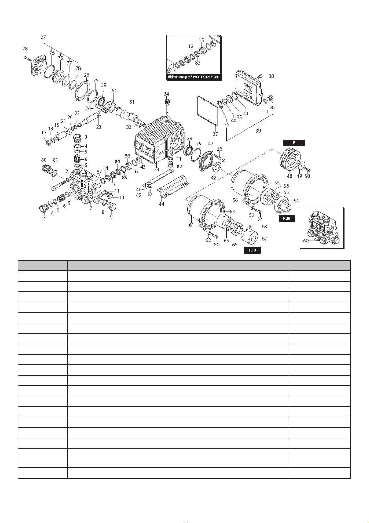
Ersatzteilliste HD-Motorpumpe HE007
passend für:
MBH1260K•
MBHST1260•
Kit-Nummer Bezeichnung Artikelnummer
ARep.Satz Ventile für Motorpumpe HE007 HE004E006
BKolbenkit für Motorpumpe HE007, Ø22 mm HE004E005
CDichtsatz für Pumpe HE007, Ölseite, Ø22 mm HE004E007
EDichtsatz für Pumpe HE007, Wasserseite, Ø22 mm HE004E002
G Rep.Satz Kolbenführung/Stützring, Ø22 mm HE004E004
HE-Motor 5,5 kW, 230-400V/50Hz, einzeln HE007E01
HD-Pumpe 21 l/min., 150 bar bei 1.450 U/min. HE004
Verschleißteil-Sätze HE007 / Part-Kits HE007

Standard-Einzelersatzteile HE007 und HE004 / Spareparts HE007 and HE004
Kit-Nummer Bezeichnung Artikelnummer
1O-Ring 17,86 x 2,62 mm HE008E12
13 Kolbenführung 22 mm für Pumpe HE004, Pos. 13 HE004E013
20 Lager für Pumpe HE004, Pos. 20 HE004E020
22 Öl-Peilstab für Motorpumpe HE007 HE004E001
24 Kupferscheibe/Ring f. Keramikkolben in Pumpe HE004 HE004E024
25 Keramikkolben einzeln für Pumpe HE004, Ø22 HE004E003
27 O-Ring für Pumpe HE004, Größe: 7,66x1,78 mm, Pos. 27 HE004E027
77 Lager für Pumpe HE004, Pos. 77 HE004E077
78 Pumpenkopf Messing vernickelt kpl. mit Dichtungen HE004E078
Abmessungen Motorumpe HE007 / Dimensions motor-pump HE007

Ersatzteilliste Regelventil HE008, passend für:
Alle MBH•
Alle MBHST•
Standard-Einzelersatzteile /Spareparts HE008
Kit-Nummer Bezeichnung Artikelnummer
9O-Ring Ø 5,94 x 3,53 HE008E09
10 Düse in Regelventil HE008E10
11 Feder 9,5x17,5x0,7 HE008E11
12 O-Ring Ø 17,86 x 2,62 HE008E12
13 Gewindeadapter 3/8“ AG HE008E13
14 Feder 21x50x6 HE008E14
16 Kolben HE008E16
21 Kolbenführung HE008E21
22 O-Ring Ø 23,81x2,62 HE008E22
23 O-Ring Ø 9,25x 1,78 HE008E23
Rep.Kit für Regelventil HE008 (Pos.: 5, 6, 9, 12, 15, 17, 18, 19, 20, 22, 23) HE008E30
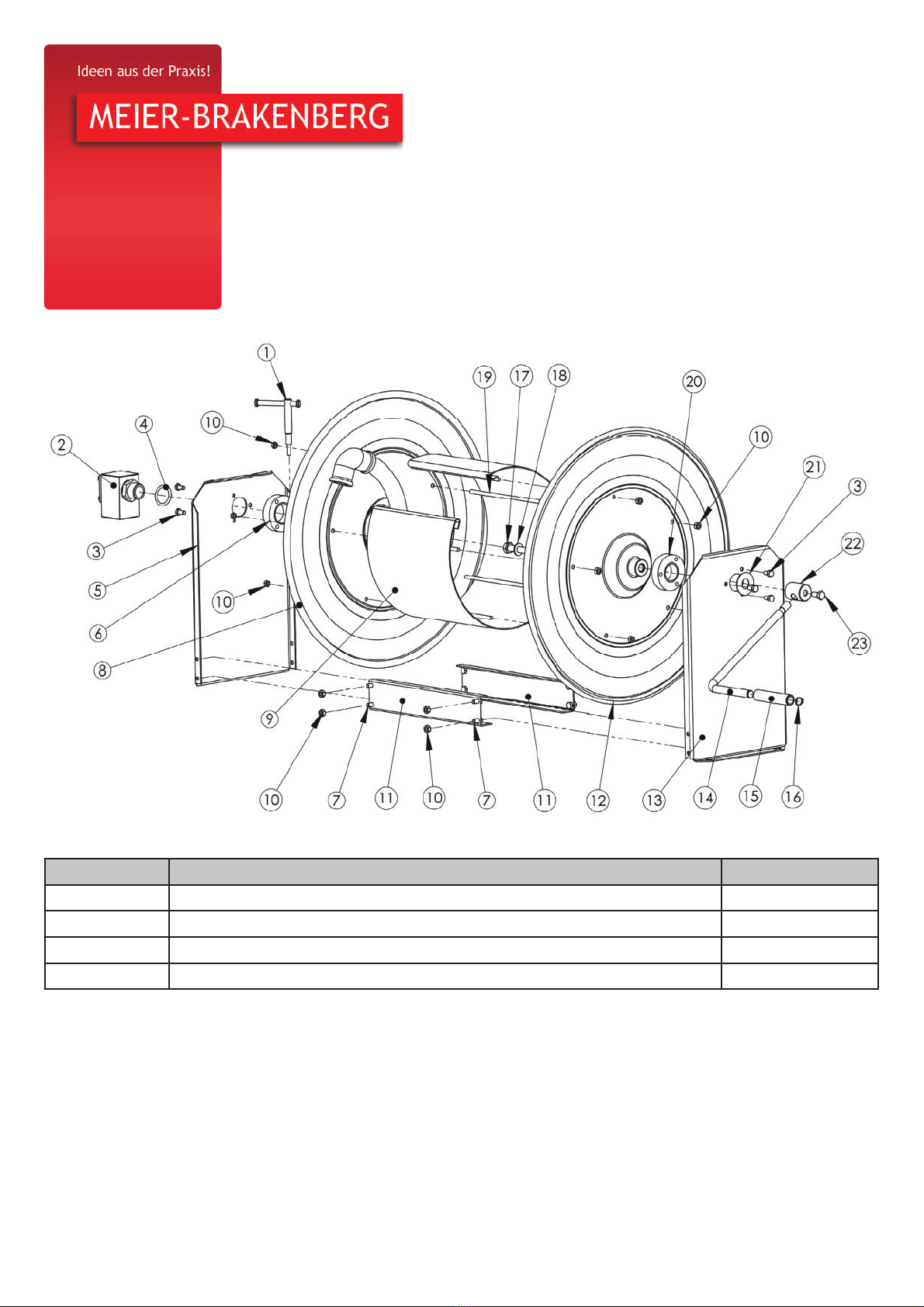
Explosionszeichung Schlauchroller HST
Modelle:
HST30•
HST70•
HST100•
Bestellungen/technische Fragen: +49(0)52 62 / 993 99-0
MEIER-BRAKENBERG GmbH &Co. KG •Brakenberg 29 •32699 Extertal
Kit-Nummer Bezeichnung Artikelnummer
8Trommelseite rechts 1/2", 3/4" und 1" HE016E002
12 Trommelseite links kpl. 1/2“ HE016E001
15 PVC-Griff an Kurbel für Schlauchroller HE016 HE016E004
16 Sprengring an Kurbel für Schlauchroller HE016 HE016E003

Ersatzteilliste HD-Pistole HP001, passend für:
Alle MBH•
Alle MBHST•
Standard-Einzelersatzteile / Spareparts
Nr. Bezeichnung Art.-Nr.
2Frontstecker M10 x 1, Messing HP001E02
3Stützring 3,2 x 7,5 x 1,2 mm HP001E03
4O-Ring 2,62 x 2,84 mm HP001E04
5O- Ring, 1,78 x 12,42 mm HP001E05
7 Feder 1,6x8,8x24 mm HP001E07
8Kugel 13/32“ HP001E08
9Passteller 7mm mit O- Ring HP001E09
13 Gehäuseschraube 3,5 x 19, VA VBL3,5x19
14 Bolzen 5 x 33 mm HP001E14
15 Bolzen 5 x 22 mm HP001E15
16 Kolben 3 x 37,6 mm HP001E16
17 Umlenkhebel, schwarz HP001E17
18 Bolzen 4 x 29, schwarz HP001E18
19 Gestänge, schwarz HP001E19
Nr. Bezeichnung Art.-Nr.
20 Bolzen 4 x 20 HP001E20
21 Bolzen 4 x 13 HP001E21
22 Vorderrohr 2 x 1/4“ AG, VA, 85 mm HP017
23 Auslass-Anschluss 2 x 1/4“ IG ms. HP015
24 Eingangsgehäuse Drehgelenk, ms. HP001E24
25 Buchse 10 x 14 x 7mm HP001E25
26 Stützring 10,2 x 13,9 x 1,2 mm HP001E26
27 Pin M12 x 1,25 HP001E27
28 Ringmutter M22 x 1 HP001E28
29 Anschlussstück M12 x 1,25 3/8“ BSP HP001E29
30 O- Ring 2,4 x 9,3 mm HP001E30
31 Buchse, 12 x 20 x 6mm HP001E31
32 Drehgelenk und Rohr 3/8“ IG HP001E32
Ersatz-Kit für Pistole HP001 inkl.
Dichtungen für Drehgelenk
HP014

Ersatzteilliste Schaumlanze HZLS01, HZLS03
passend für:
MBH1260K • MBHST1260•
MBH1800 • MBHST1800•
Standard-Einzelersatzteile / Spareparts
Nr. Bezeichnung Art.-Nr.
1Tank 2 l, 45 mm Einlass HZLSE008
2Schlauch, 5 x 8 x 270 mm PVC
durchsichtig
HZLSE011
3Waschmittel-Einstellungswelle HZLSE009
4Wassertank-Anschluss HZLSE010
5 Düseneinsatz HZLSE012
5Düseneinsatz 3,3 mm (2) HZLSE013
6O-Ring, 1 x 8 mm HZLSE014
7 Düse M8 x 1 - 2,1 mm VA HZLSE002
8Injektor-Gehäuse-LS12 HZLSE016
9Zylinderstift, 5 x 34 mm ms. HZLSE017
10 Lanzengehäuse - LS12 HZLSE018
11 Knopf - LS12 HZLSE019
12 Blende 25 x 0,5 mm VA HZLSE003
15 O-Ring 1,78 x 20,35 mm HZLSE006
16 Vordere Düse - LS12 HZLSE007
20 Filtertuch für Schaumlanze HZLS01 HZLSE101
Bestellungen/technische Fragen: +49(0)52 62 / 993 99-0
MEIER-BRAKENBERG GmbH &Co. KG •Brakenberg 29 •32699 Extertal
ACHTUNG:
Nach Schäumvorgang
Lanze intensiv mit
klarem Wasser spülen
This manual suits for next models
8
Table of contents
Other MEIER-BRAKENBERG Pressure Washer manuals


Popular Pressure Washer manuals by other brands

Villager
Villager VPW 195 Original instruction manual

Shark
Shark BR-304037 Operating instructions and parts manual

Briggs & Stratton
Briggs & Stratton 01811-0 Parts & Diagrams

Makita
Makita HW 112 manual

Villager
Villager AGM AHW 9020 Original instruction manual

KIAM
KIAM KM3700P Operation & maintenance instructions


