Meike PBSV5.1 User manual

PBS V5.1 User’s Manual
1
In order to use this device safely and correctly, please read this manual carefully before
operating it.
Please register promptly as 10.4 in user’s manual after installation.
It is V1.2 for the version number of this user's manual.
Note:
1) Please check the power supply of adapter before charging the battery. Stop using once
the voltage of the power exceeds the scope printed on the adapter.
2) Please check the power cable of charger before charging the battery. Broken or cracked
power cable may cause a fire or electric shock which may lead to casualties.
3) Please unplug the power cable and take out the battery after charging completed.
Incomplete blackout may result in the occurrence of unusual or unsafe (Such as:
thunder strike and static electric fire, etc.)
4) Attentions before turning on the device:
a. Make sure the probe connect tightly with mainframe;
b. Make sure you have good battery, put it into battery case and lock the cover.
5) Turn off the power after finishing using.
6) Do not be away from the device while it is being used.
7) Please calibrate the date and time before first time using (or not using this device for a
long time).
8) The system will enter the energy-saving mode without any operation on the device for
about 5 minutes if not in the pre-scan mode or touch screen calibration interface. The
system will automatically shut down without any operation on the device for 10
minutes.
9) The battery should be taken out from the device if not using for a long time.
10) Stop using the device and turn it off in stormy weather; do not use the charger and cut
off the power, take out the battery in such weather.
11) Please stop charging battery and cut off power, when charging battery or using device,
if any irregularities occur as follows:
a. Abnormal noise;
b. Sudden fume or burnt odor
c. Brightness of the display screen is too high.

PBS V5.1 User’s Manual
2
12) If power adapter is damaged, please contact the manufacturer for replacement or
purchase the adapter which must be in conformity with the standard IEC 60601-1.
Using any non-compliant adapter may be dangerous.
13) PBSV5.1 Palm bladder scanner comply the relevant requirements of IEC60601-1-2
standard electromagnetic compatibility.
14) The user needs to install and use the device according to electromagnetic compatibility
information provided by the accompanying documents.
15) Portable and mobile RF communication devices may affect the performance of PBSV5.1
Palm bladder scanner. Please avoid these strong electromagnetic interference such as
mobile phones and microwave ovens, etc.
16) Guidance and manufacturer’s declaration stated in the appendix.
Warning:
1) Please read the instructions in Appendix C carefully when using the battery.
2) The maintenance service must be carried out by professional technicians. Users are not
allowed to disassemble the device. Or it may increase the maintenance difficulty and
cost, and even cause potential safety hazard.
3) Only trained doctors or authorized people by the medical institutions can use the PBS
V5.1. The users must fully study the User’s manual and understand all the instructions
before operating it. It will make the device abnormal or the practice result incorrect if
it is not followed by the instructions during the operation. To obtain the latest vision of
the User’s manual, please contact the distributor in your region.
4) The ultrasound is safe in the low acoustic power condition. Its safety has not yet been
fully confirmed in case of high acoustic power and long-time ultrasonic irradiation.
Please choose the lowest acoustic power and the shortest time to use.
5) In general situation, the heat of probe will not bring any uncomfortable feeling on
patients. However, if the environment temperature is too high (e.g. in summer), or the
probe is continuous used for a long time, the surface temperature of probe acoustic
window might increase(when the environment temperature is 40 ℃, the highest
surface temperature is less than 45 ℃), which might make the patients uncomfortable.
So per-scan will not be suggested to use for a long time while using the device,

PBS V5.1 User’s Manual
3
especially when the environment temperature is too high, the probe should not be in
contact with the patient for more than 1 minute!
6) To avoid interference or influence of electromagnetic radiation, do not use this device
together with other medical electrical equipment.
7) The device is not allowed to use together with high-frequency surgical equipment.
8) Don’t pull out the probe while using the device.
9) PBSV5.1 Palm bladder scanner should not be close to or stacked with other equipment.
If adjacent or stacked use is necessary, it should be observed to verify normal
operation in the configuration.
10) Class A equipment is intended for use in an industrial environment. The PBSV5.1 Palm
bladder scanner may have potential difficulties in ensuring electromagnetic
compatibility in other environments, due to conducted as well as radiated
disturbances.
11) Do not use your finger or hold the tool to touch the touchable connector contacts
(including the USB-B interface, probe interface, etc.) marked with the ESD warning
symbol unless you have used the device such as the electrostatic release device for
electrostatic protection.

PBS V5.1 User’s Manual
4
This manual includes user’s manual and technical instruction
Thanks for your attention
Mianyang Meike Electronic Equipment Co., Ltd.
Registered Add.: A214#, No. 133, Mianxing East Road, High-tech District, Mianyang
Manufacturing Add.: No.63, Yinping Road, Longmen Town, Fucheng District Mianyang Sichuan,
CHINA
Contact Add.: No.63, Yinping Road, Longmen Town, Fucheng District, Mianyang Sichuan, CHINA
Post Code: 621000
Service Call: 0816-6355073
Sales Call: 0816-6355073
Fax: 0816-6355070
Website: www.bladder-scanner.com
Email: meike01@bladder-scanner.com
2460
EC│REP
Lotus NL B.V.
Koningin Julianaplein 10,le Verd,2595AA,The Hague,Netherlands.

PBS V5.1 User’s Manual
5
Revision History
Version
Date
Description
V1.0
2017.08
First Edition
V1.1
2018.10
Add the illustration for not configuring wireless
related hardware
V1.2
2019.03
To change the background icon into "ready" icon of
the schematic diagram for the main interface on
Fig 7-3.

PBS V5.1 User’s Manual
6
Contents
CHAPTER 1 OVERVIEW...................................................................................................................................... 1
1.1 FEATURE........................................................................................................................................................... 1
1.2 STRUCTURE .......................................................................................................................................................1
1.3 SCOPE OF APPLICATION.........................................................................................................错误!未定义书签。
1.4 CONTRAINDICATION............................................................................................................................................ 1
1.5 ILLUSTRATION ABOUT SIGN OF INTERFACE ON THE DEVICE ........................................................................................... 2
1.6 DESCRIPTION OF THE ACOUSTIC OUTPUT: ................................................................................................................ 2
CHAPTER 2 TECHNICAL SPECIFICATION............................................................................................................. 4
2.1 MAIN TECHNICAL SPECIFICATION ...........................................................................................................................4
2.2 THE MAIN FUNCTION........................................................................................................................................... 4
CHAPTER 3 SYSTEM PRINCIPLE ......................................................................................................................... 7
3.1 PRINCIPLE:........................................................................................................................................................ 7
3.2 SYSTEM COMPONENTS ........................................................................................................................................ 7
3.3 PICTURES OF THE DEVICE......................................................................................................................................9
3.4 CIRCUIT DIAGRAM AND COMPONENTS LIST DESCRIPTION......................................................................................... 10
CHAPTER 4 CONTROL PANEL............................................................................................................................12
4.1 CONTROL PANEL ..............................................................................................................................................12
CHAPTER 5 ENVIRONMENTAL REQUIREMENT .................................................................................................13
5.1 ENVIRONMENTAL REQUIREMENT FOR DEVICE USE ...................................................................................................13
5.2 ENVIRONMENT REQUIREMENT FOR DEVICE STORAGE ...............................................................................................13
5.3 ENVIRONMENT REQUIREMENT FOR TRANSPORTATION.............................................................................................. 13
CHAPTER 6 DEVICE INSTALLATION...................................................................................................................14
6.1 CHECK AFTER OPENING THE CARTON..................................................................................................................... 14
6.2 DEVICE INSTALLATION........................................................................................................................................14
CHAPTER 7 OPERATION MANUAL....................................................................................................................17
7.1 PREPARATION BEFORE SWITCHING ON THE DEVICE ..................................................................................................17

PBS V5.1 User’s Manual
7
7.2 SWITCH ON/OFF THE DEVICE...............................................................................................................................17
7.3 LOGIN INTERFACE.............................................................................................................................................17
7.4 MAIN SYSTEM INTERFACE ..................................................................................................................................18
7.5 PRE-SCAN INTERFACE AND SCAN INTERFACE........................................................................................................... 21
7.6 SCAN RESULT INTERFACE....................................................................................................................................22
7.7 SCANNING RESULTS TWO-COLOR INTERFACE AND GRAYSCALE INTERFACE.....................................................................24
7.8 RESULT CORRECTION INTERFACE .........................................................................................................................25
7.9 SAVE &EDIT INTERFACE .................................................................................................................................... 26
7.10 BROWSE HISTORICAL RECORD INTERFACE...............................................................................................................27
7.11 CHECK RECORD DETAIL INTERFACE.......................................................................................................................29
7.12 SYSTEM RESET INTERFACE ..................................................................................................................................30
7.13 DEVICE VERIFICATION INTERFACE ......................................................................................................................... 45
7.14 LOCATION PROMPT...........................................................................................................................................46
7.15 TEST RECORD PRINTING ..................................................................................................................................... 47
7.16 THERMAL PRINTER............................................................................................................................................48
7.17 TEST RECORD EXPORT .......................................................................................................................................48
7.18 ENERGY SAVING MODE .....................................................................................................................................49
7.19 OVER TEMPERATURE TIPS................................................................................................................................... 50
7.20 BATTERY RECHARGING.......................................................................................................................................50
CHAPTER 8 CLINICAL APPLICATION..................................................................................................................53
8.1 OPERATION STEPS:........................................................................................................................................... 53
8.2 BLADDER PROFILE ENVELOPE............................................................................................................................... 53
CHAPTER 9 TRANSPORTATION AND STORAGE.................................................................................................56
9.1 TRANSPORTATION ............................................................................................................................................56
9.2 STORAGE ........................................................................................................................................................56
CHAPTER 10 MAINTENANCE AND SERVICE ........................................................................................................57

PBS V5.1 User’s Manual
8
10.1 MAINTENANCE FOR PROBE.................................................................................................................................57
10.2 MAINTENANCE FOR DEVICE ................................................................................................................................ 57
10.3 SERVICE GUIDE................................................................................................................................................. 57
10.4 REGISTER METHOD ........................................................................................................................................... 58
10.5 PRODUCTION DATE ........................................................................................................................................... 58
CHAPTER 11 SIMPLE PROBLEM ELIMINATION ...................................................................................................59
APPENDIX A PROBE CALIBRATION......................................................................................................................60
APPENDIX B VOLUME CALIBRATION...................................................................................................................63
APPENDIX C PRECAUTIONS FOR 18650 BATTERY USE.........................................................................................66
APPENDIX D GUIDANCE AND MANUFACTURER’S DECLARATION........................................................................69

PBS V5.1 User’s Manual
1
Chapter 1 Overview
1.1 Feature
PBSV5.1 Palm bladder scanner is used for measuring bladder volume with its ultrasonic
echo. It consists of data processing of main frame and ultrasonic probe. Its display is color
TFT-LCD with Pixel 800×600, and its measurement results can be printed out with thermal
printer and also can be stored in the built-in flash-disk. The measurement results stored in
flash-disk can be sent to the computer through USB interface in the main frame.
The device is strict in accordance with the national standard IEC 60601-1:2005+A1:2012
“Medical electrical equipment Part I: General requirements for basic safety and essential
performance” in its design and manufacture. The whole process of design, production and sale
are strictly controlled in accordance with the requirements of ISO13485:2016QMS.
The Device on the risk of electrical shock protection type:
Charging device is class II ;
The host is the internal power supply device.
The Device on the risk of electrical shock protection level:
B type applied part
1.2 Structure
PBS V5.1 is clamshell portable, mainly consisting of the host (software version PBS V5.1
V1.01), 3D probe (nominal frequency 2.6 MHz), and power adapter.
1.3 Intended use
The device is mainly applied to measure the urinary volume in human’s bladder.
1.4 Patient population
It is suitable for all the people except pregnant and fetus.
1.5 Contraindication
The device is contraindicated for fetal use and for use on pregnant patients.
PBS V5.1 User’s Manual
2
The device is not suitable for those who are allergic to ultrasound gel and the people with
abdomen skin wound and skin disease.
1.6 Side effect and Complication
N/A
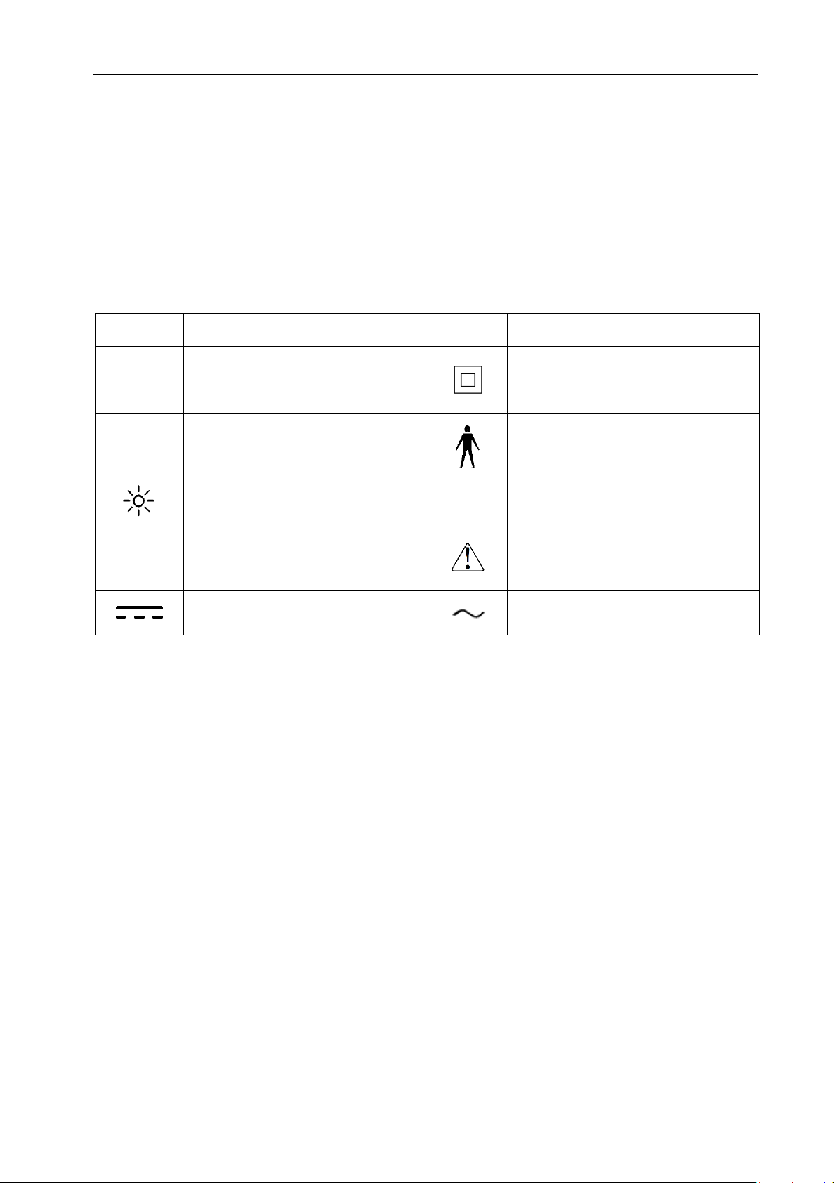
1.7 Illustration about sign of interface on the device
Sign
Meaning
Sign
Meaning
+
18650 battery positive direction.
Class II equipment
-
18650 battery negative direction.
Type B application
Power indicator
Level of liquid protection.
Electrostatic sensitive device
Attention! Check the documents
attached with the device
Direct current (dc)
Alternating current (ac)
1.8 Description of the acoustic output:
1)The device is in accordance with IEC 60601-2-37:2007+A1:2015 “Part 2-37 :Particular
requirements for the safety of ultrasonic medical diagnostic and monitoring equipment”
201.7.9.3.101 Technical data regarding acoustic output levels:
Transducer frequency: 2.6 MHz

PBS V5.1 User’s Manual
3
Fig 1-1 Technical Data Sheet for level of acoustic output
2)Device accords with requirements of IEC 60601-2-37:2007+A1:2015 “Part 2-37 :
Particular requirements for the safety of ultrasonic medical diagnostic and monitoring
equipment”201.12.4.2 a) ,b) . Exempted from showing MI, TI.
MI <1
TI<1

PBS V5.1 User’s Manual
4
Chapter 2 Technical Specification
2.1 Main technical specification
2.1.1 Frequency of acoustic work.
The deviation between acoustic working frequency and nominal frequency should be
within ±15%.
2.1.2 Probe type.
Mechanical sector scanning.
2.1.3 Transducer: 2.6 MHz;
2.1.4 Detect depth: ≥140 mm;
2.1.5 Scope of Measurement volume: 0 ml~ 999 ml;
2.1.6 Measurement accuracy:±15%,±15 ml(on a Meike tissue-equivalent phantom)
2.1.7 The display unit of volume measurement results: ml
2.1.8 Structure form: clamshell
2.1.9 Power supply voltage adaption range.
Main unit:DC7.4V,Four 3.7v 18650 li-ion batteries meeting the IEC 62133 standard
are used for power supply
Power adapter: AC 100V~240V 50Hz/60Hz
2.1.10 Continuous working time :≥ 2 H(Replaceable battery)
2.2 The main function
2.2.1 Functional requirements
1) Storage capacity: 100 cases.
2) Display mode: B, 12 B.
3) Image processing: gray scale display, 2-color images.
4) Case management: storage, browse, export.
5) Measurement function: automatic measurement of bladder volume and display
results.

PBS V5.1 User’s Manual
5
6) Input interface: one probe interface; one bar code scanning interface; one charging
interface.
7) Output interface: one USB interface.
2.2.2 Equipment software function
NO.
Software function item
1
Software normal switching machine.
2
Login In
3
Status bar
display
Display mode (expert/easy)
4
Printer status
5
Probe connection status.
6
Sound state.
7
Storage of residual space detection and display.
8
Network status display.
9
Battery calibration indication
10
Date display
11
Operator ID display.
12
Patient ID input (Barcode scanning entry)
13
The gender switch
14
Browse the test record list.
15
Upload test record
16
For details of the inspection records.
17
Print test record
18
Delete test record
19
Ultrasonic pre-scan image display.
20
Ultrasonic pre-scan of bladder position.
21
Automatic scanning and calculation of results.
22
Scan and volume calculation progress tips.
23
Test results display
24
Bladder relative position target indication.
25
View the test results image.
26
Switch between grayscale and 2-color graph.
27
Bladder contour envelope correction function.
28
Print current test results and images.
29
Patient name entry.
30
Test results saved
31
Operator ID input.

PBS V5.1 User’s Manual
6
32
System
Settings
Display mode Settings
33
Scanning bit Settings.
34
Network Settings
35
Key tone switch Settings.
36
Delete all records
37
Scan mode Settings
38
The probe calibration
39
Volume calibration
40
Time, date setting.
41
Server configuration
42
Touch screen calibration
43
Equipment information display
44
Equipment calibration function
45
Temperature of overheating prompt.
46
USB export data to PC.
47
Energy saving mode
48
Automatic shutdown with no operation for 10 minutes

PBS V5.1 User’s Manual
7
Chapter 3 System Principle
3.1 Principle:
Palm bladder scanner is a medical device with high performance combined with modern
ultrasound technology and computer technology. The device consists of host and probe. It can
speedily complete the detection of bladder area through scan of probe connected with the
device, and transmit ultrasound echo signal detected to embedded computer system. The
computer system will identify the edge of image and calculate its volume, thus to achieve the
measurement of bladder volume. Also the device will display the relative information through
LED screen or print out through built-in printer.
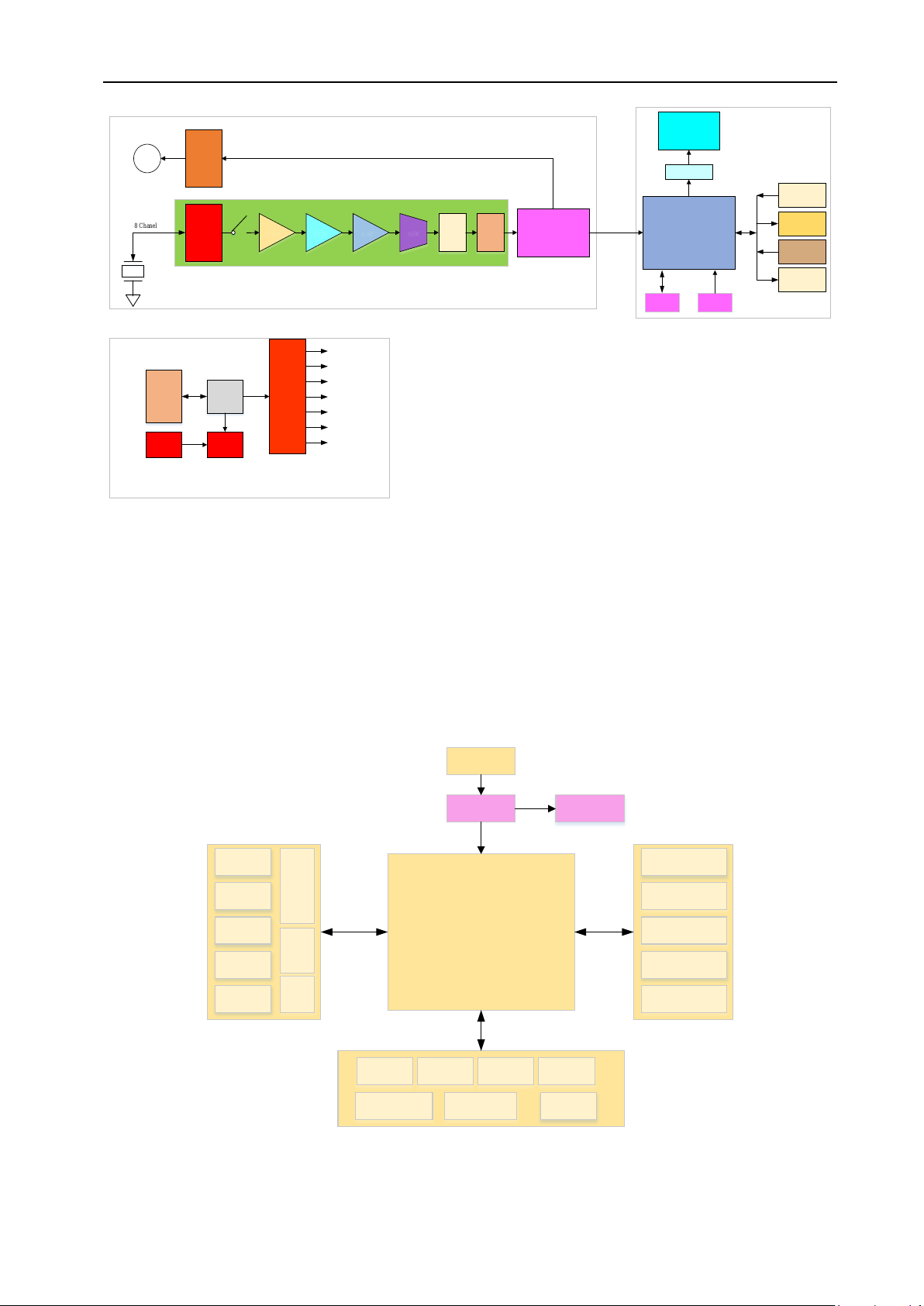
3.2 System components
3.2.1 Hardware components
The system consists of three parts, namely the signal processing part, the application
interaction part and the power management part, and its composition is shown in Figure
3-1.The signal processing part of ultrasonic signal launch out, the echo signal filtering, amplifying,
AD conversion, digital signal processing, etc., in the end by FPGA provides two-dimensional
ultrasound images for embedded microcontroller controller for the next operation; The
application of interaction part mainly has the embedded microcontroller controller MCU, the
monitor, the keyboard, the storage and other peripheral interface or equipment, mainly by the
embedded microcontroller controller MCU to complete the ultrasound image processing,
boundary recognition, volume estimation, corresponding display by various peripheral
equipment; The power management system mainly realizes the voltage of all kinds of standard
required by lithium battery charging and power supply through lithium battery.
PBS V5.1 User’s Manual
8
8 Chanel
Motor
Driver
M
Hi Pulse DHPF LVDS
Driver
LNA VGA AAF ADC FPGA MCU
LVDS Driver
TFT
Memory KEY
QR/Bar Code
Micro Printer
RTC
USB
QSPI+CMDI
Li-on
Battery
(Include
Protection)
Switch
Li-on
Charge
DC Input
9V/2A
Power
System
+5.0V/2A
+3.3V/1A
+AV5.0V/200mA
-AV5.0V/200mA
+11V/400mA
+HV/20mA
-HV/20mA
Signal Processing Application interaction
Power management
Figure 3-1 Hardware configuration
3.2.2 Embedded software system
Embedded software is based on STM32F7 system to design, using the BOOT guide and task
scheduler to perform task allocation patterns, designed a BOOT guidance system, the main task
scheduling system ,communication subsystem, interface subsystem, and core algorithm
subsystem etc., its composition is shown in figure 3-2.
UI Library
Menu
Logic
Image
Display
Data
Display
Warning
Hints Buzz
Keyb
oard
TFT
Drive
Interface
Subsystem
Main task scheduling logic system
Image Mapping
Image
Optimization
Boundary
Recognition
3D Structure
Volume
Calculation
Algorithm
Subsystem
Camera SPI USB USART
B-ultrasound
Image File Bar Code
Communication
Subsystem
Start
Boot Software
Update
Figure 3-2 Software module block diagram

PBS V5.1 User’s Manual
9
3.3 Pictures of the device
3.3.1 The picture of the device, see Figure 3-3
Figure 3-3 Device picture
①Touch screen
②Control panel
③Power indicator
④3D Probe
⑤Display panel
⑥Printer cover buckle
⑦Printer
⑧Battery cover buckle and fastening screw.
⑨Battery cover
①
②
⑤
③
⑦
④
⑥
⑧
⑨

PBS V5.1 User’s Manual
10
3.3.2 Host interface schematic diagram (See Figure 3-4 )
Figure 3-4 Host interface schematic diagram
①USB interface
②Probe interface
③Recharging interface
④The bar code scanning port
3.3.3 3D probe schematic diagram, see Figure 3-5
Figure 3-5 3D probe schematic diagram
①Probe plug
②Probe acoustic window
③Probe cable
3.4 Circuit Diagram and Components List Description
②
①
②
③
①
③
④

PBS V5.1 User’s Manual
11
In case of eligible technicians of user’s part have any need to repair device parts permitted
and indicated by our company, may apply to our company or any offices for circuit diagram,
parts list and other materials connected with the parts

PBS V5.1 User’s Manual
12
Chapter 4 Control Panel
4.1 Control Panel
Figure 4-1 Control Panel
①Scan Button
②Print Button
③Up Button
④Left Button
⑤Down Button
⑥OK Button
⑦Right Button
⑧Power Button
⑨Power Light
⑩LCD(Touch Screen)
⑪3D Probe
①
②
③
④
⑤
⑥
⑦
⑧
⑨
⑩
⑪
Table of contents
Popular Medical Equipment manuals by other brands


Getinge
Getinge Arjohuntleigh Nimbus 3 Professional Instructions for use

Mettler Electronics
Mettler Electronics Sonicator 730 Maintenance manual

Pressalit Care
Pressalit Care R1100 Mounting instruction

Denas MS
Denas MS DENAS-T operating manual

bort medical
bort medical ActiveColor quick guide

AccuVein
AccuVein AV400 user manual


