Meister Cook DMW-22-TDL User manual

DMW-22-TDL SERVICE MANUAL
For Systems Installed At:
Revision: 20150414

DMW-22-TDL SERVICE MANUAL
Confidential and proprietary information of Meister Cook, LLC. Not to be reproduced or used in any manner other than
with the express written permission of Meister Cook, LLC.
2| P a g e
TABLE OF CONTENTS
1. INTRODUCTION…………………………………………………………………………………………………………….3
2. BASIC THEORY OF OPERATION……………………………………………………………………………………..3
3. OPERATING INSTRUCTIONS………………………………………………………………………………………….5
4. REVISION HISTORY……………………………………………………………………………………………………….9
5. DIAGNOSTIC METHODS………………………………………………………………………………………………..9
6. TROUBLESHOOTING……………………………………………………………………………………………………11
7. PARTS LIST………………………………………………………………………………………………………………….14
8. WIRING DIAGRAM……………………………………………………………………………………………………..14

DMW-22-TDL SERVICE MANUAL
Confidential and proprietary information of Meister Cook, LLC. Not to be reproduced or used in any manner other than
with the express written permission of Meister Cook, LLC.
3| P a g e
1. INTRODUCTION
The purpose of this manual is to provide a guide for technical service of Meister Cook’s 2x2 Dry Moist
Warmer for Tim Hortons (model DMW-22-TDL). This manual will provide an overview of the
operation of the DMW-22-TDL, as well as a guide for troubleshooting fault symptoms.
Before getting started, it will be helpful to have the following tools and equipment:
Phillips screwdrivers - #00, #1, #2
Right-angle Phillips screwdriver - #2
Wrench and socket set
Needle nose pliers
Side-cut pliers or scissors
Plastic Cable Ties
Multimeter
Power monitor for 120VAC circuits (e.g. Kill-a-Watt, clamp-on current meter)
Heat gun
Degreasing cleaner (e.g. Goof-Off) and stainless steel cleaner
Cleaning rags –non-abrasive, lint-free
2. BASIC THEORY OF OPERATION
The DMW-22-TDL is designed to hold potentially-hazardous hot food products at safe temperatures
for an extended period of time, without degrading the quality of the food products.
The DMW-22-TDL has (2) independently-controlled heated holding chambers, each which can hold
(2) 1/3-size food pans. Underneath each chamber is a large, finned heater. Convection, provided by
a tangential blower, moves air across the heater and transfers that heat over top the food product in
the pans; the air recirculates, and continues to heat up. Also, heat from the heater is transferred to
the pan shelf, creating a hot plate.
Above each pan is a reversible moist/dry insert. In the “Dry” orientation, heated air passes directly
over the food product; this is recommended for food products that need to maintain a level of
crispiness. The dry orientation has a “third hand” feature that holds the pan in place when it is
partially removed. In the “Moist” orientation, heated air passes over the insert, effectively creating a
top hot plate; this is recommended for food products that need to maintain a level of moisture.
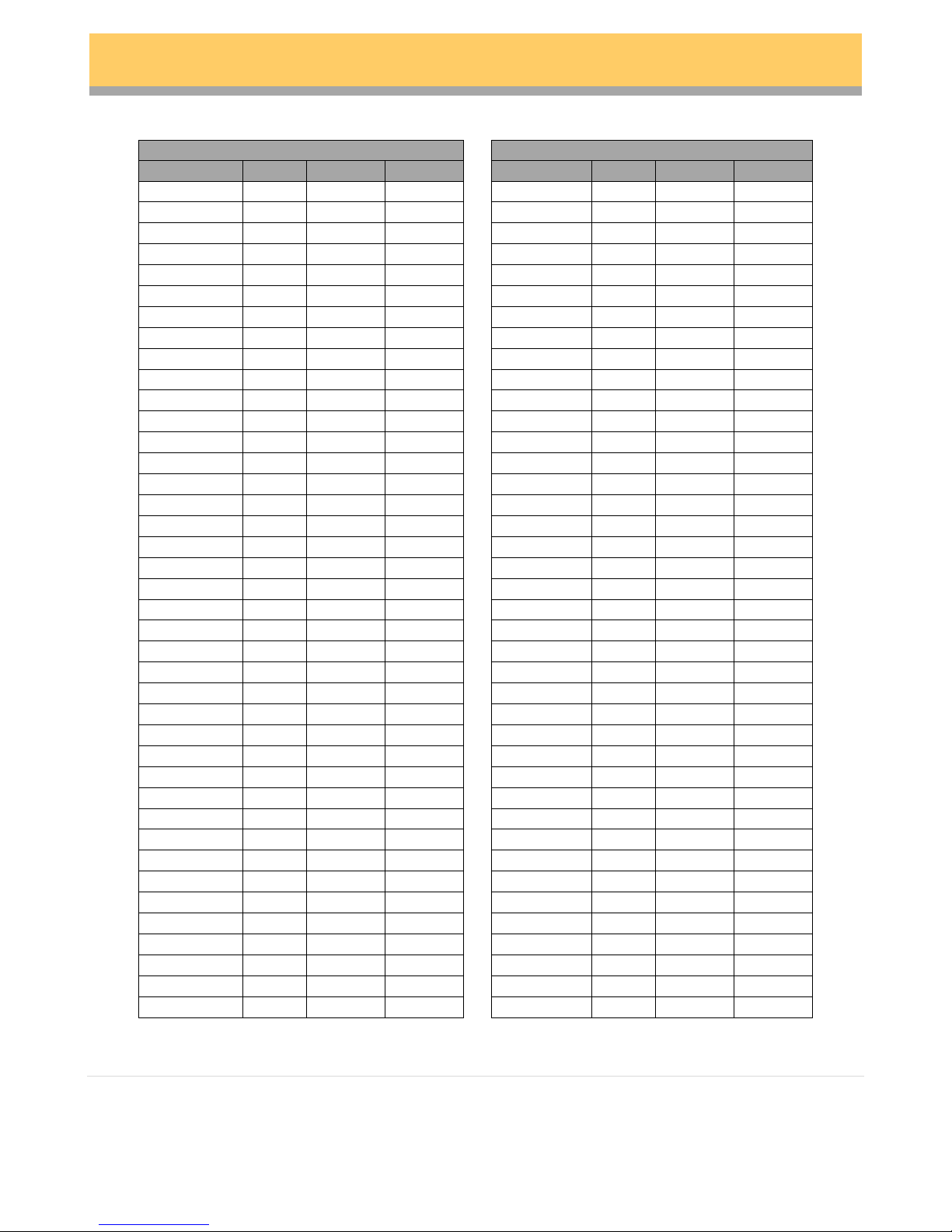
The DMW-22-TDL contains 40 factory default product presets, each of which can be modified and
saved by the operator. Each preset has a distinct 4-letter name, temperature setpoint (165F –250F),
“Cook” alert time (up to 9hrs 59min) and a “Dump” product alert time (up to 9hrs 59min). See the
table below for factory defaults.

DMW-22-TDL SERVICE MANUAL
Confidential and proprietary information of Meister Cook, LLC. Not to be reproduced or used in any manner other than
with the express written permission of Meister Cook, LLC.
4| P a g e
v1.26 Factory Default Product Presets
v1.46/v1.49 Factory Default Product Presets
Product
Temp
Dump
Cook
Product
Temp
Dump
Cook
VEG1
185
04:00
00:30
EGGS
185
04:00
00:30
EGGS
185
04:00
00:30
BACN
185
03:00
00:15
BACN
185
03:00
00:15
SAUS
185
04:00
00:30
SAUS
185
04:00
00:30
SCEG
185
02:00
00:30
HAM
185
04:00
00:30
HSBR
210
02:00
00:30
BEEF
185
04:00
01:00
HAM
185
02:00
00:30
CHIK
185
06:00
01:00
TURK
185
04:00
00:30
BCN2
185
04:00
01:00
CHKS
185
06:00
01:00
POTA
185
04:00
01:00
CCHK
210
02:00
00:30
CHC2
185
06:00
01:00
STK
185
06:00
01:00
LOAF
185
04:00
01:00
CHIP
210
08:00
00:15
BFF2
185
04:00
01:00
VEG1
185
04:00
01:00
MTBL
185
04:00
01:00
CHK2
185
06:00
01:00
FILL
185
04:00
01:00
BCN2
185
03:00
00:15
PSTA
185
04:00
01:00
CKS2
185
06:00
01:00
VEG2
185
04:00
01:00
VEG2
185
04:00
00:30
SCEG
185
02:00
00:30
PSTA
185
04:00
01:00
BCHK
200
02:00
00:30
PORK
185
06:00
01:00
CHIP
200
02:00
00:30
CCK2
210
02:00
00:30
HSBR
200
02:00
00:30
CBF
185
04:00
01:00
LEG1
185
04:00
00:30
OEUF
185
04:00
00:30
OEUF
185
04:00
00:30
BAC2
185
03:00
00:15
BAC2
185
03:00
00:15
SAU2
185
04:00
00:30
SAU2
185
04:00
00:30
OEBR
185
02:00
00:30
JAMB
185
04:00
00:30
GLPT
210
02:00
00:30
BOEU
185
04:00
01:00
JAMB
185
02:00
00:30
POUL
185
06:00
01:00
SAUD
185
04:00
00:30
BCND
185
04:00
01:00
POUL
185
06:00
01:00
PDT
185
04:00
01:00
PCRO
210
02:00
00:30
POUL
185
06:00
01:00
STK
185
06:00
01:00
PAIN
185
04:00
01:00
CROU
210
08:00
00:15
BFSA
185
04:00
01:00
LEG1
185
04:00
01:00
BOUL
185
04:00
01:00
POUL
185
06:00
01:00
VIAN
185
04:00
01:00
BAC2
185
03:00
00:15
PATE
185
04:00
01:00
POUL
185
06:00
01:00
LEG2
185
04:00
01:00
LEG1
185
04:00
00:30
OEBR
185
02:00
00:30
PATE
185
04:00
01:00
POPA
200
02:00
00:30
PORC
185
06:00
01:00
CROU
200
02:00
00:30
PCR2
210
02:00
00:30
GLPT
200
02:00
00:30
BFSA
185
04:00
01:00

DMW-22-TDL SERVICE MANUAL
Confidential and proprietary information of Meister Cook, LLC. Not to be reproduced or used in any manner other than
with the express written permission of Meister Cook, LLC.
5| P a g e
The UI has a menu of (4) product presets, (1) for each pan. These may be changed at any time. Each
row has (2) presets each. Based on which preset is selected, the highest temperature setpoint of the
two presets will determine that row’s temperature setpoint; this is why it is advised to either
program the same presets in the same row, or to program two different presets with equal
temperatures.
Also, the presets determine the countdown timers. If, in any of the 4 bins, the same preset is
selected, all timers will be based on a first-in, first-out basis; the first timer started for a given product
will flash the brightest.
There are (2) pages of menus presets, one for AM products and the other for PM products. See the
table below for factory defaults (note that v1.46 and later systems have both English and French
default menus):
v1.26 Defaults
v1.46/v1.49 Defaults
English
French
AM
EGGS
SCEG
AM
EGGS
SAUS
OEUF
SAU2
SAUS
BACN
HSBR
HSBR
GLPT
GLPT
PM
CHIK
CHIK
PM
CCHK
CCHK
PCRO
PCRO
BACN
VEG1
CHIP
CHIP
CROU
CROU
Temperature feedback is provided by a thermocouple that is placed inside each intake funnel. As
part of a temperature-control circuit with the UI Board and TC Board, the temperature is measured
and compared against a programmed setpoint. As long as the measured temperature is below the
setpoint, the UI Board will signal the Power Supply to power the heater (via Triacs) at approximately
400W. As the measured temperature approaches the setpoint, the power draw on the heater is
gradually reduced. Once the measured temperature reaches the setpoint, the control circuit will
adjust the power to the heater to maintain a constant temperature; the average power draw beyond
this point is reduced. The warm-up process will take between 25-35 minutes, depending on the
setpoint.
3. OPERATING INSTRUCTIONS
Refer to the below diagram showing the UI button layout for the DMW:

DMW-22-TDL SERVICE MANUAL
Confidential and proprietary information of Meister Cook, LLC. Not to be reproduced or used in any manner other than
with the express written permission of Meister Cook, LLC.
6| P a g e
Startup
Before turning on the DMW, allow it to warm up to room temperature before starting.
Make sure all dry/moist inserts are installed properly. Each chamber must have the inserts
installed in the same orientation.
Make sure the chamber front covers are installed.
Make sure food pans are installed. This provides for optimal efficiency and performance.
Plug the DMW into a 120V, 60Hz, 20 amp circuit, fitted with a properly grounded NEMA 5-15
outlet. A couple of precautions:
Make sure that 7.5A are available per DMW on the circuit. Overloading the circuit
can lead to a tripped circuit breaker, or even potentially a fire.
Do not use an extension cord. Extension cords are typically intended only for
temporary use, and commonly do not have enough current capacity for high power
draws. This can result in a fire.
Do not modify the plug in any manner. The DMW is outfitted with a NEMA 5-15 plug,
which provides for proper grounding of the system. Altering the plug may result in an
Bin 1
Bin 2
Bin 3
Bin 4
Down
Up
Temp
Prog
AM/PM
Time

DMW-22-TDL SERVICE MANUAL
Confidential and proprietary information of Meister Cook, LLC. Not to be reproduced or used in any manner other than
with the express written permission of Meister Cook, LLC.
7| P a g e
electrocution hazard. If there is damage to the cord or plug, the power cord must be
replaced in its entirety with a factory authorized cord.
Turn on the power switch for the DMW.
If it is desired to toggle to the English menu presets, press and hold Bin 1 while the
firmware version is displayed. The change will be confirmed by four (4) beeps.
If it is desired to toggle to the French menu presets, press and hold Bin 2 while the
firmware version is displayed. The change will be confirmed by four (4) beeps.
Verify that the desired presets are selected. Verify that the presets for each chamber share
an identical setpoint temperature. Remember, the highest temperature setpoint controls the
chamber temperature.
Allow the DMW 25-35 minutes to preheat.
Basic Operation
NOTE: after 10 seconds of inactivity, the UI will time-out and return to the home display.
To display the current temperature for each chamber:
Press and hold Temp.
NOTE: the temperatures are also automatically displayed on a scrolling basis on the
UI. This allows the operator to be able to see the temperatures even when they are
standing afar from the DMW.
To toggle between AM and PM menus:
Press and hold AM/PM until the green LED shifts position. The top LED indicates AM,
and the bottom LED indicates PM.
To toggle between presets:
Press and hold Prog.
Press Bin #.
Press + or –to scroll through the available presets.
To save, press and hold Prog. The save is confirmed by 2 beeps.
To cancel, either press AM/PM or simply wait 10 seconds for a time-out.
To set or cancel a timer:
Press and hold Bin #.
NOTE: the display will be brightly illuminated only if it is the first timer set for that
particular preset. This provides first-in/first-out functionality.
To silence a timer alert:
Press Bin #.

DMW-22-TDL SERVICE MANUAL
Confidential and proprietary information of Meister Cook, LLC. Not to be reproduced or used in any manner other than
with the express written permission of Meister Cook, LLC.
8| P a g e
Before turning on the DMW, allow it to warm up to room temperature before starting.
Editing Presets
NOTE: after 10 seconds of inactivity, the UI will time-out and return to the home display.
Press and hold Prog. This will lead to the Preset Select menu.
Press and hold Prog a second time. This will lead to the Preset Edit menu.
To select a product preset to edit:
Press + or –to scroll through the available presets.
To edit a preset’s temperature setpoint:
Press Temp.
Press + or –to adjust the temperature.
To edit more parameters, skip to the appropriate section.
To save changes and exit the Preset Edit menu, press and hold Prog. The save will be
confirmed by 2 beeps.
To exit the Preset Edit menu without saving changes, press AM/PM.
To edit a preset’s timers:
Press Time to access the Dump timer.
Press + or –to adjust the Dump timer.
Press Time a second time to access the Cook timer.
Press + or –to adjust the Cook timer.
To edit more parameters, skip to the appropriate section.
To save changes and exit the Preset Edit menu, press and hold Prog. The save will be
confirmed by 2 beeps.
To exit the Preset Edit menu without saving changes, press AM/PM.
To edit a preset’s name:
Press Prog.
Press Bin 1 to move the cursor to the left or Bin 2 to move the cursor to the
right.
Press +or –to adjust a letter.
To edit more parameters, skip to the appropriate section.
To save changes and exit the Preset Edit menu, press and hold Prog. The save will be
confirmed by 2 beeps.
To exit the Preset Edit menu without saving changes, press AM/PM.

DMW-22-TDL SERVICE MANUAL
Confidential and proprietary information of Meister Cook, LLC. Not to be reproduced or used in any manner other than
with the express written permission of Meister Cook, LLC.
9| P a g e
Restoring Factory Defaults
NOTE: this procedure should only be performed with the understanding that any saved
presets and parameters will be erased. It is strongly recommended to record any custom
presets and parameters.
With power turned off to the DMW, press and hold Bin 1.
Turn on the DMW while holding Bin 1. A series of beeps will indicate that the defaults have
been restored.
4. REVISION HISTORY
Refer to the chart below for a summary of revisions of the DMW-22-TDL (as of 2015-01-12):
Revision
Changes
Serial Numbers
A
Original release
DMW-20027 Rev A Heaters
V1.26 firmware
0001 through 0120
C / C1
DMW-20027 Rev B Heaters,
V1.46 firmware
0121 through 4522
4523 through 4864 & RMA’s
C2
Same as Rev C with V1.49 firmware
Various RMA’s
D
Funnels mount to Cabinet instead of Electronics cover
DMW-20066 6 pin TC cable
V1.46 firmware
4865 to 4937
(plus 4999 –5012*)
D1
Same as Rev D with V1.49 firmware
7716
E
Original DMW-20031 10 pin TC cable replaces DMW-20066 6
pin
4938 to current
F
Same as Rev E except V1.49 firmware
TBD-7715
NOTE: other than menu presets, there are no field adjustable firmware parameters. As of the
publication of this manual, there have been no observed instances of firmware corruption. Any
corrupt user interface or system control functions would require a hardware solution.
* These s/n’s were inadvertently duplicated during production
5. DIAGNOSTIC METHODS
As part of troubleshooting, there are several methods that can be used to diagnose reported failures.
The DMW-22-TDL has a set of on-board fault codes that indicate potential fault conditions:
FLT! 1111 –missing zero crossings detected

DMW-22-TDL SERVICE MANUAL
Confidential and proprietary information of Meister Cook, LLC. Not to be reproduced or used in any manner other than
with the express written permission of Meister Cook, LLC.
10 | P a g e
Under normal operation of the heater control circuit, AC line voltage crosses 0 Volts at a
frequency of 60Hz.
The power supply contains a circuit that monitors zero crossings.
If 16 half-cycles are not detected, the system will flag this condition and generate the error
code.
This fault is generally caused by a faulty power supply.
NOTE: this error code will ALWAYS occur at power down, as the heater control circuit ceases
to function. This is not an error and can be expected as normal.
FLT! 2222 –startup warming failure detected
Under normal preheating of the system, the measured temperature at the thermocouple
should rise a minimum of 16F over a 5 minute period.
This timer expires after the temperature reaches 120F.
This fault code is generated if the temperature measurement system does not detect a
minimum temperature rise of 8F over a 5 minute period.
NOTE: with Firmware v1.49, this timer has been extended to a 16F temperature rise over a
10 minute period.
This fault code is intended to indicate a failed heater, as well as prevent the heater from
overheating in the event of a fault in the movement of air and/or temperature control circuit.
However, certain installation conditions could potentially trigger a false flag:
Abnormally cold unit
Pans not installed during preheat
Effects of cool air from HVAC system
Effects of heat from another piece of equipment installed too close to the DMW
A false flag can be determined by performing the following steps:
Turn off the system and turn it back on after 10 seconds.
If the temperature is below 120F, the internal timer will reset. Monitor the system
temperatures to ensure that the appropriate temperature rise is achieved.
After clearing the fault detection parameters, ensure that the system reaches the
appropriate setpoint temperatures and is able to maintain temperature.
If a false flag continues to occur on systems running on Firmware v1.46, it is recommended to
replace the UI Board with one that is running on Firmware v1.49.
FLT! 3333 –over-temperature detected
The system has a maximum temperature setpoint of 250F.
To prevent system damage, this fault code is triggered if a temperature equal to or greater
than 285F is reached.
A false high temperature will also be reached if there is an open thermocouple circuit.
This is a preventive scheme to not allow the system to heat if a thermocouple circuit is
broken.

DMW-22-TDL SERVICE MANUAL
Confidential and proprietary information of Meister Cook, LLC. Not to be reproduced or used in any manner other than
with the express written permission of Meister Cook, LLC.
11 | P a g e
In addition to the fault codes, current measurement devices can also be helpful. A power meter, such
as a “Kill-a-Watt”, can measure power draw. Each heater should draw 400W during preheat, and the
power draw should gradually be reduced as the setpoint is approached. A typical power draw of
approximately 800W at startup is typical. Power draws significantly lower may indicate an open
heater circuit. Power draws significantly higher may indicate a short circuit or a faulty power supply.
When trying to isolate a faulty heater or power supply, it may be helpful to test power draw with
each heater connected one at a time.
Finally, a heat gun can also be helpful in determining if the temperature measurement circuit is
working properly. By simply directing a stream of hot air of a known temperature at the
thermocouple, a corresponding rise in temperature should occur at the UI.
6. TROUBLESHOOTING
Refer to the matrix below for a step-by-step approach to navigating through various reported
symptoms. Please note that it is possible not all failure symptoms have been documented. As
symptoms appear, this guide will be updated. Also note, if the recommended steps do not resolve
the problem, escalate to the next level. Finally, be sure to document all symptoms (reported and
unreported) all corrective actions taken, and all parts consumed.
Reported Symptom
Phone Troubleshooting
On-Site Troubleshooting
System is dead
- No display
- No LEDs
- No light on switch
- No heat
- Verify system is turned on
- Verify system is plugged in
- Check if power cord or plug is
damaged
- Check if system works if plugged into
another outlet or circuit
- Check if store circuit breaker is tripped
- Does the power switch light up when
depressed? Yes indicates a problem
downstream. No indicates that the
unit isn’t getting power. Check the
power cord & switch.
- Are the power cables connected?
- Check for wiring harness or connector
defects
- Test with new power supply
- Test with new UI Board
Temperature not high
enough/too high
- System has been running for
at least 1 hour
- Displayed temperature is
holding relatively steady
between 165F and 250F
- Verify pans are installed
- Verify temperature setpoints for
affected menu item(s)
- Verify both left and right products
have the same temperature setpoint
- Check if system works if plugged into
another outlet or circuit
- Check system for abnormal power
draw during warm-up
- Check system for abnormal power
draw at steady-state
- Check thermocouples for:
oContamination on tips
oDamage to wire
oShort circuit
oCrossed connections
oReverse polarity
- Check heaters for:
oCrossed connections
oHeater resistance

DMW-22-TDL SERVICE MANUAL
Confidential and proprietary information of Meister Cook, LLC. Not to be reproduced or used in any manner other than
with the express written permission of Meister Cook, LLC.
12 | P a g e
- Check heater cable for damage or
loose pins
- Test with new TC Board
- Test for proper heater current draw
from power supply
- Test with new UI Board
- Test with new thermocouples
- Restore firmware defaults
Zone not reaching temperature
/ “FLT! 2222”
- Displayed temperature is
holding relatively steady
below 165F
- Cycle power and see if problem
reappears within 30 minutes
- Verify system is at room temperature
or warmer
- Verify no major heat sources are near
the right side of the system
- Check if system works if plugged into
another outlet or circuit
- Check system for low power draw
during warm-up
- Check heater resistance
oIf other heater functions, connect
to each heater circuit and check for
normal power draw
- Check blowers for sufficient rotation
- Check blower wheel for proper vane
orientation
- Check thermocouples for:
oContamination on tips
oDamage to wire
oShort circuit
oCrossed connections
oReverse polarity
- Check heaters for:
oCrossed connections
oHigh resistance
- Check heater cable for damage or
loose pins
- Test for proper heater current draw
from power supply
- Test with new TC Board
- Test with new thermocouples
Temperature continues to rise
significantly above setpoint /
“FLT! 3333”
- Verify temperature setpoints for
affected menu item(s)
- Verify both left and right products
have the same temperature setpoint
- Check if system works if plugged into
another outlet or circuit
If problem shows up at startup:
- Check thermocouple for loose
connection
- Check thermocouple for damage to
wire
- Check ribbon cable between UI and TC
Boards
- Test with new TC Board
- Test with new UI Board
If problem shows up during operation:
- Check system for high power draw
during warm-up
oTest each functioning heater in
both heater circuits and check for
normal power draw
- Check heaters for:
oCrossed connections

DMW-22-TDL SERVICE MANUAL
Confidential and proprietary information of Meister Cook, LLC. Not to be reproduced or used in any manner other than
with the express written permission of Meister Cook, LLC.
13 | P a g e
oLow resistance
- Check for crossed thermocouple
connections
- Check for damage to wire harnesses
- Check for short circuits
- Test for proper heater current draw
from power supply
- Test with new UI board
“FLT! 1111”
- Verify this occurs at times other than
power down
- Check if system works if plugged into
another outlet or circuit
- Check for damage to wiring harnesses
- Test with new power supply
- Test with new UI Board
Loud noise continuous coming
from system
- Verify noise can be easily heard from
5-6 feet away from the system
- Check for foreign objects or debris in
system
- Test with new blower
Garbled text on display
- Cycle power to system
- Restore system defaults
- Check connections to UI Board
- Check programming port on UI Board
for bent pins
- Test with new UI Board
Smoke generated by system
- Have operator shut off system
immediately, if they have not already
done so
- After shutting off the system, have
operator unplug system from outlet
- Verify no obvious foreign objects are
present
- Check for presence of foreign objects
- Check for damage to wire harnesses
- Check for short circuits
- Test for proper heater current draw
from power supply
- Test with new UI Board
Popping noise coming from
system
- No resolution over the phone
- Check for damage to wire harnesses
- Check for short circuits
When assisting over the phone, it is essential to gather as much information as possible. Such data
includes, but is not limited to:
Site information (store number, location phone number, contact(s))
Number of systems, along with serial number(s) and location(s) within the store
Serial number of system under complaint
Reported fault symptom(s)
Frequency of fault symptom(s)
Make sure the caller is in front of the system under complaint. It is essential for them to be able to
exactly describe the failure symptom(s). When in doubt, err on the side of asking too many
questions.
If the caller is reporting problems with temperature and/or quality of food products being served
from the DMW, it is essential to re-direct them to the system to determine if there is an actual fault
with the DMW. Food product temperature and/or quality can potentially be linked to several factors
unrelated to the DMW.

DMW-22-TDL SERVICE MANUAL
Confidential and proprietary information of Meister Cook, LLC. Not to be reproduced or used in any manner other than
with the express written permission of Meister Cook, LLC.
14 | P a g e
7. PARTS LIST
The following is a list of replacement parts for the DMW-22-TDL:
Part Number
Description
Qty./Unit
DMW-20100
CHAMBER, FRONT PANEL SV
2
DMW-20101
INSERT, REVERSIBLE, MOIST/DRY SV
4
DMW-20103
CARTRIDGE, FLAT HEATER, 750 W SV
2
DMW-20104
BLOWER, TANGENTIAL SV
2
DMW-20105
PCB, UI, 2X2, TDL, V1.49, 10 PIN SV
1
DMW-20106
PCB, POWER SUPPLY, W/ 10-PIN THERMOCOUPLE PCB
1
DMW-20107
PCB, THERMOCOUPLE, 10 PIN SV
1
DMW-20108
CABLE, THERMOCOUPLE SV
2
DMW-20109
SWITCH, ROCKER, DOUBLE POLE, IP65 SV
1
DMW-20110
CORD, POWER SV
1
DMW-20111
OVERLAY, UI, 2X2, TDL SV
1
DMW-20112
PACKAGING, DMW-22 SV
1
DMW-20113
PCB, UI, 2X2, TDL, V1.49, 6 PIN SV
1
DMW-20114
PCB, THERMOCOUPLE, 6 PIN SV
1
DMW-20115
CABLE, POWER SUPPLY TO SWITCH TO MOTOR SV
1
DMW-20116
CABLE, HEATERS TO POWER SUPPLY SV
1
DMW-20117
CABLE, GROUND, MOTORS SV
1
DMW-20118
CABLE, RIBBON, 10 PIN SV
2
DMW-20119
CABLE, RIBBON, 6 PIN SV
1
DMW-20120
LEVELING GLIDE, 1/4-20 THREAD, RUBBER BASE SV
4
DMW-20121
PCB, POWER SUPPLY, W/ 6-PIN THERMOCOUPLE PCB
1
8. WIRING DIAGRAM
The following page contains the wiring diagram of the DMW-22-TDL.

5
5
4
4
3
3
2
2
1
1
D D
C C
B B
A A
Yellow
Black
Black
Red
Red
White
White
White
Black
Ribbon Cable
Green/Yl
Green/Yl
Black WhiteWhiteBlack
Ribbon Cable
White
Black
White
Black
White
Red
Yellow
Red
Title
Size Document Number Rev
Date: Sheet of
DMW-22 A
DMW Wiring Diagram - Service PN
Aircom Manufacturing, Inc.
6205 E. 30th St.
B
11Thursday, April 09, 2015
Indianpolis, IN 46219
www.aircommfg.com(317) 545=5383
Title
Size Document Number Rev
Date: Sheet of
DMW-22 A
DMW Wiring Diagram - Service PN
Aircom Manufacturing, Inc.
6205 E. 30th St.
B
11Thursday, April 09, 2015
Indianpolis, IN 46219
www.aircommfg.com(317) 545=5383
Title
Size Document Number Rev
Date: Sheet of
DMW-22 A
DMW Wiring Diagram - Service PN
Aircom Manufacturing, Inc.
6205 E. 30th St.
B
11Thursday, April 09, 2015
Indianpolis, IN 46219
www.aircommfg.com(317) 545=5383
Power Supply
Board
DMW-20106
Description Date Revision
CHANGE LOG
Initial Drawing 04/04/2013 Rev A
Wiring Harness Description
PN Description
========= ===========================
DMW-20110 Power Cord
DMW-20115 Cable,Power Supply to Switch to Motor
DMW-20116 Cable,Heaters to Power Supply
DMW-20114 Thermistor
DMW-20117 Cable,Motor Grounds
DMW-20106 PCB, Power Supply
DMW-20109 Switch, Rocket, Double Pole IP65
DMW-20104 Blower, Tangential
DMW-20103 Cartridge, Flat Heater 750 w
10 pin version
DMW-20118 Cable,Ribbon (10 pin)
DMW-20105 PCB, UI 2x2 TDL V1.49 (10 pin)
DMW-20107 PCB, Thermocouple (10 pin)
6 pin version
DMW-20119 Cable,Ribbon (6 pin)
DMW-20113 PCB, UI 2x2 TDL V1.49 (6 pin)
DMW-20114 PCB, Thermocouple (6 pin)
J5
J51
J4
J53
J1
J3
J2 J52
Main Control Board
DMW-20105
Thermistor Board
DMW-20107
Top ChamberBottom Chamber
R1
Heater Element
R1
Heater Element
P4P4
1
2
3
4
5
6
7
8
9
10
P7P7
1
2
3
4
5
6
7
8
9
10
R2
Heater Element
R2
Heater Element
t
RT1
THERMISTOR
t
RT1
THERMISTOR
J1J1
1
2
t
RT2
THERMISTOR
t
RT2
THERMISTOR
FAN1
Blower Fan
FAN1
Blower Fan
P2P2
1
2
3
4
P5P5
1
2
3
4
5
6
7
8
9
10
J2J2
1
2
FAN2
Blower Fan
FAN2
Blower Fan
SW1
POWER SW
SW1
POWER SW
P10P10
1
2
P6P6
1
2
3
4
5
6
7
8
9
10
P1
AC PLUG
P1
AC PLUG
P12P12
1
2
P8P8
1
2
P3P3
1
2
3
P12P12
P9P9
1
2
P11P11
Table of contents
Popular Food Warmer manuals by other brands

SERVIT
SERVIT 423PDW18D1 user manual

Thermador
Thermador WDC30E installation instructions

Roller Grill
Roller Grill HVC 60 B GN Instructions for use and installation

Nemco
Nemco 9100A Installation and operating instructions

Bartscher
Bartscher Hot display R4 4 x 1/3 GN instruction manual

Depot4Design
Depot4Design PILL quick start guide