MELAG MELAseal 200 User manual

User Manual
MELAseal® 200
Sealing device
from software version 2.28
EN
Dear customer,
We thank you for your confidence demonstrated by the purchase of this MELAG product. As an owner-run and operated
family concern founded in 1951, we have a long history of successful specialization in hygiene products for practice-
based use. Our focus on innovation, quality and the highest standards of operational reliability has established MELAG
as the world’s leading manufacturer in the instrument treatment and hygiene field.
You, our customer are justified in your demand for the best products, quality and reliability. Providing “competence in
hygiene” and “Quality – made in Germany”, we guarantee that these demands will be met. Our certified quality man-
agement system is subject to close monitoring: one instrument to this end is our annual multi-day audit conducted in ac-
cordance with ENISO13485. This guarantees that all MELAG products are manufactured and tested in accordance with
strict quality criteria.
The MELAG management and team.


Contents
Contents
1 General guidelines ...............................................................................................................................................................5
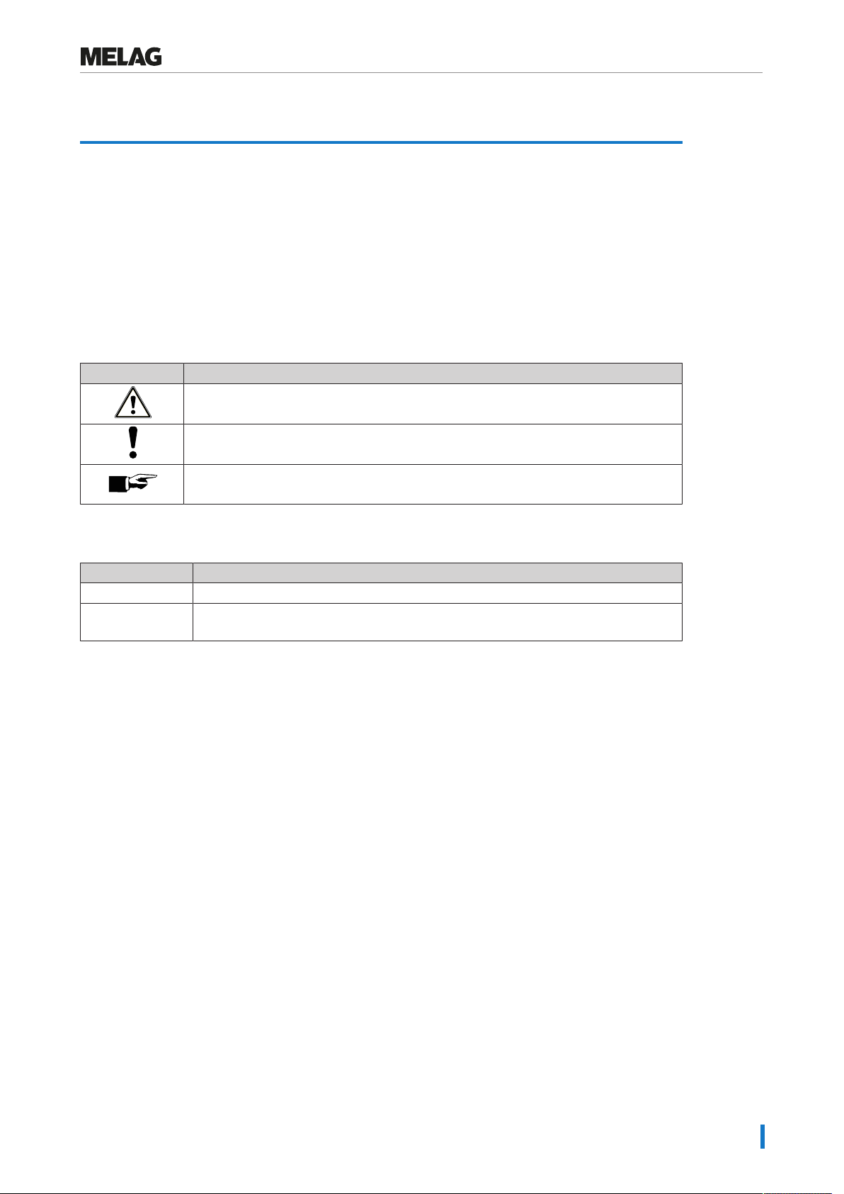
Symbols used.......................................................................................................................................................................5
Formatting rules ...................................................................................................................................................................5
MELAconnect App ...............................................................................................................................................................5
2 Safety.....................................................................................................................................................................................6
3 Description of the device.....................................................................................................................................................7
Intended use ........................................................................................................................................................................7
Scope of delivery..................................................................................................................................................................7
Views of the device ..............................................................................................................................................................8
Symbols on the device.........................................................................................................................................................9
Menu structure ...................................................................................................................................................................10
Status display and acoustic signals ...................................................................................................................................11
4 Commissioning...................................................................................................................................................................12
Requirements of the installation location ...........................................................................................................................12
Space requirements...........................................................................................................................................................12
Connecting the sealing device ...........................................................................................................................................13
Switching on the sealing device.........................................................................................................................................13
5 Sealing.................................................................................................................................................................................14
Sealing procedure with pre-finished film bags ...................................................................................................................14
Sealing procedure for film rolls...........................................................................................................................................15
6 Logging ...............................................................................................................................................................................18
Documenting the sealing process......................................................................................................................................18
Using the USB flash drive as an output medium................................................................................................................18
Computer as output medium..............................................................................................................................................19
Structure of the log files .....................................................................................................................................................19
7 Function tests.....................................................................................................................................................................21
Function test with MELAG Seal Check ..............................................................................................................................21
8 Settings ...............................................................................................................................................................................23
Access settings menu ........................................................................................................................................................23
Time ...................................................................................................................................................................................23
Date....................................................................................................................................................................................24
Sealing temperature...........................................................................................................................................................24
Signal tones .......................................................................................................................................................................25
User administration ............................................................................................................................................................25
Eco Mode and Standby......................................................................................................................................................26
Force calibration.................................................................................................................................................................27
9 Maintenance........................................................................................................................................................................28
Cleaning and regular controls ............................................................................................................................................28
Maintenance.......................................................................................................................................................................28
Validation ...........................................................................................................................................................................28
Software update.................................................................................................................................................................28

Contents
10 Pause times ......................................................................................................................................................................30
Pause times .......................................................................................................................................................................30
Transport and storage........................................................................................................................................................30
11 Optional accessories .......................................................................................................................................................31
Roll dispenser “standard”...................................................................................................................................................31
Roll dispenser “comfort”.....................................................................................................................................................31
Roll dispenser “Deluxe”......................................................................................................................................................32
Wall-mounted roll dispenser...............................................................................................................................................32
12 Malfunctions .....................................................................................................................................................................33
13 Manufacturer's recommendation for routine operation ...............................................................................................35
Performing the peel test.....................................................................................................................................................36
MELAG seal seam stability test .........................................................................................................................................36
14 Standard specifications...................................................................................................................................................37
15 Technical Data ..................................................................................................................................................................39
16 Accessories and spare parts ..........................................................................................................................................40

1 General guidelines
5
1 General guidelines
Read this user manual carefully before commissioning the device. The user manual includes important
safety information. The functionality and value-retention of this device depends on the care accorded to it.
Store this user manual carefully and in close proximity to your device. It represents a component of the
product.
Should the user manual no longer be legible, damaged or lost, obtain a new copy from MELAG. State the
device type and your address in an e-mail.
The device type is specified on the type plate on the rear of the device.
Symbols used
Symbol Explanation
Indicates a dangerous situation, which if not avoided, could entail slight to life-
threatening injuries.
Draws your attention to a situation, which if not avoided, could result in damage to the
instruments, the practice fittings or the device.
Draws your attention to important information.
Formatting rules
Example Explanation
see Chapter 2 Reference to another text section within this document.
Universal-
Program
Words or phrases appearing on the display of the device are marked as display text.
MELAconnect App
The MELAconnect app provides the following functions for MELAG sealing devices integrated in your
practice network from any location in the practice.
▪ Access to user manuals and video tutorials for using the device
▪ Performing quick paperless documentation of routine checks of MELAG sealing devices
▪ Contacting the service technician (contact data must be entered manually)

2 Safety
6
2 Safety
When operating the device, comply with the following safety instructions as well as those
contained in subsequent chapters. Use the device only for the purpose specified in these
instructions. Failure to comply with the safety instructions can result in injury and/or damage to
the device.
Qualified personnel
nOnly competent and trained personnel may use the sealing device.
Set-up, installation and commissioning
nCheck the device after unpacking for any damage suffered during transport.
nThe device is not suitable for operation in explosive atmospheres.
nInstall and operate the device in a frost-free environment.
nThe device is conceived for use outside the patient area. The device should be located a minimum of
1.5m radius away from the treatment area.
Power cable and power plug
nOnly the power cable included in the scope of delivery may be connected to the device.
nThe power cable may not be replaced by a cable determined to be insufficient.
Danger of short circuit
nLiquids may not be permitted to reach the interior of the device. This could result in an electrical shock
or short circuiting.
Repair
nNever open the device housing. Incorrect opening and repair can compromise electrical safety and
pose a danger to the user. The guarantee and warranty are forfeited as soon as the device is opened
by anyone other than a MELAG-authorized technician.

3 Description of the device
7
3 Description of the device
Intended use
This sealing device is designed for application in a medical context, e.g. clinics and medical and dental
practices. It was developed especially for the heat sealing of instruments in sterilization packaging and
complies with the standardENISO11607-2 and the German standard DIN58953-71).
The bar sealing device MELAseal 200 is not a medical device as defined by the Medical Device Regula-
tion.
Suitable materials
It is suitable for the heat sealing of instruments in transparent sterilization packaging in accordance with
DINEN868-5 e.g. MELAfol. Should you wish to use any other packaging materials, please consult your
stockist or contact MELAG directly.
Unsuitable materials
Sterilization packaging that is not compatible with the requirements of DINEN868-5, is incompatible with
this device:
▪ Pure hose film (double-sided film), as these tends to become adhere to the sealing rail, and can restrict
the functionality of the sealing device.
▪ Polyethylene film
▪ Soft PVC film
▪ Hard PVC film
▪ Polyamide film
▪ Polypropylene film
NOTICE
The use of unsuitable packaging materials carries the risk of damage to or malfunction of
the device.
nComply with the manufacturer’s recommendations for the sealing temperatures suitable for
each type of packaging material.
Scope of delivery
Please check the scope of delivery before setting up and connecting the device.
Standard scope of delivery
▪ MELAseal 200 sealing device
▪ User manual
▪ Set up checklist and training protocol
▪ Declaration of conformity
▪ Warranty certificate
▪ Test and calibration protocol
▪ Power cable
▪ Sealing lever
▪ MELAG USB flash drive
1) DIN=Deutsches Institut für Normung

3 Description of the device
8
Views of the device
View from front
1 2
1 Knife handle
2 Display with control lamp
View from rear
3.1 4 3.2
5
3.1 Bracket for roll dispenser
3.2 Bracket for roll dispenser
4 Power cable connection
5 USB port (type B) for connection
to a computer
View from the left
7
6
6 USB port for USB flash drive
7 Square hole for sealing lever
(both sides)

3 Description of the device
9
View from the right
9
10
8
8 Power switch
9 Sealing lever
10 Operating keys
Symbols on the device
Manufacturer of the product
Date of manufacture of the product
SN
Product serial number from the manufacturer
REF
Article number of the product
Electrical connection of the device: AC current
The user manual includes important safety information. Failure to comply with these
instructions can result in injury and material damage.
Please read this user manual carefully before commissioning the device.
In affixing the CE mark, the manufacturer declares that this product fulfils the
corresponding EU requirements.
The device may not be disposed as domestic waste. The vendor is responsible for
appropriate disposal of the device - it must be delivered to the vendor to be disposed of.

3 Description of the device
10
Menu structure
├Standard display output Key
│ └ 180°C/User 1/Ready Temperature/User/Operational readiness
├User User
│ ├ User 01 User 01
│ ├ User 02 User 02
├ ├ User... User...
│ └ User 10 User 10
├Seal chk Function test with MELAG seal check
│ ├ Approve? Performing function test with seal check
│ └ Reminder Activate reminder for seal check
│ ├ weekly weekly
│ │ ├ Mon on Mondays
│ │ ├ Tue on Tuesdays
│ │ ├ … …
│ │ ├ Sun on Sundays
│ ├ daily daily
│ └ Off Deactivate reminder for seal check
├Settings Settings
│ ├ Temp Sealing temperature
│ ├ Tone Switch signal tones on/off
│ ├ Time Time
│ │ ├ Adjust Set current time
│ │ └ Auto_DST Autom. change from summer/winter time (CET)
│ ├ Date Date (TT-MM-JJ)
│ ├ Eco Mode Eco Mode
│ │ ├ On/Off Switch Eco mode on/off
│ │ ├ Wait Eco 1. Waiting time: Setting the Eco Mode
│ │ └ Wait Stby 2. Waiting time: Setting the standby
│ └ Adj Frc Force calibration
└Info Information
├ Seal Cnt Counter for the sealing procedures
├ Svc Date Date of the next service
├ Svc Cnt Counter until the next service
├ Version Software version
└ S/N Serial number
Pressing the keys or repeatedly enables navigation to the ring menu. Pressing returns you
to the next highest menu level.

3 Description of the device
11
Status display and acoustic signals
Control lamp /
acoustic signal
Possible cause Measure
LED illuminates orange
The sealing device is in the
heating or cooling phase.
Wait until the pre-set sealing temperature
has been reached.
LED flashes red,
warning signal sounds
The sealing lever is depressed
during the heating phase.
The sealing temperature has not
yet been reached.
The sealing lever has been raised
early, despite the required sealing
duration not having been reached.
The sealing lever has not been
raised, despite the required
sealing duration having been
completed.
Acknowledge the display message with
OK
and wait until the LED control lamp is
continuously illuminated green.
Acknowledge the display message with
OK
and leave the sealing lever depressed
during sealing until the message Open is
issued.
Raise the sealing lever as soon as the
display message Open is issued, otherwise
the sealing procedure is unsuccessful.
Failure to comply with these provisions can
result in the melting of the film and damage
to the sealing device.
LED illuminates green
The sealing device has reached
the pre-set sealing temperature
and is ready for operation.
The minimum sealing duration has
been reached and the sealing
procedure has been ended.
Raise the sealing lever and remove the
packaging.
LED flashes green
The sealing procedure runs when
the sealing lever is depressed; the
progress bar is displayed.
Wait until the green LED control lamp is
continuously illuminated or the display
shows Open.
LED illuminates red,
warning signal sounds
(malfunction)
Device malfunction: The heating
phase is taking too long (>5min);
the sealing device does not reach
the pre-set sealing temperature.
Switch off the sealing device and then on
again. Upon repeated incidence, contact an
authorized customer services or stockist
technician.

4 Commissioning
12
4 Commissioning
See also “Installation and Set-up”.
Video tutorial
Requirements of the installation location
CAUTION
Failure to comply with the set-up conditions can result in injuries, malfunctions and/or
damage to the device.
nComply with all the specifications of this chapter for initial commissioning.
uThe device is not suitable for operation in explosive atmospheres.
uThe device is only intended for use in interior spaces.
uThe device is conceived for use outside the patient area. The device should be located a minimum of
1.5m radius away from the treatment area.
uInstall the device in a dry and dust-protected location.
uMaintain sufficient clearance to the surrounding surfaces in order to ensure sufficient ventilation.
uEnsure that the sealing device is located away from direct sunshine and outside the range of other
sources of heat.
uSet-up the device protected against blows or vibrations.
Space requirements
Fig.1: View from the front and right
Dimensions MELAseal 200
Width A 36.5 cm
Width including lever A141.5 cm
Height B 15 cm
Minimum clearance above B125 cm
Minimum clearance to the side C 10 cm
Minimum clearance to rear C18 cm
Depth D 24 cm
When using film rolls, additional space is required for a roll dispenser e.g. the “standard” or “Deluxe”
models.

4 Commissioning
13
Connecting the sealing device
ü
The sealing device has been switched off.
ü
Use the power cable included in the scope of delivery.
1. Connect the rubber connector of the power cable to
the rear side of the sealing device and connect the
power plug in the mains socket.
2. Insert the sealing lever in the square hole on the right
or left hand side of the device as required.
Switching on the sealing device
ü
The sealing device is connected to the power supply.
ü
The USB flash drive is connected for documentation purposes.
}Switch on the sealing device at the power switch.
ÊAfter activation, the display issues system information e.g. the user set, confirmation as to whether the
USB flash drive is connected correctly and the current temperature.
ÊThe control lamp on the front of the sealing device illuminates orange and the sealing device is heated
to the pre-set temperature.
Operational Readiness
The sealing device is ready for operation as soon as the pre-set sealing temperature has been reached,
the display shows Ready and the control lamp illuminates continuously green.

5 Sealing
14
5 Sealing
See also “Wrapping Instruments”.
Video tutorial
Sealing procedure with pre-finished film bags
CAUTION
Danger of burns from hot metal parts. The sealing rail is heated continuously when the
sealing device is switched on.
nNever touch the metal surfaces on the sealing rail and in the area of the rear and fore paper
guide directly.
NOTICE
Inserting the packaging inverted can result in the adhesion of film residue to the sealing
rail.
The film side of the packaging must always face upwards.
PLEASE NOTE
When sealing MELAfol bags with a side gusset, ensure compliance with the
manufacturer’s specifications (e.g. the operating manual of MELAfol) especially when
wishing to seal cassettes.
In order to perform a sealing procedure with a prefabricated film bag, proceed as follows:
1. Lead the packaging (the film side facing upwards)
from the front into the paper guide between the
pressure and sealing rail. Ensure maintenance of the
correct clearance between the instrument and seal
seam (see Standard specifications [}page37]).
2. Press the sealing lever down until it latches.

5 Sealing
15
3. Leave the sealing lever depressed as long as the
progress bar in the display completes and the control
lamp flashes green at short intervals (approx. 3s).
4. If the display switches to Open and the control lamp is
continuously illuminated green, return the sealing
lever upwards to its starting position.
ÊIf the USB flash drive has been connected, a log
will automatically be generated and saved on
the USB flash drive.
ÊIf a USB flash drive has not been connected, the
most important sealing parameters will be
displayed alternately up to four times. Then the
display changes to Ready.
5. Perform a visual inspection of the film after every
successful sealing procedure.
PLEASE NOTE
With bags with side gussets, perform weekly controls of the seal seam using an ink test
(e.g. MELAink test).
Sealing procedure for film rolls
Produce film bag
To package instruments in transparent sterilization packaging bags from the roll, proceed as follows:
1. Guide the end of the film roll along the device rear
panel into the lower paper guide with the paper side
facing downwards (lower slit). Slide the film forwards
and between the pressure and sealing rail to the
desired length.

5 Sealing
16
2. Press the sealing lever down until it latches.
3. Leave the sealing lever depressed as long as the
progress bar in the display completes and the control
lamp flashes green at short intervals (approx. 3s).
4. Cut of the film roll during the sealing procedure. To
this end, leave the sealing lever depressed and move
the handle of the knife to the other end of the sealing
device quickly. Do not return the knife handle.
5. If the display switches to Open and the control lamp
illuminates continuously green, raise the sealing lever
again and remove the film bag from the sealing
device.
Sealing film bags
NOTICE
Inserting the packaging inverted can result in the adhesion of film residue to the sealing
rail.
The film side of the packaging must always face upwards.
To seal the film bag cut to the corresponding length, proceed as follows:
1. Place the instruments to be sterilized in the film bag.
Ensure maintenance of the correct clearance between
the instrument and seal seam (see Standard
specifications [}page37]).

5 Sealing
17
2. Slide the open side of the film bag into the paper
guide from the front.
3. Press the sealing lever down until it latches.
4. Leave the sealing lever depressed as long as the
progress bar in the display completes and the control
lamp flashes green at short intervals (approx. 3s).
5. If the display switches to Open and the control lamp is
continuously illuminated green, return the sealing
lever upwards to its starting position.
ÊIf the USB flash drive has been connected, a log
will automatically be generated and saved on
the USB flash drive.
ÊIf a USB flash drive has not been connected, the
most important sealing parameters will be
displayed alternately up to four times. Then the
display changes to Ready.
6. Perform a visual inspection of the film after every
successful sealing procedure.

6 Logging
18
6 Logging
Documenting the sealing process
See also “Documentation and User Administration”.
Video tutorial
ENISO11607-2 requires that the sealing procedure be monitored and documented in order to demon-
strate that it corresponds with the requirements of part2 of the standard. As a result, you are able to re-
cord the logs of the seal runs, output them on the following output media and archive them accordingly:
▪ USB flash drive
▪ Computer with documentation software e.g. MELAview/MELAtrace from software version 3.6
If a computer or USB stick is not connected, the most important sealing parameters can also be
documented by hand. The sealing parameters are displayed alternately up to four times.
Using the USB flash drive as an output medium
NOTICE
Danger of data loss through damage of the USB flash drive following improper use.
nDo not exert any force on the USB flash drive whilst inserting it.
nDo not place any objects on the inserted USB flash drive.
A USB flash drive will be delivered with every sealing device as standard. Should you wish to save the log
of a sealing procedure on the USB flash drive automatically, connect it as follows:
1. Switch off the sealing device.
2. Insert the USB flash drive in the USB interface on the
left-hand side of the sealing device.
3. Switch on the USB flash drive.
ÊAs soon as the USB flash drive has been recognized and is ready for operation, the display will show
Mem_Conn (=memory connected).
Comply with the following general information relating to logging with the USB flash drive:
uAlways switch off the sealing device before connecting or removing the USB flash drive.
uIf the USB flash drive has been reformatted, it must be issued with a name.
uCopy the log files from the USB flash drive to the computer at regular intervals.
uSelect only a single logging type, either by USB flash drive or via MELAtrace/MELAview. Otherwise,
this can result in a failure to recognize that the output media has been disconnected, which can result
in data loss.
uDo not save any further non device-relevant files on the USB flash drive.

6 Logging
19
Computer as output medium
The following conditions must be fulfilled in order to use the computer as an output medium:
ü
The computer is equipped with an USB port.
ü
The MELAG USB driver is installed on the computer.
ü
The sealing device is connected to the computer via a USB cable (optionally available).
ü
Firmware 1.12 requires MELAview Doku/MELAtrace version 3.0.15.1.
ü
Firmware 2.10 and above requires MELAview Doku/MELAtrace from version 3.6.2.1.
1. Install the MELAseal 200 PC driver on your computer.
The driver can be downloaded from the MELAG
website (Service/Download Center).
2. Connect the type B USB cable to the rear panel of
the sealing device and connect the other end to the
computer.
3. Establish a connection between the documentation
software and the sealing device and determine the
folder in which the sealing logs are to be archived.
Further information relating to the operation of the
sealing device with the documentation software can
be found in the corresponding operating manual.
PLEASE NOTE
The daily log is continued even if the sealing device is switched on and off once; i.e. a
new daily log is not started.
Structure of the log files
The log is stored in HTML format (in English). The file name consists of the actual date, the serial number
of the sealing device and the total counter. A log includes all printing procedures of one day. A row in the
log is written for every sealing procedure.
20130723_132000901_0000095.htm
Date Serial number Total counter
A successful sealing procedure is marked with “OK” in the respective log row. If a malfunction occurs dur-
ing a sealing procedure, this is recorded in the log by a incident number, e.g. F4. The corresponding fault
value (e.g. sealing temperature, or force) will, depending on the nature of the malfunction, be displayed in
square brackets or no value will be displayed.

6 Logging
20
Example of a log of multiple sealing procedures
Key:
Row 10 – Description of the sealing device
Row 15 – Date of sealing procedure
Row 20 – Serial number of the sealing device
Row 25 – Installed software version
Row 30 – Total operating hours
Row 35 – Date of the next maintenance
---------- --------------
Stat – OK: Sealing procedure successful
– Err_F03: Malfunction number/sealing duration too short
Time – Time of the sealing procedure
Dur – Sealing duration
Temp – Sealing temperature (in °C)
Force – The force (in N), with which the packaging was sealed
Limits – The threshold ranges of the sealing duration (Dur), sealing temperature (Temp) and force
(Force)
Usr – User
SCnt – Daily batch counter for sealing procedures
SvcCnt – Number of sealing procedures until next maintenance
TtlCnt – Total number of the sealing procedures
CS – Coded proof of authenticity
S/N – Serial number of the sealing device
Op. Hrs. – Total of previous operating hours
Other manuals for MELAseal 200
3
Table of contents
Other MELAG Kitchen Appliance manuals