MELAG MELAprint 80 User manual

User Manual
MELAprint 80
Universal printer
EN
Dear customer,
We thank you for your confidence demonstrated by the purchase of this MELAG product. As an owner-run and operated
family concern founded in 1951, we have a long history of successful specialization in hygiene products for practice-
based use. Our focus on innovation, quality and the highest standards of operational reliability has established MELAG
as the world’s leading manufacturer in the instrument reprocessing and hygiene field.
You, our customer are justified in your demand for the best products, quality and reliability. Providing “competence in
hygiene” and “Quality – made in Germany”, we guarantee that these demands will be met. Our certified quality
management system is subject to close monitoring: one instrument to this end is our annual multi-day audit conducted in
accordance with ENISO13485. This guarantees that all MELAG products are manufactured and tested in accordance
with strict quality criteria.
The MELAG management and team.


Contents
Contents
1 General guidelines ...............................................................................................................................................................4
Symbols used ......................................................................................................................................................................4
Formatting rules...................................................................................................................................................................4
Symbols on the device.........................................................................................................................................................4
Disposal ...............................................................................................................................................................................5
2 Safety.....................................................................................................................................................................................6
3 Description of the device.....................................................................................................................................................7
Scope of delivery .................................................................................................................................................................7
Intended use ........................................................................................................................................................................7
Compatibility with MELAG products ....................................................................................................................................7
Views of the device..............................................................................................................................................................8
4 Commissioning...................................................................................................................................................................11
Loading printing material ...................................................................................................................................................11
Switching on the printer .....................................................................................................................................................14
Automatic detection of material length...............................................................................................................................15
Setting up the printer at the steam sterilizer ......................................................................................................................15
Reading out the printer configuration (print self-test).........................................................................................................20
Daily operation...................................................................................................................................................................20
5 Troubleshooting .................................................................................................................................................................21
General malfunctions.........................................................................................................................................................21
LED status .........................................................................................................................................................................22
6 Maintenance........................................................................................................................................................................23
Routine maintenance.........................................................................................................................................................23
Replacing the print head....................................................................................................................................................24
7 Technical data ....................................................................................................................................................................26
8 Accessories ........................................................................................................................................................................27

1 General guidelines
4
1 General guidelines
Please read this user manual carefully before commissioning the device. The user manual includes important safety
information. The functionality and value-retention of this device depends on the care accorded to it. Please store this
user manual carefully and in close proximity to your device. It represents a component of the product.
The device type is specified on the type plate on the lower side of the device.
Should the manual no longer be legible, is damaged or has been lost, you can download a new copy from MELAG
download centre at www.melag.com.
Symbols used
Symbol Description
Draws your attention to a situation, which if not avoided, could result in damage to the prac-
tice fittings or the device.
Draws your attention to important information.
Formatting rules
Example Description
Settings Reference to a menu command, window title or a button.
see Chapter 2 Reference to another text section within this document.
Reference to the glossary or another text section.
Information for safe handling.
Prerequisites for the following handling instruction.
Symbols on the device
Type plate
Do not dispose of product in household waste
CE marking
Warning symbols
The marked area becomes hot during operation. Contact with it during or shortly after operation can
pose the danger of burns.
Symbols on the power switch
Switching on device
Switching off device

1 General guidelines
5
Disposal
MELAG devices are synonymous with high quality and a long life-span. When you eventually need to decommission your
MELAG device, the required disposal of the device can take place with MELAG in Berlin. Simply contact your stockist.
Dispose of accessories and consumption media which you no longer require in the appropriate manner. Comply with all
relevant disposal specification in terms of possibly contaminated waste.
The packaging protects the device against transport damage. The packaging materials have been selected for their
environmentally-friendly disposability and can be recycled. Returning the packaging to the material flow reduces the
amount of waste and saves raw materials.
MELAG draws the operator’s attention to the fact that they may be legally obliged (e.g. in Germany according to
ElektroG) to remove used batteries and accumulators non-destructively before handing over the device, provided they
are not enclosed in the device.

2 Safety
6
2 Safety
When operating the device, comply with the following safety instructions as well as those contained in
subsequent chapters.
Power cable and power plug
nOnly the power cable included in the scope of delivery may be connected to the device.
nThe power cable may not be replaced by a cable determined to be insufficient.
nDisconnect the device from the mains during long downtimes.
nOnly connect the device to those products intended for operation with this device.
nOnly connect the device to a suitable power source.
Danger of short circuit
nLiquids may not be permitted to reach the interior of the device. This could result in an electrical shock or short
circuiting.
Setup, installation and commissioning
nCheck the device after unpacking for any damage suffered during transport.
nThe device is not suitable for operation in explosive atmospheres.
nInstall and operate the device in a frost-free environment.
nThe device is conceived for use outside the patient area. The device should be located a minimum of 1.5m radius
away from the treatment area.
Installation location and storage
nSetup the device on a stable, level surface.
nSetup the device in such a way that it is protected against strong direct sunlight and heat.
nStore and operate the device only in a dust-free environment protected against heat and damp.
nDo not place the device directly on the steam sterilizer. The steam sterilizer will become hot upon operation. Non-
compliance could result in restricted function and damage to the device.
nSet-up the device protected against blows or vibrations.
Daily operation
nAlways check whether a material roll has been inserted before printing. Otherwise, the print head and print roller
could suffer damage.
nNever touch the blade of the device.
nNever touch the print head during or shortly after operation, as this can be very hot.
nThe print head of the device is an sensitive component. Do not touch the print head so as not to damage it.
Maintenance
nAlways allow the device to dry after cleaning before closing the housing cover.
Repair
nNever open the device housing. Incorrect opening and repair can compromise electrical safety and pose a danger to
the user.
nThe device may only be opened and repaired by authorised technicians. The guarantee and warranty are forfeited
as soon as the device is opened by anyone other than a member of a MELAG-authorised technical customer
service.

3 Description of the device
7
3 Description of the device
Scope of delivery
Please check the scope of delivery before setting up and connecting the device.
Standard scope of delivery
▪ MELAprint80
▪ User documentation card
▪ Power cable
▪ Power supply
▪ Ethernet cable 1:1 (RJ45)
▪ USB cable
▪ Label roll, double-sided
Intended use
The MELAprint80 printer serves the direct output of labels and logs for MELAG devices or via the documentation and
approval software MELAtrace; it may only be used by trained practice or IT personnel. The labels for sterilization
wrapping can then be read-out with a barcode scanner (not included in the scope of delivery).
Compatibility with MELAG products
Category Device class Device type
Software Documentation and approval software MELAtrace
Combi devices Combi steam sterilizers Careclave 6181)
Steam sterilizers Vacuclave Vacuclave 5502)
Pro Line Vacuclave 1183)
Vacuclave 1233)
Prime Line Vacuclave 3183)
Vacuclave 3233)
SteriHero Line SteriHero Beauty3)
SteriHero Vet3)
Pro-Class Vacuklav 23 B+4)
Vacuklav 31 B+4)
Vacuklav 24 B+4)
Vacuklav 24 BL+4)
Vacuklav 30 B+4)
Vacuvet Vacuvet 23 B+4)
DAC DAC Professional4)
Euroklav Euroklav 29 VS+4)
Euroklav 23 VS+4)
Euroklav 23 S+4)
MELAtronic EN/EN+ MELAtronic 23 EN4)
MELAtronic 15 EN+4)
MELAquick MELAquick 12+/12+ p4)
3 Description of the device
8
1) Label printing only; from software version v22.0.3
2) Label printing only; from software version v4.0.1
3) Label printing only; from software version v2.3.1;
Log printing; from software version v2.6.1
4) Log printing only; from software version v5.21
Views of the device
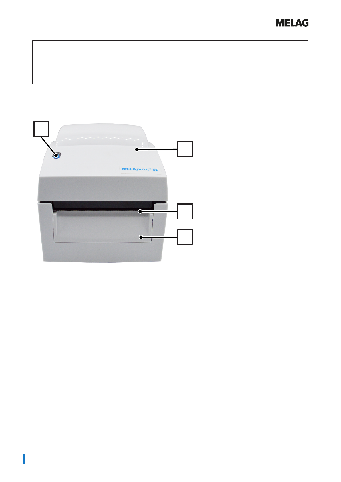
Front view of the device
1
3
2
4
1 FEED button with LED
2 Housing cover
3 Tear-off edge
4 Front cover
3 Description of the device
9
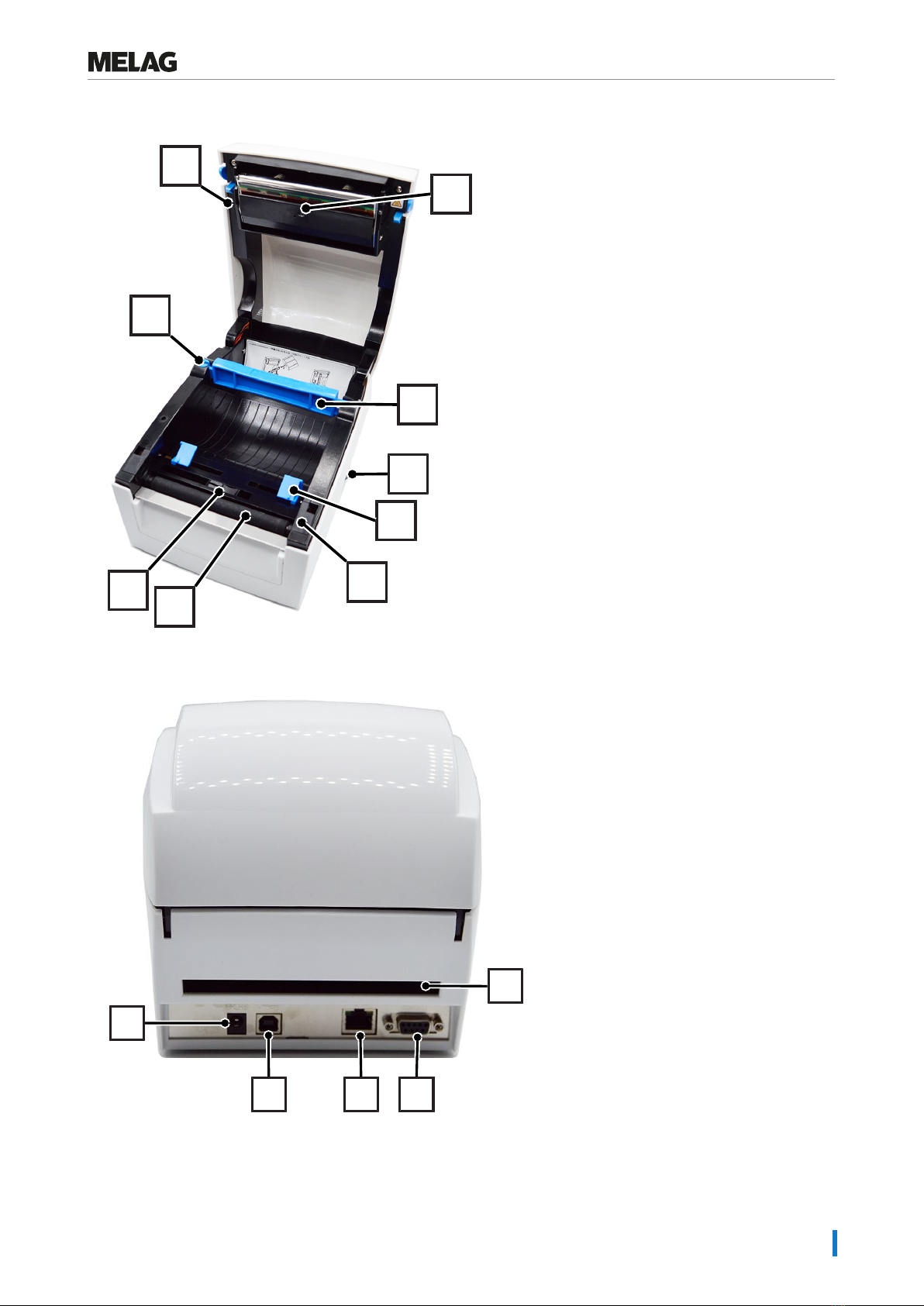
Interior view of the device
5
6
7
8
10
13 11
12
9
5 Reel dispenser
6 Print head lever
7 Print mechanism with print head
8 Roll core
9 Power switch (ON/OFF)
10 Material guidance
11 Roller cover
12 Printer roller
13 Sensor
Rear view of the device
14
18 17 16
15
14 Power cable connection
15 Continuous paper feeder
16 Serial interface (RS-232)
17 Ethernet interface (RJ45)
18 USB interface

3 Description of the device
10
FEED button
After pressing the FEED button, the printer moves the label to the specified stop position. If the label does not stop at the
correct position, the label material must be calibrated, see Automatic detection of material length [}Page15]. For log
printing: When printing with continuous media, pressing the FEED button will advance the material until you release the
FEED button.
LED
There is an LED on the FEED button that indicates the operating status of the printer.
The following statuses are possible:
LED Status Description
green Standby mode Printer is ready for operation
red (flashing) Error mode Printer in error
Other manuals for MELAprint 80
1
Table of contents
Other MELAG Printer manuals


