mensor 9414 User manual

Mensor Model 9414 Multi-Channel Pressure Controller 0017964001A
9/13/12 Mensor LP, 201 Barnes Drive, San Marcos, TX, USA
Multi-Channel Pressure Controller
Mensor Model 9414
Operation Manual - PN 0017964001


Mensor Model 9414 Multi-Channel Pressure Controller 0017964001A 9/13/12
1
Mensor Model 9414
Multi-Channel Pressure Controller
Software Version 2.00
General Description:
The Mensor Model 9414 Multi-
Channel Pressure Controller is
typically part of the Mensor
9415 Multi-Channel Test
System. This test system is a
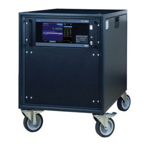
mobile pressure rack
configured with either one four
channel Model 9414 Quad
Pressure Controller with four Mensor digital pressure transducers and two 9412
dual tank modules or one two channel Model 9414 Dual Pressure Controller with
two Mensor digital pressure transducers and one 9412 dual tank module.
Auxiliary equipment provided in the system usually includes a pressure booster,
venturi vacuum generator, related automated electrical and pneumatic switching
devices and an external remote transducer selection and readout module. As
such, the standalone 9414 has many features that are designed to work with the
complete test system.
The 9414 standalone unit is a two or four channel pressure controller that is
optimized for controlling large volumes and constantly replenishing small
amounts of air a rapid rate. The unit requires universal AC power (90 to 260
VAC, 50 or 60 Hz.) brought in through the rear panel IEC-320 power input
module, two pressure supply ports for supply pressure and two vacuum input
ports to supply vacuum if sub-atmospheric pressure output is required. The unit
has separate control output ports and measure input ports for each channel.
Any external or remote transducers communicate with the 9414 over an RS-485
communications port found on the rear panel. Control of up to 8 solenoids
valves (12vdc at a maximum of 1 amp) can be done with the 9414 controller and
is provided to the user through the same 25 pin D-sub connector containing the
RS-485 signals. The RS-485 port operates at 19200 Baud with 8 data bits, 1
stop bit, and no parity. External transducers must be addressed as 1, 2, 3, 4 or
5.
Communications between the Model 9414 Quad Pressure Controller and the
user’s computer are on an RS-232 9 pin D-Sub connector at 57,600 Baud, 8 data
bits, 1 stop bit and no parity. The command set is provided in this manual.
Precautions:

Mensor Model 9414 Multi-Channel Pressure Controller 0017964001A 9/13/12
2
1. The system has a maximum working pressure of up to 300 psi (~2068
kPa).
2. The system can drive large pressure storage tanks that can hold large
amounts of kinetic energy. User should bleed all pressure stored in the
tanks before servicing, removing pressure hoses, or removing
instruments. Normal shutdown and emergency shutdown should start the
process, but due to the size of the tanks and desire to maintain a safe
discharge rate, this operation may take an extended period of time to
achieve. Utilize the pressure gauges on the front of the 9412 if so equiped
to insure pressure has been released from each tank.
3. The system uses normal power line AC voltages. User should remove
the AC power cord from mains when servicing inside enclosures.
4. Due to the internal pressures and voltages used within the 9415
system, only qualified and properly trained personnel should service this
system.
5. The emergency shutdown electrical system is limited in capacity to
approximately 6 amps of power. It is intended to shut down the pressure
portion of the system (Model 9414).
Setup:
The initial installation should include removing any packing material used in
shipment and inspect that fittings and screws are snug, and that hoses and
electrical cords are not chaffed or cut. The system should be installed on a level
surface with adequate airflow to keep the system within its 15 to 45 C optimum
operating temperature range. The system operates on line voltages between 90
and 260 VAC, 47 to 63 Hz. A dry compressed air supply is required for
operation. This supply should be approximately 110 % of the 9414 maximum
range. The air supply should be a quality class of 5 or better. This limits dirt
particles to less than 40 microns, a water pressure dew point of 45 F or lower at
100 psig, and oil vapor of less than 25 ppm. Two supply pressure ports are
provided on the rear of the unit. One is for channels P1 and P2, and the other is
for channels P3 and P4. If sub-atmospheric pressures are required, the two
exhaust ports on the rear will accept exhaust pressures from a suitable vacuum
pump. Of these two fittings on the rear, one is for exhaust of channels P1 and
P2 and the other is for channels P3 and P4.
The quad pressure control output ports are located on the rear of the 9414 and
are labeled P1, P2, P3 and P4 Control. Pressure input ports are also in the
upper left quarter of the rear panel and are labeled P1, P2, P3 and P4 Measure.

Mensor Model 9414 Multi-Channel Pressure Controller 0017964001A 9/13/12
3
If a dual channel system is ordered, only P1 and P2 will be available. These
manifold ports are 7/16-20 straight thread and accept adapters for most common
fittings, ¼” tube, 6mm tube, 1/8 Female NPT, etc.
Operation:
Generally, the system once configured requires power, clean dry air or nitrogen,
and possibly a vacuum source. Start up operation commences when power is
applied.
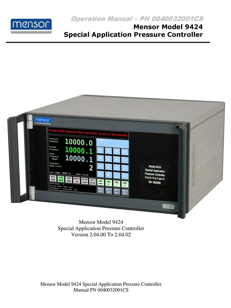
Operation of Model 9414
The 9414 was designed for
predominately remote operation,
but can be operated in most
instances from the front panel
through the LCD touch screen
interface.
On power up, the unit will
initialize with all channels in the
measure mode. All solenoid
valves will be in their de-
energized state.
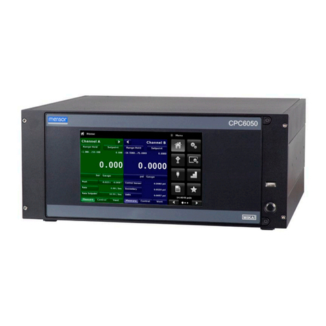
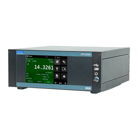
The front panel display is divided
into four main areas. Across the
top of the LCD the model number and instrument description is displayed. On
the left side of the display below the model number is the main controller area.
Space is provided in this area to display the channel setpoint, the actual pressure
reading and the mode of operation for each of the four channels. If the 9414 is
populated with only two channels, the bottom two areas will be blank. In the
lower right corner is a status window. This window displays the units of measure,
a button to display and change the status of the VACuum enable solenoid valve
(if equipped), a button to display and change the status of the AIR supply enable
solenoid valves(if equipped), a window to display the number of remote
transducers (Addresses 1, 2, 3, 4 or 5) found during the power up query and a
window indicating the control status of P1, P2, P3 and P4. A P-OK status of
green indicates the controller is within the allowed tolerance window of the
control setpoint. A red square indicates that the controller is out of the tolerance
window. The window should be green in all other operating modes, (MEAS,
VENT, and STBY). The forth window is dynamic and changes based on the
process state. Typically it displays the reading of any remote transducers found

Mensor Model 9414 Multi-Channel Pressure Controller 0017964001A 9/13/12
4
during initial power up. If one of the four setpoints is being edited, the remote
transducer window will become a keypad for entering new values or control
points into the selected channel. Once the setpoint is entered (by pressing the
‘=’ button) the window will revert back to displaying the remote transducer
readings. If the mode of operation is being edited, this window will allow the
mode selection of measure, control, vent or standby. Once the mode has been
selected, the window will revert back to displaying the remote transducer
readings.
To change a setpoint, touch over the current setpoint value for the desired
channel (P1, P2, P3, or P4) and the keypad menu will appear on the right. Press
the keys for the new value and than end by pressing the equal key ('=‘) to enter
the value. The new value should appear in the setpoint window. Values that are
outside of the control range will not be accepted and the user must again touch
over the current setpoint value and re-enter a valid pressure. Note: it is possible
to enter a value up to a maximum of 300 psi (2088 kPa). It is the user’s
responsibility to insure attached devices can handle the full pressure.
To change the mode of operation for a channel, touch the current displayed
mode for the particular channel (P1, P2, P3 or P4). Four buttons will be
displayed to the right allowing the modes of measure (MEAS), control (CTRL),
vent (VENT) or standby (STBY) to be selected. Once the mode has been
pressed, the mode will be changed on the control screen and the remote
transducer readings will be re-displayed.
A typical start process should include the following steps:
1. Turn Power ON using the rear panel power switch. If the EMERGENCY
SHUTOFF button has been pressed, this should be rotated clockwise to
disengage. The normally open vent valves will automatically close. The system
will interrogate the 9414 for installed control channels. This will typically be either
two or four. The system will than check for remote transducers. The system can
have one to four attached transducers. Internal transducers found will be
displayed in the main control screen with its setpoint, reading and mode. If no
internal transducer is found for a particular channel, the setpoint, reading and
mode will be blank. Remote transducers will be displayed in the lower right
status window under REMOTE as 1, 2, 3, 4 and B. The reading will also be
displayed in the remote transducer reading window on the right side of the
screen. Remote transducers are addressed as 1, 2, 3, and 4. If a barometric
transducer is included in the system, this will be addressed as 5, but will be
displayed on the status window as ‘B’ for barometer.
2. Provide the vacuum source to the system if required.
3. Provided appropriate source pressure to the system.
4. Before placing a channel in the control mode, verify that the system has no
open hoses and that connections are verified to be leak free.

Mensor Model 9414 Multi-Channel Pressure Controller 0017964001A 9/13/12
5
5. The channels that are going to be used in the control mode should have their
setpoints entered.
6. Once the setpoints are entered, the channel mode should be set to control.
The channel will drive to the setpoint. Once within the setpoint window, the P-
OK status window will change from red to green. The orientation of the four
status squares matches the main window. P1 is in the upper left, P2 in the upper
right, P3 in the lower left, and P4 in the lower right. Failure to achieve a green
status can be caused by a pressure leak, or because of insufficient source
pressure. The time it takes to reach an initial setpoint is mainly determined by
the size of the internal storage tanks, but can also depend on the source
pressure capacity and the delta pressure change.
Communication Protocol:
Communications between the user’s external computer and the 9414 System
Control Module is standard RS-232 serial communications with a protocol of
57600 baud, 8 data bits, 1 stop bit and no parity. The 9414 will accept both
upper and lower case ASCII commands. A complete command set can be found
below.
Communications between the 9414 controller and any external transducers is full
duplex RS-485 serial communications with a protocol of 19200 baud, 8 data bits,
1 stop bit and no parity. These RS485 communications along with the 8 solenoid
drive signals can be found on the 25 pin D-Sub located on the rear of the 9414.
The 9414 handles all communication with the transducer(s) inside the module as
well as provide the 12 volt DC power to the external transducer(s) and solenoid
valves when present. To calibrate the Mensor 6100 transducer(s) inside the
Remote Transducer Module use the 6180 command set described in the Series
6180 User’s Manual. A copy of the manual can be found in the appendix of this
document. It is usually best to remove the transducers from the 9414enclosure
and calibrate them as standard
Command Set:
All commands should terminate with a linefeed. Carriage Returns are ignored on
incoming commands and should be avoided to reduce communication traffic.
Responses are terminated with a carriage return followed by a linefeed.
Commands are accepted in either uppercase or lowercase characters. Protocol
is set at 57,600 baud, 8 data bits, 1 stop bit, no parity. Communication is RS-232
on a 9 pin D-sub.
The Model 9414 Quad Controller has a color LCD touch screen display that allow
setting of control pressures, monitoring of controller readings and remote
transducer readings. Front panel touch screen operation can be locked out

Mensor Model 9414 Multi-Channel Pressure Controller 0017964001A 9/13/12
6
using commands over the communications port. (See PanelLock and
PanelUnlock commands below.)
The following command set is an extension of the older Model 9411 System
Controller. Where applicable, this command set is maintained in the 9414
System Controller/ Quad Pressure Controller. Model 9411 commands that have
limited use in the 9414 based system are highlighted in gray. The user should
determine if the commands highlighted in gray are necessary based on initial
configuration and the overall system configuration.
Command
Description
Example
vacpump?
Returns status of vacuum
pump valve as either
enabled or disabled.
Returns
‘Pump Off’ or
‘Pump Enabled’
Or ‘Function not
available ‘
Vacpumpenable
Energizes vacuum pump
valve to enable sub
atmospheric pressures to
upper APC600 controller.
Responds with 'Pump
Enabled'
Returns
‘Pump Enabled’
Or ‘Function not
available ‘
Vacpumpsafe
De-energizes vacuum pump
valve to shutoff vacuum and
vent exhaust port of upper
APC600 controller.
Responds with ' Pump Off'
Returns
‘Pump Off’
Or ‘Function not
available ‘
Status?
Returns the status of the
sixteen solenoid valves drive
signals. A '1' indicates
enabled, and a '0' indicates
disabled. The solenoids are
labeled from left to right as
S1 to S16.
On Model 9414 units only
the 8 external solenoid
valves are shown. The
solenoids are labeled from
left to right as S1 to S8.
Returns:
1001000000000000
Indicates that valves
one and 4 are
energized and all
others are de-
energized.
Returns:
11001010
Indicating valves 1,
2, 5 and 7 are
enabled.
Supply?
Returns status of supply
valve as either enabled or
disabled
Returns
'Supply Enabled' or
'Supply Off'
Or ‘Function not
available ‘

Mensor Model 9414 Multi-Channel Pressure Controller 0017964001A 9/13/12
7
Supplyactive
Energizes pressure supply
valve to enable shop air
supply to the pressure
booster and ultimately to the
pressure controllers
Returns
‘Supply Enabled’
Or ‘Function not
available ‘
Supplysafe
De-energizes pressure
supply valve to shutoff
supply to pressure
controllers and pressure
booster. Vents the supply
lines.
Returns
‘Supply Off’
Or ‘Function not
available ‘
x1?
Returns pressure reading
from transducer 1, the
highest range Mensor 6100
remote transducer.
Returns 8 character
value string in the
current pressure
units, or 0 if not
transducer attached.
x2?
Returns pressure reading
from transducer 2, a higher
range Mensor 6100 remote
transducer.
Returns 8 character
value string in the
current pressure
units
or 0 if not transducer
attached.
x3?
Returns pressure reading
from transducer 3, a lower
range Mensor 6100 remote
transducer.
Returns 8 character
value string in the
current pressure
units
or 0 if not transducer
attached.
x4?
Returns pressure reading
from transducer 4, a lower
range Mensor 6100 remote
transducer.
Returns 8 character
value string in the
current pressure
units
or 0 if not transducer
attached.
xhi?
Returns pressure reading
from both high pressure
transducers (x1 and x2)
Returns two sets of 8
character values with
3 fractional digits
separated with a
comma and space.
Reading 1 is first and
reading 2 is second.
or 0 if not transducer
attached.
xlo?
Returns pressure reading
from both low pressure
transducers (x3 and x4)
Returns two sets of 8
character values with
3 fractional digits

Mensor Model 9414 Multi-Channel Pressure Controller 0017964001A 9/13/12
8
separated with a
comma and space.
Reading 3 is first and
reading 4 is second.
or 0 if not transducer
attached.
Xbaro?
Returns the pressure
reading of the barometric
reference transducer if
installed in system.
Reading or 0 if not
transducer attached.
X5?
Returns the pressure
reading of the barometric
reference transducer if
installed in system.
Reading or 0 if not
transducer attached.
xall?
Returns pressure reading
from all four pressure
transducers (1, 2, 3 and 4)
and the barometric
reference transducer if
installed.
Returns 4 sets of 8
character values with
3 fractional digits
separated by a
comma and space.
Reading 1 is first
followed by readings
2, 3 and 4 and than
the barometric
reference if installed.
serialno?
Returns the serial number of
the control module
Returns the system
control module serial
number of
‘990194’
s4on
Energizes solenoid 4 (V4)
s4off
De-energizes solenoid 4
s5on
Energizes solenoid 5 (V5)
s5off
De-energizes solenoid 5
s6on
Energizes solenoid 6 (V6)
s6off
De-energizes solenoid 6
s7on
Energizes solenoid 7 (V7)
s7off
De-energizes solenoid 7
s10on
Energizes solenoid 10
s10off
De-energizes solenoid 10
s12on
Energizes solenoid 12
s12off
De-energizes solenoid 12
s14on
Energizes solenoid 14
s14off
De-energizes solenoid 14
s16on
Energizes solenoid 16
s16off
De-energizes solenoid 16
ventall
Turns off regulators and
places channels in vent

Mensor Model 9414 Multi-Channel Pressure Controller 0017964001A 9/13/12
9
mode
id?
Returns the system
identification string
Returns:
‘Mensor 9414 Quad
Controller , SN:
990194’
Shutdown
De-energizes all solenoid
valves allowing any air
trapped in the tanks to be
slowly released. Incoming
pressure and vacuum is
shut off and any trapped
source pressure is released.
Places controller in measure
mode.
Commands set of the pressure controller portion of the 9414
SetP1=
Enters the control pressure
setpoint for P1 in the current
units of measurement. Must
be between the minimum
and maximum pressure
range of the system.
Typically 0 to 300 psia or
approximately 0 to 2068
kPa.
Example:
SetP1= 450
To set the setpoint to
450.
SetP2=
Enters the control pressure
setpoint for P2 in the current
units of measurement. Must
be between the minimum
and maximum pressure
range of the system.
Typically 0 to 300 psia or
approximately 0 to 2068
kPa.
Example:
SetP2= 600
To set the setpoint to
600.
SetP3=
Enters the control pressure
setpoint for P3 in the current
units of measurement. Must
be between the minimum
and maximum pressure
range of the system.
Typically 0 to 300 psia or
Example:
SetP3= 750
To set the setpoint to
750a.

Mensor Model 9414 Multi-Channel Pressure Controller 0017964001A 9/13/12
10
approximately 0 to 2068
kPa. Command is ignored if
optional P3 channel is not
installed.
SetP4=
Enters the control pressure
setpoint for P4 in the current
units of measurement. Must
be between the minimum
and maximum pressure
range of the system.
Typically 0 to 300 psia or
approximately 0 to 2068
kPa. Command is ignored if
optional P4 channel is not
installed.
Example:
SetP4= 1450
To set the setpoint to
1450.
SetP1?
Returns the pressure
setpoint for P1 in the current
units of measurement.
Example:
SetP1?
450
SetP2?
Returns the pressure
setpoint for P2 in the current
units of measurement.
Example:
SetP2?
600
SetP3?
Returns the pressure
setpoint for P3 in the current
units of measurement.
Example:
SetP3?
750
SetP4?
Returns the pressure
setpoint for P4 in the current
units of measurement.
Example:
SetP4?
1450
SetAll?
Returns setpoint pressures
for all controller channels,
P1 through P4, comma
separated.
SetAll?
450, 600, 750, 1450
ReadyP1?
Returns the status of P1
pressure channel. Returns
YES if P1 pressure is within
pressure window setting or
NO if not within window.
See SETWINDOW
command.
ReadyP1?
Yes
ReadyP2?
Returns the status of P2
pressure channel. Returns
YES if P2 pressure is within
pressure window setting or
NO if not within window.
See SETWINDOW
command.
ReadyP2
Yes
ReadyP3?
Returns the status of P3
ReadyP3?

Mensor Model 9414 Multi-Channel Pressure Controller 0017964001A 9/13/12
11
pressure channel. Returns
YES if P3 pressure is within
pressure window setting or
NO if not within window.
See SETWINDOW
command.
Yes
ReadyP4?
Returns the status of P4
pressure channel. Returns
YES if P4 pressure is within
pressure window setting or
NO if not within window.
See SETWINDOW
command.
ReadyP4
Yes
RdgP1?
Returns reading of P1
Controller transducer in the
current units of
measurement
349.23
RdgP2?
Returns reading of P2
Controller transducer in the
current units of
measurement
450.10
RdgP3?
Returns reading of P3
Controller transducer in the
current units of
measurement
751.00
RdgP4?
Returns reading of P4
Controller transducer in the
current units of
measurement
1449.99
Rdgall?
Returns reading of P1, P2,
P3 and P4 pressure
controller transducers in the
current units of
measurement
349.23, 450.10,
751.00, 1449.99
ModeP1=
Sets P1 channel to Measure
(MEAS), Control (CTRL),
Vent (VENT), or Standby
(STBY).
ModeP1= Ctrl
ModeP2=
Sets P2 channel to Measure
(MEAS), Control (CTRL),
Vent (VENT), or Standby
(STBY).
ModeP2= Vent
ModeP3=
Sets P3 channel to Measure
(MEAS), Control (CTRL),
Vent (VENT), or Standby
(STBY).
ModeP3=STBY

Mensor Model 9414 Multi-Channel Pressure Controller 0017964001A 9/13/12
12
ModeP4=
Sets P4 channel to Measure
(MEAS), Control (CTRL),
Vent (VENT), or Standby
(STBY).
ModeP4=stby
ModeP1?
Returns mode setting of P1
channel, Measure (MEAS),
Control (CTRL), Vent
(VENT), or Standby (STBY).
Ctrl
ModeP2?
Returns mode setting of P2
channel, Measure (MEAS),
Control (CTRL), Vent
(VENT), or Standby (STBY).
Vent
ModeP3?
Returns mode setting of P3
channel, Measure (MEAS),
Control (CTRL), Vent
(VENT), or Standby (STBY).
Stby
ModeP4?
Returns mode setting of P4
channel, Measure (MEAS),
Control (CTRL), Vent
(VENT), or Standby (STBY).
Stby
SetWindow=
Sets the pressure window
value in current units of
measurement. Value is used
to determine if the pressure
reading is within tolerance
for a stable P-OK indication.
SetWindow= 0.002
SetWindow?
Returns the tolerance for
determining the ready state
of each controller
SetWindow?
0.002
SeqP1
Starts pressure 1 sequence
of events. The sequence
controls the order that
operations are executed.
See SEQTYPE command
below
SeqP1
SeqP2
Starts pressure 2 sequence
of events. The sequence
controls the order that
operations are executed.
See SEQTYPE command
below
SeqP2
SeqP3
Starts pressure 3 sequence
of events. The sequence
controls the order that
operations are executed.
See SEQTYPE command
SeqP3

Mensor Model 9414 Multi-Channel Pressure Controller 0017964001A 9/13/12
13
below
SeqP4
Starts pressure 4 sequence
of events. The sequence
controls the order that
operations are executed.
See SEQTYPE command
below
SeqP4
SeqType=
Type 1: Stops controller
operation, energizes DUT
solenoid valve, Reads
remote transducer for 1
second, Closes DUT
solenoid valve, Recharges
storage tank.
Type 2 : Stops controller
operation, energizes DUT
solenoid valve, waits one
second, closes DUT valve,
reads remote transducer for
1 second while recharging
tanks.
Type 3: Does not stop
controller operation,
energizes DUT solenoid
valve, reads remote
transducer for 1 second,
closes DUT valve,
recharges storage tank.
SeqType?
Returns sequence type of 1,
2, or 3
Data?
Returns one hundred
readings of remote
transducer data taken during
last sequence. Data
consists of comma
separated ASCII data
(reading number, remote
transducer 1, remote
transducer 2, remote
transducer 3, and remote
transducer 4.
1, 100.100, 100.102,
100.103, 100.104
2, 100.100, 100.102,
100.104, 100.104
3…..
…..
99, 100.101,
100.101, 100.103,
100.104
Ver?
Returns the version of the
internal software
Returns:
Version: 1.01
Sn?
Returns the unit serial
number
Returns:
SN: 990248
Lockpanel
Disables the front panel
Lockpanel

Mensor Model 9414 Multi-Channel Pressure Controller 0017964001A 9/13/12
14
touchscreen on the 9414.
Must be re-enabled over the
serial port using the
‘Unlockpanel’ command or
power must be cycled
Unlockpanel
Enables the front panel
touchscreen on the 9414.
This is the default power up
mode.
Unlockpanel
Supplyenable
Enables the pressure supply
to the pressure controllers
Supplyenable
RXswitchpt?
Returns the pressure switch
point on the remote
transducers. This is used
when the ‘LowPAuto’
function is enabled to
automatically switch to the
low pressure transducer in a
two pressure range system.
RXswitchpt?
133.45
RXswitchpt=
Sets the pressure switch
point on the remote
transducers. This is used
when the ‘LowPAuto’
function is enabled to
automatically switch to the
low pressure transducer in a
two pressure range system.
The switch point is retained
in the system on software
versions 1.37 and higher.
Software prior to 1.37
defaults to a known value on
power up.
RXswitchpt= 133.45
RouteP1
Connects pressure P1 to
Device Under Test (DUT) if
Pressure Select Manifold is
present in remote
transducer module. Closes
vent valve along with P2, P3
and P4 valves.
RouteP1
RouteP2
Connects pressure P2 to
Device Under Test (DUT) if
Pressure Select Manifold is
present in remote
transducer module. Closes
vent valve along with P1, P3
RouteP2

Mensor Model 9414 Multi-Channel Pressure Controller 0017964001A 9/13/12
15
and P4 valves.
RouteP3
Connects pressure P3 to
Device Under Test (DUT) if
Pressure Select Manifold is
present in remote
transducer module. Closes
vent valve along with P1, P2
and P4 valves.
RouteP3
RouteP4
Connects pressure P4 to
Device Under Test (DUT) if
Pressure Select Manifold is
present in remote
transducer module. Closes
vent valve along with P1, P2
and P3 valves.
RouteP4
RouteVent
If the pressure select
manifold is present in the
remote transducer module,
closes P1, P2, P3 and P4
pressure selection valves
and opens vent valve to
allow pressure in the Device
Under Test (DUT) to
escape.
Routevent
RouteNone
If the pressure select
manifold is present in the
remote transducer module,
all valves will be closed
sealing pressure in the
Device Under Test (DUT).
Routenone
EchoON
Turns command echo on
Echoon
EchoOFF
Turns command echo off
Echooff
Echo?
Returns the state of echo
command.
Returns:
Echo ON
or
Echo OFF
Gains?
Returns the stored control
gain settings for the
pressure regulators.
Returns:
Offset: 0.7000,
1.3000, 2.0000,-
0.7000,-1.1000, -
2.0000 mult: 1.000
Mult=
Increases or decreases the
overall gain of the pressure
regulators. Default value is
1.0. Values less than 1
decrease the sensitivity of
MULT=1.25

Mensor Model 9414 Multi-Channel Pressure Controller 0017964001A 9/13/12
16
the system and values
greater than 1 increase the
sensitivity.
Vp1=
Increase or decrease the
overall sensitivity of the fine
positive control valve. See
‘gains?’ Command for an
initial starting value. Vp1
must be positive value, but
less than vp2 and vp3
Vp1=0.009
Vp2=
Increase or decrease the
overall sensitivity of the
medium positive control
valve. See ‘gains?’
Command for an initial
starting value. Vp2 must be
positive value, > vp1 and <
vp3
Vp2= 1.01
Vp3=
Increase or decrease the
overall sensitivity of the
course positive control
valve. See ‘gains?’
Command for an initial
starting value. Vp3 must be
positive value > vp2.
Vp3= 2.3
Vn1=
Increase or decrease the
overall sensitivity of the fine
exhaust control valve. See
‘gains?’ Command for an
initial starting value. Vn1
must be a negative value
that is smaller than vn2 and
vn3.
Vn1=-.09
Vn2=
Increase or decrease the
overall sensitivity of the
medium exhaust control
valve. See ‘gains?’
Command for an initial
starting value. Vn2 must be
a negative value that is
smaller than vn3 and greater
than vn1.
Vn2=-1.0
Vn3=
Increase or decrease the
overall sensitivity of the
course exhaust control
valve. See ‘gains?’
Vn3=-2.2

Mensor Model 9414 Multi-Channel Pressure Controller 0017964001A 9/13/12
17
Command for an initial
starting value. Vn3 must be
a negative value that is
greater than vn1 and vn2.
Normal Operation:
The 9414 should simplify operation over the combined APC600 / 9411
system.
Once power is applied,
1. Each channel should be supplied a pressure setpoint (SetP1=,
SetP2=….)
2. The vacuum should be enabled
3. The supply should be enabled.
4. Each channel to be used should be placed in the control mode
(ModeP1=CTRL…..)
5. The sequence type should be selected. This determines whether the
tank remains in the system when readings are taken, or if the controller
is still controlling when readings are taken, etc.
6. The SETWINDOW= command should be set to the allowed pressure
window. This determines an acceptable control tolerance and the
recharge time.
7. The normal operation loop should consist of
A. Checking to see if the channel is ready and returns a Yes to the
ReadyP1? (ReadyP2?, ReadyP3?…) query
B. Place the channel in the standby mode (ModeP1=STBY,
ModeP2=STBY….)
C. Read the remote transducer using X1? Or X2? Query… OR
D. Run the pressure sequence using the SeqP1 (SeqP2, SeqP3 or
SeqP4) command.
And read the transducer data with the Data? Query.
E. Place the channel back into the control mode (ModePx=CTRL) and
Go to next pressure….(step 7A )
Normal Shutdown Sequence:
The normal shutdown mode should place each channel of the 9414
in the measure mode. The VAC enable and the AIR enable valves

Mensor Model 9414 Multi-Channel Pressure Controller 0017964001A 9/13/12
18
can be de-energized. Remote transducers should be isolated or
vented. Power can be removed from the system or left on. If power
is removed, the system will default to a save mode with pressure
and vacuum supplies disabled and will start venting the storage
tanks at a safe discharge rate. Discharging the tanks especially at
higher pressures may take a few minutes.
Emergency Shutdown Sequence:
The emergency shutdown mode is entered when the red
emergency shutdown switch is depressed. This effectively
removes power from the electronics and de-energizes solenoid
valves. The effect is that source air and vacuum are shut off,
internal source pressures are vented through the booster, and the
four storage tanks are discharged at a safe discharge rate. If the
manual shutoff valves on the rack are closed, this procedure can
trap a small amount of air in the lines between the rack and the
device under test. The volume involved is typically small and
usually dissipates as the fittings are loosened. This can also be
manually vented by opening the manual shutoff valves once the
tank pressures are near atmospheric pressure.
Rotating the emergency shutdown button clockwise allows power to
be re-applied to the system. The normal power up sequence should
be followed to re-establish operating conditions.
Calibration:
Calibration of the pressure equipment should be performed periodically. The
main pressure standards for the system are intended to be externally mounted
Mensor Series 6100 or 6180 Digital Pressure Transducers mounted in the
remote transducer module. The range on these transducers is application
specific. The Mensor Model 9414 Quad Controller also incorporates four 300
psi Absolute (~2068 kPa) or 233 psi (~16 bar) Series 6100 or Series 6180
transducers internally. The Mensor Series 6100 Digital Pressure Transducer(s)
should be initially checked at 180 day intervals until confidence in the devices
has been established. The Series 6180 transducers have a recommended
annual calibration interval. As each application is slightly different so are the
requirements that go with the application. The calibration interval can be
extended or compressed based on needs and test results.
Other mensor Controllers manuals
Popular Controllers manuals by other brands

Hitachi
Hitachi LQZ700 user manual
Rosslare
Rosslare AC-225? AC-225IP? AC-225U Installation and user guide

Samson
Samson 45-6 Mounting and operating instructions

Mitsubishi
Mitsubishi FX3G-4EX-BD user manual
National Instruments
National Instruments CompactRIO sbRIO-9603 Hardware installation manual
Astrapool
Astrapool Viron Installation and operating instructions
