Zutemer 04 User manual

Process V/mA
calibrator
ZUTEMER 04
User Manual
www.zutemer.cz

- 2 -
WARRANTY
Our company warrants to the original purchaser that each product it manufactures will be free from defects in
material and workmanship under normal use and service for a period of one year from date of purchase. Our company’s
warranty does not apply to fuses, test leads or any product which, in our company’ s opinion, has been misused, altered,
or damaged by accident or abnormal conditions of operation or handling.
To obtain warranty service, contact your nearest Service Center (or send the product, with a description of the
difficulty, and postage prepaid, to the nearest Service Center). Our company assumes no risk for the damage in transit.
Our company will, at its option, repair or replace the defective product free of charge or refund your purchase price.
However, if our company determines that the failure was caused by misuse, alterations, accident or abnormal condition
of operation or handing, you will be billed for the repair and the repaired product will be returned to you transportation
prepaid.
SHIPPING TO MANUFACTURER
FOR REPAIR OR ADJUSTMENT
All shipment of our company’s instruments should be made via United Parcel Service or “Best Way” prepaid. The
instrument should be shipped in the original carton; or if it is not available, use any suitable container that is rigid and of
adequate size. If a substitute container is used, the instrument should be wrapped in paper and surrounded with at least

- 3 -
four inches of excelsior or similar shock-absorbing material.
CLAIM FOR DAMAGE IN SHIPMENT
TO ORIGINAL PURCHASER
The instrument should be thoroughly inspected immediately upon original delivery to purchaser. All material in the
container should be checked against the enclosed packing list. The manufacturer will not be responsible for shortages
against the packing sheet unless notified immediately.
If the instrument is damaged in any way, a claim should be filed with the carrier immediately. (To obtain a quotation
to repair shipment damage, contact the nearest Service Center.) Final claim and negotiations with the carrier must be
completed by the customer.

- 4 -
INDEX
P a g e
1. Safety Information………………………………………………………………………………………………………… 1
2. Instrument Panel Layout and Functions……………………………………………………………………………… 2
3. Instrument Maintenance………………………………………………………………………………………………… 2
4. Power-on/off of Instrument……………………………………………………………………………………………… 4
5. Output from Instrument……………………………………………………………………………………………………4
6. Setting Function………………………………………………………………………………………………………… 7
7. Performance Index……………………………………………………………………………………………………… 8
8. Notice of the Manual………………………………………………………………………………………………………9

- 5 -
Section One Safe Use
To ensure safe use, the meter and manual employ
the following symbols:
Warning identifies conditions and actions that
may pose hazard(s) to the user and
avoid methods.
Caution identifies conditions and actions that
may damage the meter or the
equipment under test and avoid
methods.
Note reminds Users of knowledge of symbols
for the operation and explanations of the
features.
To avoid possible electric shock or any other
dangers, please do follow the under-mentioned rules:
Warning
• Do not operate the meter around explosive gas,
vapor, or dust, which is extreme dangerous.
• Never apply voltage exceeding 30V between any
two terminals and earth ground terminals.
Caution
• Do not open the meter’s case except for the
professional technicians.
• Use a damp cloth with neutral detergent for
cleaning the meter periodically. Do not use abrasives
or solvents.
Note
• To ensure accuracy, preheat for 5 minutes after
power-on.
• Please contact the manufacture or dealers if the
Users have higher accuracy requirement.
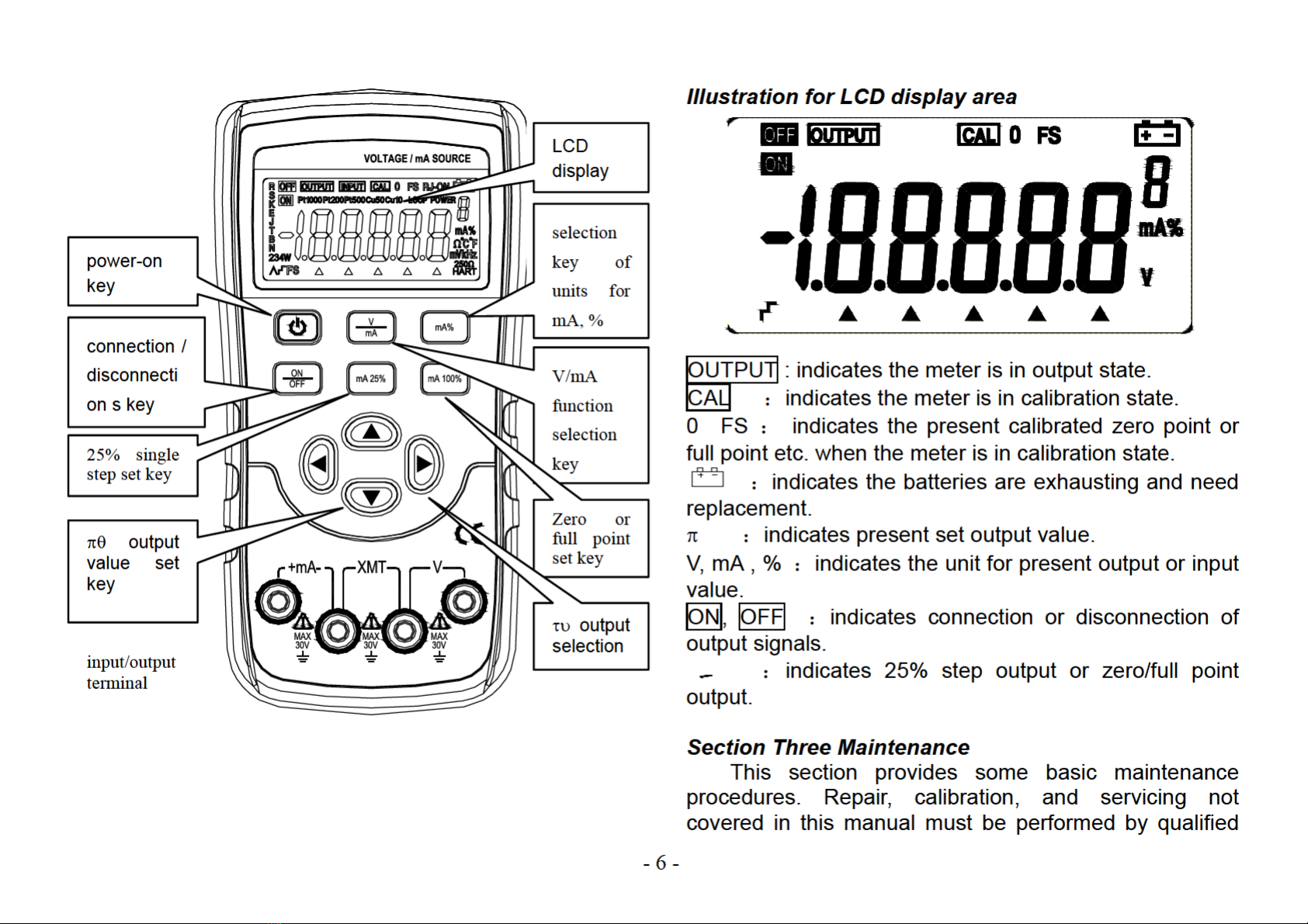
Section Two Components and functions of Meter’s
Panel


- 12 -
function ; The LCD displays symbol ‘AP-ON’, the meter
restores automatically power-off function.
Press 〔100%/START〕key to store selection.
The meter exits from maintenance state if cutting off
the power again.
Section Seven Performance Index
Accuracy is specified for a period of one year after calibration, at 23±5ºC, with relative humidity to 75%.
Accuracy specifications are given as: ± ([% of reading] + [number of least significant digits]) (“Counts” refers to
the number of increments or decrements of the least significant digit).
Output Range Output range Resolution Accuracy Illustration
DC voltage
DCV 10V 0.000~11.000V 0.001V 0.05%+2 Max. output current 5mA
DCA 20mA 0.000~22.000mA 0.001mA 0.05%+4uA 20mA Max. load 1KΩ
simulate
transmitter(sinking
current) -20mA 0.000~-22.000mA 0.001mA 0.05%+4uA
20mA Max. load 1KΩ
Note: power supply range: 5~
25VDC
Loop power 24V
±10% Max. output current 25mA
General Feature
zpower : two 1.5V alkaline batteries(LR6)
zpower consumption : about 400mA /3V, in condition of 1kΩload and 20mA output
zmaximum allowed
voltage :30V(within terminals or between terminal and earth ground)
zoperation temperature : 0°C~50°C

- 13 -
range
zoperation humidity
range :≤80%RH
zstorage temperature
range :≤- 10°C~55°C
zstorage humidity range : ≤90%RH
ztemperature coefficient : 0.1×(dedicated accuracy)%/℃(5℃~18℃、28℃~40℃)
zmeasurement : 180(L)×90(W)×47(D)mm(with protector)
zweight : about 500g
zaccessory : User’s Manual, industrial testing lead CF-36 (clips for probe)
zsafety : complies with IEC1010 (safety standard issued by International Electrician
Committee)
Section Eight Note for the Manual
zThe present operation instruction is subject to change without notice;
zThe content of the operation instruction is regarded as correct. Whenever any user finds its mistakes, omission, etc.,
he or she is requested to contact the manufacturer;
zThe present manufacturer is not liable for any accident and hazard arising from the customer misuse or inadvertent
operation;
zThe functions described in this operation instruction should not be used as grounds to apply this product to a
particular purpose.
Table of contents