Menvier 800 Series User manual

Cooper Lighting and Security
Wheatley Hall Road,
Doncaster,
South Yorkshire,
DN2 4NB
Tel: 01302 321 541
www.cooper-ls.com
INSTALLATION
MAB 800 Specification
Order Codes
Supply Voltage 18 - 30 V DC
Cable Size 0.5 - 2.5mm
Mounting Hole Centres 50 - 80mm
²
Recommended cable types FIRETUF,FP200 or MICC
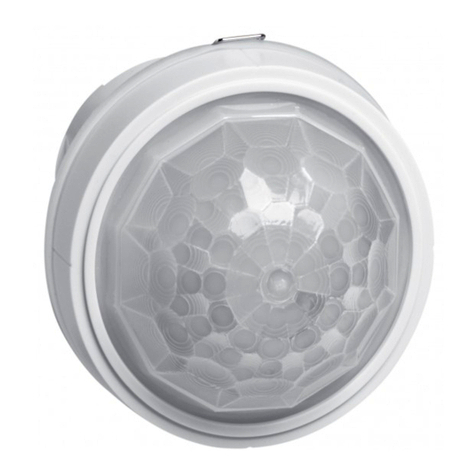
MAP820 Analogue Addressable Photoelectric Smoke Detector
MAI810 Analogue Addressable Ionisation Smoke Detector
MAH830 Analogue Addressable Heat Detector
MAOH850 Analogue Addressable Photo/ThermalDetector
Doc Ref: PINST800A ISS E
Wiring Hints
!Each terminal is suitable for clamping up to 2 wires
!Clamping of 2 wires of very different diameters under
one screw is not recommended.
!Suitable for mounting to mounting boxes with 50-
80mm fixing centres.
General
If difficulty is experienced when mounting the detector, this may
be due to the following:
!Wiring causing an obstruction - move or shorten wires.
!Although the base is tolerant to uneven mounting
surfaces, a very uneven surface may cause the base
to deform when the mounting screws are tightened
down - loosen screws to reduce this or slide base to a
more flat position.
WARNING: DO NOT USE HIGH VOLTAGE TESTERS
WHEN DETECTORS OR CONTROL PANEL
ARE CONNECTED TO THE SYSTEM.
Utilising Locking Tab
1
2
The mounting base includes an
optional feature to prevent the
removal of the detector without
the use of a tool.
1. Remove the standard fit
retaining clip.
2. Insert the locking clip which
is located at the centre of the
base as shown.
Mount the detector onto the base as described in Detector
Installation (see over) and rotate fully clockwise until it finally
clicks.
The detector is now locked into position. Remove by utilising a
suitable tool (eg a thin screwdriver) into the hole in the detector
cover. Gently push the tool into the detector and rotate anti-
clockwise.
+Remote
Indicator
LED
(optional)
+VIN
- VE COM OUT
2
4
1
3
2
4
1
3
Earth screen of cable to be continuous between detectors
S+
F
F+
S
_
_
__
_
_
_
_
_
_
DF6000
Analogue Addressable
Fire Alarm Panel
Loop Start
Loop Finish
- VE COM IN
Attention: If using the outer connection on terminal2, ensure the operation of the switch is not impeded and that there no shorts between
terminal 2 and the switch contact.
Ensure that the cable does not short onto the contact

Series 800 Range of Analogue Addressable Detectors - Technical Data Sheet
DETECTOR INSTALLATION
!Fit detector to mounting base and rotate clockwise until the detector drops into place.
!Continue to rotate clockwise until the detector clicks and no further rotation is possible.
!If the detectors are required to be locked into position, refer to the mounting base installation instructions (see over leaf).
!Smoke detectors are supplied fitted with dust covers for general protection against airborne contaminates. These must be removed from
all detectors before the fire system is commissioned.
!NB. These dust covers do not provide adequate protection against quantities of dust generated by building work, sanding etc. Therefore,
detectors should not be installed until this type of work has been completed.
Short Circuit Isolators
Each of the detectors in his range contain an integral
short circuit isolator, which operates between the -VE
COM IN terminal and the -VE COM OUT terminal
(terminals 1 & 2; see base wiring diagram overleaf).
The isolator operates in conjuction with the DF6000
Control Panel when a low parallel resistance fault of
typically 200Wis presented between the +VE and -
VE of the loop wiring.
TESTING
All detectors must be tested following installation or routine service and maintenance. It is recommended that these tests are carried out by a
competent person. Authorised personnel must be informed that the fire system will be temporarily out of service before commencing testing. To
prevent unwanted alarms, ensure that the control panel is in the ‘ One Man Walk Test’ mode. When all tests are complete, re-enable the previously
disabled zones and notify authorised personnel that the system is operational.
Smoke Detectors; Photo/Thermal Detector
!Subject the detector to be tested to a controlled amount of an approved synthetic smoke aerosol via a smoke detector test pole. Suitable
products are available for example, from No Climb Products Ltd.
!Check that the red LED on the detector lights within 30 seconds and the appropriate alarm address indication is displayed on the control
panel. If an optional remote LED is fitted, check that this also lights.
!Ensure that the control panel activates into alarm.
!The control panel will automatically reset after a few seconds.
!This procedure will test the smoke sensing circuitry of the Photo/Thermal Detector.
Heat Detectors; Photo/Thermal Detector
!Using a heat gun or hair dryer capable of generating temperatures of up to 95°C, direct the heat source towards the heat sensing
elements, visible through the side of the outer cover, from a distance of 15 to 30cm. Care should be taken not to allow the plastic surface
temperature to exceed 110°C otherwise damage may occur.
!When the temperature reaches the ‘Alarm Temperature’ (see Specifications above), check that the red LED on the detector lights and the
appropriate alarm address indication is displayed on the control panel. If an optional remote LED is fitted, check that this also lights.
!Ensure that the control panel activates into alarm.
!The control panel will automatically reset after a few seconds.
!This procedure will test the heat sensing circuitry of the Photo/Thermal Detector.
Maintenance
Only minimal maintenance can be performed on this range of detectors as they do not contain any site serviceable parts. The frequency of
maintenance will depend on the environment to which the detector is exposed but should be at least annually. Dusty or damp environments will
demand more frequent maintenance.
!Remove the detector from its mounting base.
!Use a vacuum cleaner to remove dust build up from around the smoke entry apertures of a smoke detector, or from around the heat
sensing element of a heat detector.
!For smoke detectors, visually inspect the insect mesh for blockages. If these can not be cleared by vacuuming, the detector must be
replaced.
!Re-fit detector to its mounting base and test as described above.
!Detectors that fail the testing procedure must be replaced.
Doc Ref: PINST800A ISS E
MAP820 MAI810 MAH830 MAOH850
Operating Voltage 18 to 30 Vdc 18 to 30 Vdc 18 to 30 Vdc 18 to 30
Vdc
Standby Current (max) 220mA220mA220mA220mA
Alarm Current (typ) 5mA 5mA 5mA 5mA
Ambient temperature (max) 60ºC 60ºC A1R 50ºC
BS 65°C
CS 80°C
50ºC
Ambient temperature (min) -20ºC -20ºC -20ºC -20ºC
Alarm temperature (static) N/A N/A A1R 60ºC
BS 77°C
CS 90°C
60ºC
Heat detector class –as
defined by EN54-5:2000
N/A N/A A1R, BS, CS
Control Panel
Selectable
A2S
Radioactive material / strength N/A Americium
18.5KBq
N/A N/A
Relative Humidity (non-
condensing)
0 to 95% 0 to 95% 0 to 95% 0 to 95%
Height (without base) 34mm 34mm 43mm 43mm
Height (with base) 47mm 47mm 56mm 56mm
Diameter 100.5mm 100.5mm 100.5mm 100.5mm
Weight (without base) 78g 86g 76g 78g
Material PC/ABS PC/ABS PC/ABS PC/ABS
Colour White White White White
Short Circuit Isolation Data
(Integral witheach detector)
Total Loop Resist ance for correct
operation of short c ircuit i solator 50Ù (max)
Continuous Current all owable through
isolator 700mA (max)
Isolator Resis tance in c losed st ate 0.13Ù (max)
Leakage Current into di rect short
circuit with isolat or open 13mA (max)
Parallel Fault Resist ance to be seen
at the Control P anel for isolators to
open
200Ù (typ)
This manual suits for next models
5
