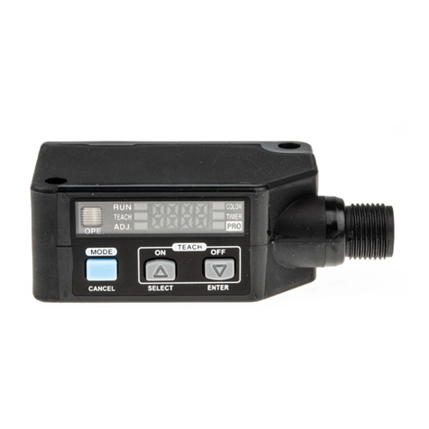
Sunx FX-301-F User manual

q
w
e
Fiber attachment
Fiber
Fiber
lock lever
Groove
Projection
Quick-connection cable
Projection
zSPECIFICATIONS
INSTRUCTION MANUAL
Digital Fiber Sensor
FX-301(P)-F
xCAUTIONS
䢇Make sure to carry out the wiring in the power supply off condition.
䢇Verify that the supply voltage variation is within the rating.
䢇Take care that if a voltage exceeding the rated range is applied, or if an AC power
supply is directly connected, the sensor may get burnt or damaged.
䢇In case noise generating equipment (switching regulator, inverter motor, etc.) is
used in the vicinity of this product, connect the frame ground (F.G.) terminal of the
equipment to an actual ground.
䢇If power is supplied from a commercial switching regulator, ensure that the frame
ground (F.G.) terminal of the power supply is connected to an actual ground.
䢇Do not use during the initial transient time (0.5 sec.) after the power supply is
switched on.
䢇Make sure to use an isolation transformer for the DC power supply. If an auto-
transformer (single winding transformer) is used, this product or the power supply
may get damaged.
䢇In case a surge is generated in the used power supply, connect a surge absorber
to the supply and absorb the surge.
䢇Take care that short-circuit or wrong wiring of the load may burn or damage the
sensor.
䢇Do not run the wires together with high-voltage lines or power lines or put them in
the same raceway.This can cause malfunction due to induction.
䢇Make sure to use the optional quick-connection cable for the connection of the
amplifier. Extension up to total 100m is possible with 0.3mm2, or more, cable.
However, in order to reduce noise, make the wiring as short as possible.
䢇
Take care that the sensor is not directly exposed to fluorescent light from a rapid-starter
lamp or a high frequency lighting device, as it may affect the sensing performance.
䢇This sensor is suitable for indoor use only.
䢇Avoid dust, dirt, and steam.
䢇When the fiber head gets dusty or dirty etc. the sensitivity deteriorates.To keep
stable detection, wipe the fiber head to remove dust or dirt etc. and carry out
sensitivity teaching periodically.
䢇Take care that the product does not come in direct contact with organic solvents,
such as, thinner, etc.
䢇
This sensor cannot be used in an environment containing inflammable or explosive gases.
䢇Never disassemble or modify the sensor.
For Leak/Liquid fiber
Thank you very much for using SUNX products.Please read this Instruction Manual
carefully and thoroughly for the correct and optimum use of this product. Kindly
keep this manual in a convenient place for quick reference.
This product is not a safety sensor. Its use is not intended or
designed to protect life and prevent body injury or property
damage from dangerous parts of machinery. It is a normal
object detection sensor.
3) The cable for amplifier connection is not supplied as an accessory. Make sure to use the
optional quick-connection cables given below.
Main cable (3-core): CN-73-C1 (cable length 1m), CN-73-C2 (cable length 2m)
CN-73-C5 (cable length 5m)
Sub cable (1-core): CN-71-C1 (cable length 1m), CN-71-C2 (cable length 2m)
CN-71-C5 (cable length 5m)
250μs
ON
OFF
Leak occurs Leak removed
1 sec.
approx.
cMOUNTING
How to remove the amplifier
How to connect the fiber cables
vCONNECTION
Connection method
Disconnection method
qPush the amplifier forward.
wLift up the front part of the amplifier to remove it.
Note: Take care that if the front part is lifted up without pushing
the amplifier forward, the hook on the rear portion of the
mounting section is likely to break.
qFit the rear part of the mounting section of the
amplifier on a 35mm width DIN rail.
wPress down the front part of the mounting section
of the amplifier on the 35mm width DIN rail.
How to mount the amplifier
qSnap the fiber lock lever down.
wInsert the fiber cables slowly into the inlets until
they stop. (Note 1)
eReturn the fiber lock lever to the original posi-
tion, till it stops.
Note: In case the fiber cables are not inserted to a position
where they stop, the sensing becomes unstable.
qHolding the connector of the quick-connection
cable, align its projection with the groove at the
top portion of the amplifier connector.
wInsert the connector till a click is felt.
qPressing the projection at the top of the quick-
connection cable connector, pull out the con-
nector.
Note:Take care that if the connector is pulled out without
pressing the projection, the projection may break.Do
not use a quick-connection cable whose projection
has broken. Further, do not pull by holding the cable,
as this can cause a cable-break.
Make sure to connect or disconnect the quick-connection cable in the power
supply off condition.
w
q
q
w
35mm width DIN rail
Notes: 1) 50mA if five, or more, amplifiers are con-
nected together.
2)If a leak is detected (Output: OFF) in
Leak (F7 mode), since the emission is
put in blinking operation, only the re-
sponse to return to ON gets delayed.
(1 sec.)
Make sure to fit the fiber attachment (FX-AT4), enclosed with the fiber, to the
fibers.
Please refer to the instruction manual of the fiber attachment for the fitting
method.
NPN output type PNP output type
FX-301-F FX-301P-F
FD-F7 series, FT-F9 series
12 to 24V DC ±10% Ripple P-P 10% or less
Normal operation: 960mW or less (Current consumption 40mA or less
at 24V supply voltage)
Eco-operation: 600mW or less (Current consumption 25mA or less at
24V supply voltage)
NPN open-collector transistor PNP open-collector transistor
•
Maximum sink current: 100mA (Note 1)
•
Maximum source current:100mA (Note 1)
• Applied voltage:30V DC or less • Applied voltage:30V DC or less
(between output and 0V) (between output and +V)
• Residual voltage:1.5V or less • Residual voltage:1.5V or less
[at 100mA (Note 1) sink current]
[at 100mA (Note 1) source current]
Type
Item Model No.
Applicable fiber
Supply voltage
Power consumption
Output operation
Short-circuit protection
Response time
Display
Sensitivity setting method
Fine sensitivity
adjustment function
Timer function
Ambient temperature
Ambient humidity
Emitting element
Material
Weight
Output
When Leak is set (F7 mode): OFF when leak is detected.
When Liquid is set (F9 mode):Selectable, either OFF when no liquid is
detected (NC) or ON when liquid is
detected (NO), with jog switch.
Incorporated
250
µ
s or less (Note 2)
4 digit red LED display
Individual teaching / Collective teaching
Incorporated
Incorporated with delay timer [Effective only when Liquid is set (F9 mode)]
0 to +50°C (If 8 to 16 units are connected together: 0 to +45°C)
(No dew condensation or icing allowed), Storage: –20 to +70°C
35 to 85% RH, Storage: 35 to 85% RH
Red LED (modulated)
Enclosure: Heat-resistant ABS, Transparent cover: Polycarbonate
20 g approx.
12/2002

bCASCADING AMPLIFIERS
䢇Make sure to add or remove the amplifiers in the power supply off condition.
䢇Make sure to check the allowable ambient temperature, as it depends on the
number of amplifiers connected in cascade.
䢇In case two, or more, amplifiers are connected in cascade, make sure to mount
them on a DIN rail.
䢇When connecting in cascade, mount the amplifiers close to each other, fitting
them between the optional end plates (MS-DIN-E) mounted at the two ends.
䢇
Up to maximum 15 amplifiers can be added (total 16 amplifiers connected in cascade.)
䢇When connecting more than two amplifiers in cascade, use the sub cable
(CN-71-
C
M
)
as the quick-connection cable for the second amplifier onwards.
䢇Since the model setting gets changed if collective teaching is done for the ampli-
fiers in Leak setting (F7 mode) and in Liquid setting (F9 mode) mounted in cas-
cade, note that collective teaching should not be done for amplifiers with different
model settings mounted in cascade.
䢇Since the communication function of this sensor and that of the digital fiber sen-
sor FX-301(P)/311(P) is different, if these models are mounted in cascade, do
not use the communication function.
䢇In case of cascading, wait for 10 minutes, or more, to use the teaching function
after the power is switched on.
qMount the amplifiers, one by one, on the
35mm width DIN rail.
(For details, refer to cMOUNTING.)
wSlide the amplifiers next to each other,
and connect the quick-connection cables.
eMount the optional end plates
(MS-DIN-E) at both the ends to hold the
amplifiers between their flat sides.
rTighten the screws to fix the end plates
(MS-DIN-E).
Cascading method
qLoosen the screws of the end plates
(MS-DIN-E).
wRemove the end plates (MS-DIN-E).
eSlide the amplifiers and remove them one
by one.
(For details, refer to cMOUNTING.)
Slide
Slide
35mm width
DIN rail
End plates
(MS-DIN-E)
(optional)
Sub cable
(CN-71-CM)
(optional)
Main cable
(CN-73-CM) (optional)
Dismantling method
nI/O CIRCUIT DIAGRAMS
䢇FX-301-F / NPN output type
D
Tr 100mA max. (Note 2)
11
2
3
3
2
Z
D
Terminal No.
+
V
Output
0V
Color code of quick-connection cable
(Brown)
+
V (Note 1)
(Black) Output
(Blue) 0V (Note 1)
Users’circuitInternal circuit
Load +
–
12 to 24V DC
±10%
Sensor circuit
Notes: 1) The quick-connection sub cable does not have +V (brown) and 0V (blue).The power is
supplied from the connector of the main cable.
2) 50mA max. if five, or more, amplifiers are connected together.
3) Do not use the amplifiers in a series (AND) connection.
Notes: 1) The quick-connection sub cable does not have +V (brown) and 0V (blue).The power is
supplied from the connector of the main cable.
2) 50mA max. if five, or more, amplifiers are connected together.
3) Do not use the amplifiers in a series (AND) connection.
mPART DESCRIPTION
1
2
3
1
3
2
100mA max. (Note 2)
Terminal No.
+V
Output
0V
Color code of quick-connection cable
(Brown) +V (Note 1)
(Black) Output
(Blue) 0V (Note 1)
Users’circuitInternal circuit
+
–
12 to 24V DC
±10%
D
Tr Z
D
Load
Sensor circuit
䢇FX-301P-F / PNP output type
,OPERATION PROCEDURE
䢇When the power supply is switched on, normal condition is displayed [MODE indi-
cator / RUN (green) lights up] and the digital display shows the incident light inten-
sity.
䢇When MODE key is pressed, the mode changes as per the diagram below. Fur-
ther, if the jog switch is pressed for 3 sec., or more, in ‘ADJ’, ‘DISP’or ‘OUT’con-
dition, SUB mode can be set.
Refer to
.RUN MODE.
Refer to ⁄4 FORCED
OUTPUT MODE.
RUN TEACH ALL
OUT
Refer to ⁄7 NO/NC
SELECTION FUNCTION.
Note 1: In Liquid setting (F9 mode) only.
.RUN MODE
䢇When MODE indicator / RUN (green) lights up, the display setting or the sensitiv-
ity select setting can be checked. Refer to ⁄5 SENSITIVITY SELECTION FUNC-
TION for further details of sensitivity select setting.
䢇When cJog switch is pressed for 2 sec., or more, the display changes as per the
diagram below.
How to change to ‘percent display’
䢇If xJog switch is turned to ‘+’or ‘–’side, the present sensitivity state can be
confirmed. After 2 sec., the display returns to ‘digit display’or ‘percent display’.
How to check the sensitivity state
⁄0 INDIVIDUALTEACHING MODE
Press
zMODE
DISP
Refer to
⁄0
INDIVIDUAL
TEACHING MODE.
Refer to
⁄1
COLLECTIVE
TEACHING MODE.
Refer to
⁄6 TIMER FUNCTION.
Refer to
⁄3
DIGITAL DISPLAY
SETTING MODE.
ADJ
Refer to ⁄5 SENSITIVITY
SELECTION FUNCTION.
Refer to
⁄2
THRESHOLD LEVEL
FINE ADJUSTMENT MODE.
MAIN
mode
SUB
mode
Press cJog switch
for 3 sec., or more.
(Note 1)
Press cJog switch
for 2 sec., or more.
Or
䢇
When MODE indicator /TEACH (yellow) lights up, threshold value can be set on a single unit.
Notes: 1)For details, refer to ⁄8 ERROR INDICATION.
2)The initial setting at the time of factory shipment is Liquid (F9) mode (
-F9-
).
Step Description
MODE key Press Used for mode selection or cancellation during setting.
(Note 2)
Turn Used to select each item.
Press Used to enter each item.
Jog switch
MODE indicator / ADJ (Yellow)
MODE indicator / DISP (Yellow)
MODE key
Jog switch
MODE indicator /
OUT (Yellow)
Digital display (Red)
MODE indicator / ALL (Yellow)
MODE indicator / TEACH (Yellow)
MODE indicator / RUN (Green)
Output operation
indicator (Orange) Model indicator
(Green)
Note 2:When zMODE key is pressed for 1 sec., or more, the sensor returns to the RUN mode.(in
MAIN mode only)
Symbols... D : Reverse supply polarity protection diode
ZD: Surge absorption zener diode
Tr : NPN output transistor
Symbols... D : Reverse supply polarity protection diode
ZD: Surge absorption zener diode
Tr : PNP output transistor
Terminal
arrangement
diagram
Terminal
arrangement
diagram
Press
zMODE
Press
zMODE Press
zMODE
Press
zMODE Press
zMODE
Press cJog switch
for 3 sec., or more.
(Note 1)
Press
c
Jog switch
for 3 sec., or more.
The incident light intensity is dis-
played within the range 0 to 4,000. The incident light intensity is displayed in
percentage (within 0 to 999) based on the
threshold value as the reference.
Lo
Operating in the low sensitivity mode.
<LO mode>
HI
Operating in the high sensitivity mode.
<HI mode>
The sensitivity selection function is set to the automatic sensitivity setting (
Auto
)
at the time of factory shipment. In case sensitivity selection setting is done,
make sure to carry out ‘teaching’after the sensitivity selection setting.
For the sensitivity selection setting, refer to ⁄5
SENSITIVITY SELECTION FUNCTION
.
<Percent display>
123P
<Digit display>
1234
q
w
e
t
Step Display Description
•Insert Leak detection fiber (FD-F7M) or Liquid detection fiber
(FT-F9M).
•Press zMODE key to light up MODE indicator /TEACH (yellow).
r
•Turn xthe jog switch to ‘+’or ‘–’side to set to either Leak (F7)
mode (
-F7-
) or Liquid (F9) mode (
-F9-
).
•In case Liquid (F9) mode (
-F9-
) is set, the model indicator (Green)
lights up.
•Press cJog switch in no-leak condition with Leak detection fiber
(FD-F7M) or no-liquid condition with Liquid detection fiber (FT-F9M).
Then, ‘
1
’on the display moves from left to right.
•When teaching is accepted, the result of threshold value setting is
displayed.
In case stable sensing is possible:‘
9ood
’on the display blinks
three times.
In case stable sensing is not possible:‘
Er-3
' on the display blinks.
(Note 1)
•
If the teaching result is‘
9ood
’, the sensor returns to RUN mode au-
tomatically and the incident light intensity is shown on the display.
•MODE indicator / RUN (green) lights up.
•The setting is complete.
1234
-F7-
-F9-
1
9ood
Er-3
1234
12/2002

OUT
DISP
ADJ
ALL
TEACH
RUN
OUT
DISP
ADJ
ALL
TEACH
RUN
OUT
DISP
ADJ
ALL
TEACH
RUN
OUT
DISP
ADJ
ALL
TEACH
RUN
OUT
DISP
ADJ
ALL
TEACH
RUN
OUT
DISP
ADJ
ALL
TEACH
RUN
OUT
DISP
ADJ
ALL
TEACH
RUN
OUT
DISP
ADJ
ALL
TEACH
RUN
OUT
DISP
ADJ
ALL
TEACH
RUN
OUT
DISP
ADJ
ALL
TEACH
RUN
OUT
DISP
ADJ
ALL
TEACH
RUN
OUT
DISP
ADJ
ALL
TEACH
RUN
OUT
DISP
ADJ
ALL
TEACH
RUN
OUT
DISP
ADJ
ALL
TEACH
RUN
OUT
DISP
ADJ
ALL
TEACH
RUN
OUT
DISP
ADJ
ALL
TEACH
RUN
Direction of transmission
⁄1 COLLECTIVETEACHING MODE
䢇When MODE indicator / ALL (yellow) lights up, a threshold value can be collec-
tively set to amplifiers mounted in cascade.
Notes: 1)For details, refer to ⁄8 ERROR INDICATION.
2) In collective teaching, only an instruction of the teaching operation is transmitted, the thresh-
old value is not copied.The threshold value taught at the respective amplifier is set.
3) When the collective teaching is done, the setting conditions are copied. In case an indi-
vidual setting condition is desired to be set, set it individually after the collective teaching.
4) The collective teaching transmits the information only in the direction of the arrow shown
on the amplifier operation panel.The collective teaching is also possible from the middle of
the amplifiers mounted in cascade. Check the direction of the transmission before collec-
tive teaching is done.
5) Since the model setting is also transmitted, do not carry out collective teaching when the
amplifiers in Leak (F7) mode (
-F7-
) and in Liquid mode (F9) mode (
-F9-
) are mixed in
cascade connection.
⁄2
THRESHOLDVALUE FINE ADJUSTMENT MODE
䢇When MODE indicator / ADJ (yellow) lights up, the set threshold value can be fine
adjusted.
Note: The adjustable area is limited as shown below. In order to adjust the threshold the outside the
adjustable area, confirm it within the area once and then adjust it again.
⁄3 DIGITAL DISPLAY SETTING MODE
䢇When MODE indicator / DISP (yellow) lights up, the digital display can be switched
to the light-up mode, the eco mode or the inverse mode.
Note: The initial setting at the time of factory shipment is the light-up mode (
EcoF
).
⁄4 FORCED OUTPUT MODE
䢇When MODE indicator / OUT (yellow) lights up, the output can be compulsory
changed to ON or OFF regardless of the incident light intensity.
⁄5 SENSITIVITY SELECTION FUNCION
䢇If Jog switch is pressed for 3 sec., or more, when MODE indicator / ADJ (yellow)
lights up, the sensitivity can be fixed to low sensitivity or high sensitivity, or set to
automatic sensitivity.
Note: The initial setting at the time of factory shipment is the automatic sensitivity setting (
Auto
).
Adjustable area in Leak (F7) mode: 70 to 110% Adjustable area in Liquid (F9) mode: 90 to 130%
110
70
Light amount
(%)
Threshold value
(100)
90
130
Adjustable
area
Adjustable
area
Leak detection side
Liquid present detection side
(100)
Threshold
value
Light amount
(%)
Mode
Digitdisplay
Model setting
Digital
Sensitivity
Timer function
NO/NCselec-
Percent display
display setting
selection function
tion function
Leak (F7) mode ××
Liquid (F9) mode
: Copied, ×: Not copied
q
w
e
Step Display Description
•Press zMODE key to light up MODE indicator / DISP (yellow).
r
•When xJog switch is turned to the ‘+’side or ‘–’side, the mode in
the digital display changes.
EcoF
:This is the light-up mode in the digital display.
The digital display always lights up.
Econ
:
This is the eco mode. After confirmation, if key operation has not
been done for 8 sec., or more, ‘
Eco
’flashes, and then the digital
display is turned off.
When a key operation is done after the display is turned off or when
the collective teaching is carried out, the digital display lights up.
turn
:
This is the inverse mode of the digital display.
In the normal display condition, the display changes to the inverse display
and in the inverse condition, the display changes to the normal display.
•When zMODE key is pressed twice or for 1 sec., or more, the sen-
sor returns to RUN mode and the incident light intensity is displayed.
•MODE indicator / RUN (green) lights up.
•The setting is complete.
EcoF
EcoF
Econ
turn
Econ
1234
•When cJog switch is pressed, the set display blinks 3 times and is
confirmed.
q
w
e
t
Step Display Description
•Press zMODE key to light up MODE indicator / ADJ (yellow).
r
•Press cJog switch for 3 sec. or more.
(The sensor goes into the sensitivity setting condition.)
•MODE indicator / RUN (green) blinks.
•When xJog switch is turned to the ‘+’side or ‘–’side, the display
and MODE indicator / RUN (green) blinks, and the sensitivity can be
selected.
Auto
:Automatic sensitivity setting
After selecting the automatic sensitivity, the optimum sensi-
tivity is set by carrying out teaching.
Lo
:Low sensitivity setting
HI
:High sensitivity setting
•When cJog switch is pressed, the setting display blinks 3 times
and is confirmed.
•MODE indicator / TEACH (green) lights up and ‘
-F7-
’or ‘
-F9-
’is
displayed.
•After sensitivity selection, carry out the teaching.
For the setting method of teaching, refer to ⁄0 INDIVIDUALTEACH-
ING MODE.
1234
Auto
Auto
Lo
HI
Lo
-F7-
-F9-
q
w
e
t
Step Display Description
•Insert Leak detection fiber (FD-F7M) or Liquid detection fiber
(FT-F9M).
•Press zMODE key to light up MODE indicator / ALL (yellow).
r
•Turn xthe jog switch to ‘+’or ‘–’side to set to either Leak (F7)
mode (
-F7-
) or Liquid (F9) mode (
-F9-
).
•In case Liquid (F9) mode (
-F9-
) is set, the model indicator (Green)
lights up.
•Press cJog switch in no-leak condition with Leak detection fiber
(FD-F7M) fitted or no-liquid condition with Liquid detection fiber fitted
(FT-F9M). Then, ‘
@
’on the display moves from top left to top
right and from bottom right to bottom left (twice).
•When teaching is accepted, the result of threshold value setting is
displayed.
In case stable sensing is possible: ‘
9ood
’on the display blinks
three times.
In case stable sensing is not possible:‘
Er-3
' on the display blinks.
(Note 1)
•
If the teaching result is‘
9ood
’, the sensor returns to RUN mode au-
tomatically and the incident light intensity is shown on the display.
•MODE indicator / RUN (green) lights up.
•The setting is complete.
1234
-F7-
-F9-
@
9ood
Er-3
1234
q
w
e
Step Display Description
•Press zMODE key to light up MODE indicator / DISP (yellow).
(Present output state is displayed.)
r
•When xJog switch is turned to the ‘+’side or ‘–’side, the output is
compulsory changed to ON or OFF.
•Since the emitting element of the amplifier blinks, it is possible to
check the fiber connected to the amplifier.
•When the output is compulsory changed to ON, the operation indi-
cator (orange) lights up.
•When zMODE key is pressed, the sensor returns to RUN mode
and the incident light intensity is displayed.
•MODE indicator / RUN (green) lights up.
•The setting is complete.
on
oFF
on
1234
•Press zMODE key to return the sensor to step q.
q
w
e
Step Display Description
•Press zMODE key to light up MODE indicator / ADJ (yellow).
r
•Turn xJog switch to the ‘+’side, to increase the threshold value.
•Turn xJog switch to the ‘–’side, to decrease the threshold value.
1234
1235
1235
1234
•
When
z
MODE key is pressed 3 times, or for 2 sec., or more, the sensor re-
turns to the RUN mode and the incident light intensity is shown in the display.
•MODE indicator / RUN (green) lights up.
•The setting is complete.
•When cJog switch is pressed, the changed threshold value blinks
3 times and is confirmed.
12/2002

⁄6 TIMER FUNCTION [Liquid (F9) mode only]
䢇The timer setting can be done by pressing the jog switch for 3 sec., or more, when
Liquid (F9) mode (
-F9-
) has been set and MODE indicator / DISP (yellow) lights
up. In case of Leak (F7) mode (
-F7-
), the display does not change to the timer
function.
For the selection method of Leak (F7) mode / Liquid (F9) mode, refer to ⁄0 INDI-
VIDUALTEACHING MODE or ⁄1 COLLECTIVETEACHING MODE.
䢇This product incorporates a delay timer which reduces the effect of air bubbles,
etc.
⁄7
NO/NC SELECTION FUNCTION [Liquid (F9) mode only]
䢇The NO/NC selection can be done by pressing the jog switch for 3 sec., or more,
when Liquid (F9) mode (
-F9-
) has been set and MODE indicator / DISP (yellow)
lights up.In case of Leak (F7) mode (
-F7-
), the display does not change to NO/
NC selection function.
For the selection method of Leak (F7) mode / Liquid (F9) mode, refer to ⁄0 INDI-
VIDUAL TEACHING MODE or ⁄1 COLLECTIVETEACHING MODE.
⁄8 ERROR INDICATION
䢇When an error is displayed, remedy as follows.
⁄9 DIMENSIONS
27.8 7
10.5
3.95
36.513.5
364.53
30.5
3
Communication
window
Suitable for 35mm width DIN rail
7
7
10
Emission
part
Receiving
part
0.7
48.2 12
26.32.58.3
MODE key
Jog switch
Digital display (Red)
Model indicator (Green)
Output operation indicator (Orange)
Timer
operation
Sensing
condition
NO/NC
selection
function
Liquid
present
Liquid
absent
NormalDelay timer
TT T
NC
Normal
close
()
NC
Normal
close
()
NO
Normal
open
()
NO
Normal
open
()
ON
OFF
ON
OFF
ON
OFF
TT T ON
OFF
Timer period:T=10ms, 100ms, 1,000ms
<Time chart>
http://www.sunx.co.jp/
PRINTED IN JAPAN
Head Office
2431-1 Ushiyama-cho, Kasugai-shi, Aichi, 486-0901, Japan
Phone: +81-(0)568-33-7211 FAX: +81-(0)568-33-2631
Overseas Sales Dept.
Phone: +81-(0)568-33-7861 FAX: +81-(0)568-33-8591
SUNXLimited
Note: The initial setting at the time of factory shipment is the without timer (
non
) condition.
q
w
e
t
Step Display Description
•Press zMODE key to light up MODE indicator / DISP (yellow).
r
•Press cJog switch for 3 sec., or more.
(The sensor goes into the timer setting condition.)
•MODE indicator / RUN (green) blinks.
•When xJog switch is turned to the ‘+’side or ‘–’side, the display
and MODE indicator / RUN (green) blinks, and the timer period can
be chosen.
non
:Without timer
10
:10ms timer
100
:100ms timer
1000
:1,000ms timer
•When cJog switch is pressed, setting display blinks 3 times and is
confirmed.
•When zMODE key is pressed twice or for 1 sec., or more, the sen-
sor returns to RUN mode and the incident light intensity is displayed.
•MODE indicator / RUN (green) lights up.
•The setting is complete.
-F9-
EcoF
non
non
100
1000
1234
10
EcoF
10
u
y
•Confirm if the sensor is in Liquid (F9) mode (
-F9-
) in ⁄0 INDIVIDUAL
TEACHING MODE or ⁄1 COLLECTIVE TEACHING MODE.
•The sensor returns to step w.
Note: The initial setting at the time of factory shipment is the normal close (
nc
) setting.
q
w
e
t
Step Display Description
•Press zMODE key to light up MODE indicator / OUT (yellow).
r
•Press cJog switch for 3 sec., or more.
(The sensor goes into the NO/NC setting condition.)
•MODE indicator / RUN (green) blinks.
•When xJog switch is turned to the ‘+’side or ‘–’side, the display
and MODE indicator / RUN (green) blinks, and NO/NC can be cho-
sen.
nc
:Normal close (OFF in liquid absent condition.)
no
:Normal open (OFF in liquid present condition.)
•When cJog switch is pressed, setting display blinks 3 times and is
confirmed.
•When zMODE key is pressed, the sensor returns to RUN mode
and the incident light intensity is displayed.
•MODE indicator / RUN (green) lights up.
•The setting is complete.
-F9-
on
nc
nc
no
on
1234
no
u
y
•Confirm if the sensor is in Liquid (F9) mode (
-F9-
) in ⁄0 INDIVIDUAL
TEACHING MODE or ⁄1 COLLECTIVETEACHING MODE.
•The sensor returns to the step w.
Error indication Cause Remedy
Er-1
Er-3
Er-5
•Excessive current
flows due to a short-
circuit.
•The teaching is
abnormal.
•The communica-
tion is abnormal.
•Switch off the power supply and check the load.
•
Check the installation condition of the fiber, or whether
the fiber has come out, and then do teaching again.
•
Press zMODE key to cancel‘
Er-3
’. After the cancella-
tion, the sensor operates at the set value conditions be-
fore the error. However, in case the sensitivity selection
function has been set to the automatic sensitivity setting
(
Auto
), the sensor operates at optimum sensitivity.
•Check if the amplifiers mounted in cascade are
disconnected.After the confirmation, do the teach-
ing again.
12/2002
This manual suits for next models
1
Other Sunx Security Sensor manuals
Popular Security Sensor manuals by other brands

Niko
Niko 350-41650 Technical manual

Visonic
Visonic MR-4000 installation instructions

teko
teko Astra-361 operating manual

PCB Piezotronics
PCB Piezotronics Tourmaline ICP 138A26 Installation and operating manual

Smoke Guard
Smoke Guard M2500 Smoke Operation & maintenance manual

Trotec
Trotec BE16 operating manual