MERAWEX ZSP100 Series User manual

Instrukcja obsługi ZSP100 0658.00.95-06.0 1/30
MERAWEX Sp. z o.o.
44-122 Gliwice
ul. Toruńska 8
tel. +48 32 23 99 400
fax +48 32 23 99 409
[email protected]om.pl
http://www.merawex.com.pl INSTRUKCJA OBSŁUGI
Zasilacze do urządzeń sygnalizacji pożarowej, systemów kontroli rozprzestrzeniania
dymu i ciepła oraz urządzeń przeciwpożarowych i automatyki pożarowej,
zgodne z normą EN 54-4:1997 + AC:1999 + A1:2002 + A2:2006
i EN 12101-10:2005 + AC:2007
ZSP100-1.5A-07, ZSP100-1.5A-18, ZSP100-2.5A-07, ZSP100-2.5A-18
ZSP100-4.0A-07, ZSP100-4.0A-18, ZSP100-4.0A-40
ZSP100-5.5A-07, ZSP100-5.5A-18, ZSP100-5.5A-40
ZSP100-7.5A-18, ZSP100-7.5A-40, ZSP100-7.5A-75
ZSP100-10A-18, ZSP100-10A-40, ZSP100-10A-75
ZSP100-12A-18, ZSP100-12A-40, ZSP100-12A-75
03.03.2020
Certyfikat stałości właściwości użytkowych CNBOP-PIB Nr 1438-CPR-0454
Deklaracja właściwości użytkowych Nr DWU-MX-08
Świadectwo dopuszczenia CNBOP-PIB Nr 2582/2016
Ostrzeżenia
Należy przeczytać wszystkie poniższe wskazówki i przepisy. Błędy w ich przestrzeganiu mogą
spowodować uszkodzenie urządzenia, porażenie prądem, pożar lub ciężkie obrażenia ciała.
▪Zabrania się przenoszenia i transportu urządzenia z zamontowanymi i dołączonymi
akumulatorami. Może to spowodować powstanie poważnych wewnętrznych uszkodzeń
do utraty bezpieczeństwa użytkowania włącznie.
▪Montaż i podłączenia mogą być wykonane jedynie z wyjętymi akumulatorami.
▪Przy podłączaniu stanowiących zagrożenie wysokim poziomem energii baterii
akumulatorów należy zwrócić szczególną uwagę na zgodność ich biegunowości
z opisem na złączu.
▪Nie przesłaniać otworów wentylacyjnych. Należy zapewnić wolną przestrzeń co najmniej
10 cm z boków urządzenia umożliwiając jego poprawną wentylację. W przeciwnym
wypadku może dojść do uszkodzenia urządzenia lub przedwczesnego zużycia baterii
akumulatorów.
▪Urządzenie zamontować w miejscu gdzie nie będzie narażone na bezpośrednie
oddziaływanie promieni słonecznych.
▪Urządzenie musi być zasilane z sieci elektroenergetycznej z zaciskiem uziemienia
ochronnego.
▪Przed załączeniem urządzenia do pracy należy sprawdzić jakość wszystkich wykonanych
połączeń.
▪Urządzenie może zakłócić pracę czułych urządzeń radiowo telewizyjnych umieszczonych
w pobliżu.
▪Obsługą urządzenia może zajmować się wyłącznie uprawniony i wyszkolony personel.
▪Urządzenie może być serwisowane wyłącznie przez służbę serwisową producenta lub
wyspecjalizowane jednostki upoważnione przez producenta.
Instrukcja obsługi ZSP100 0658.00.95-06.0 2/30
Opis techniczny
Zasilacze przeznaczone są do bezprzerwowego zasilania urządzeń przeciwpożarowych o napięciu
24 V, spełniając wymagania norm EN 54-4 + AC + A1 + A2 i EN 12101-10 + AC. Źródłem zasilania
rezerwowego są dwa, 12 V akumulatory kwasowo-ołowiowe typu VRLA. Zasilacze przeznaczone są do
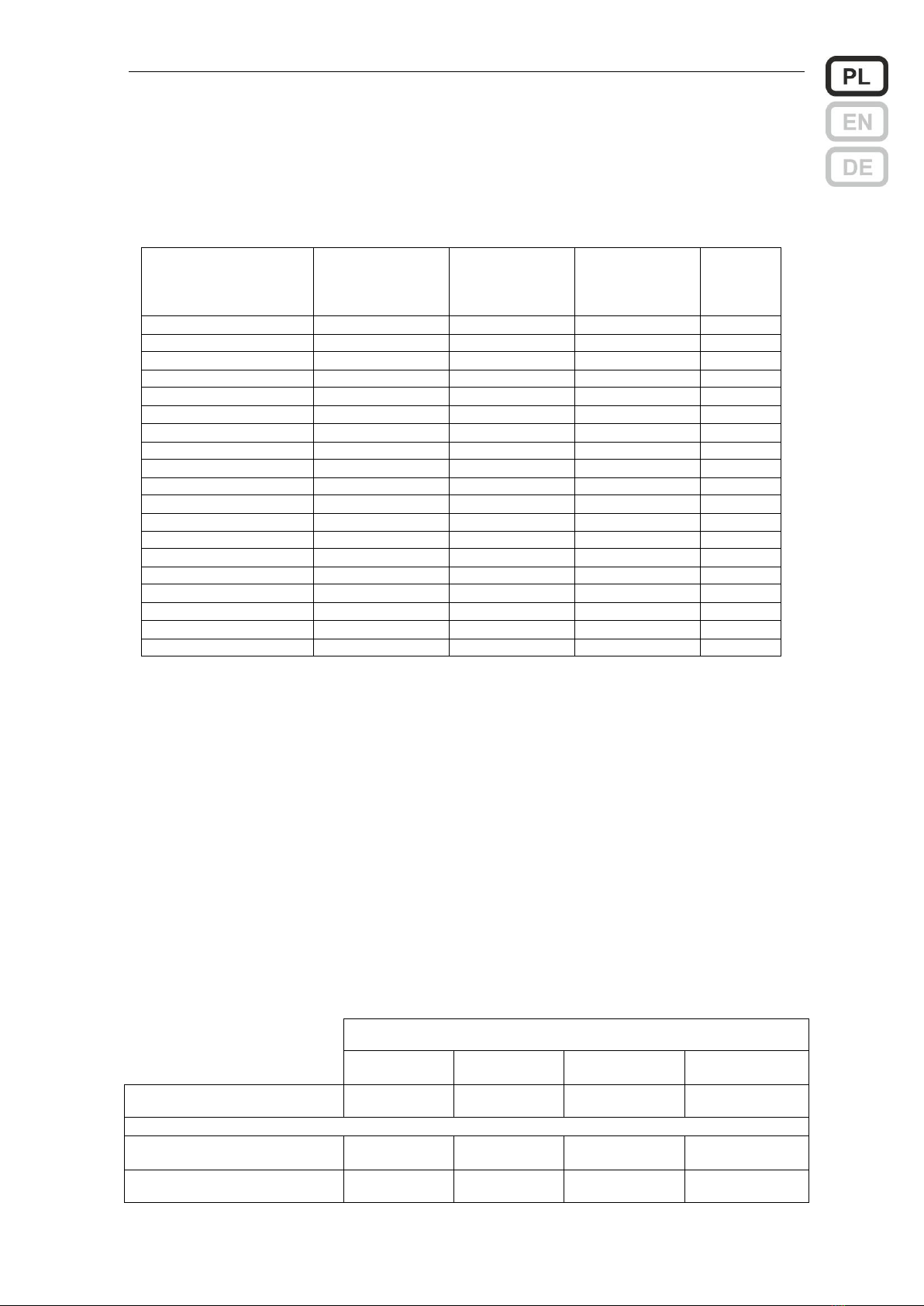
montażu naściennego. Wszystkie 19 wykonań w czterech typach szafek opisuje poniższa tabela.
Wersje zasilaczy ZSP100
Zasilacz w szafce
Blok zasilacza
Maksymalny
prąd wyjściowy
Bateria
akumulatorów
Typ szafki
ZSP100-1.5A-07
ZSPM-75-05
1.5 A
7…9 Ah
7
ZSP100-1.5A-18
ZSPM-75-10
1.5 A
7…20 Ah
18
ZSP100-2.5A-07
ZSPM-75-05
2.5 A
7…9 Ah
7
ZSP100-2.5A-18
ZSPM-75-10
2.5 A
7…20 Ah
18
ZSP100-4.0A-07
ZSPM-150-05
4.0 A
7…9 Ah
7
ZSP100-4.0A-18
ZSPM-150-10
4.0 A
7…20 Ah
18
ZSP100-4.0A-40
ZSPM-150-20
4.0 A
17…45 Ah
40
ZSP100-5.5A-07
ZSPM-150-05
5.5 A
7…9 Ah
7
ZSP100-5.5A-18
ZSPM-150-10
5.5 A
7…20 Ah
18
ZSP100-5.5A-40
ZSPM-150-20
5.5 A
17…45 Ah
40
ZSP100-7.5A-18
ZSPM-200-18
7.5 A
7…20 Ah
18
ZSP100-7.5A-40
ZSPM-200-33
7.5 A
17…45 Ah
40
ZSP100-7.5A-75
ZSPM-200-33
7.5 A
17…75 Ah
75
ZSP100-10A-18
ZSPM-320-18
10 A
7…20 Ah
18
ZSP100-10A-40
ZSPM-320-33
10 A
17…45 Ah
40
ZSP100-10A-75
ZSPM-320-33
10 A
17…75 Ah
75
ZSP100-12A-18
ZSPM-320-18
12 A
7…20 Ah
18
ZSP100-12A-40
ZSPM-320-33
12 A
17…45 Ah
40
ZSP100-12A-75
ZSPM-320-33
12 A
17…75 Ah
75
Kompletacja zasilaczy
•szafka zasilacza z zamontowanym
wewnątrz blokiem zasilacza
•dławnice: DW16-RM 1 szt. DW20-
RM 3 szt.
Wyposażenie opcjonalne
•4 uchwyty do montażu szafki
z odsadzeniem od ściany
•moduł 6 wyjść dodatkowych typu
ZSP100-OUT6 lub ZSP101-OUT6 *)
•czujnik otwartych drzwi szafki wraz
z przewodami
•dodatkowe dławnice
*) ZSP100-OUT6 występuje z konkretnymi wartościami bezpieczników, np. ZSP100-OUT6-1.0AF wskazuje na
zastosowanie bezpieczników szybkich (F) o nominale 1 A (1.0 A).
ZSP101-OUT6 pozwala na zastosowanie dowolnych bezpieczników z zakresu od 0.2 A do 10 A, zgodnie
z potrzebami użytkownika.
Szafki posiadają przygotowane, lecz jeszcze zaślepione otwory pod dławnice w jej części górnej i na
lewym boku oraz dodatkowo prostokątne wycięcie od strony ściany, do przeprowadzenia przewodów
elektrycznych. Przed montażem szafki, należy wybrać sposób doprowadzenia przewodów, usunąć
odpowiednie zaślepki przez ich wyłamanie i zamontować dławnice w wymaganej ilości i miejscu.
Wymiary gabarytowe i
montażowe zasilaczy
Typ szafki
7
18
40
75
Wymiary gabarytowe
(S x W x G) [mm]
340 x 250 x 80
395 x 356 x 96
455 x 356 x 187
555 x 406 x 187
Mocowanie
- wewnątrz szafki
(S x W) [mm]
276 x 182
350 x 282
410 x 282
510 x 332
- przy zastosowaniu
uchwytów (S x W) [mm]
276 x 270
350 x 370
410 x 370
510 x 420

Instrukcja obsługi ZSP100 0658.00.95-06.0 3/30
Masa bez baterii akumulatorów
- max
3.1 kg
4.9 kg
7.6 kg
11.4 kg
Masa z bateriami akumulatorów
- max
8.4 kg
17.2 kg
36.6 kg
57.4 kg
Otwory pod dławnice
- w części górnej
6x DW20-RM, 1x DW16-RM
- w lewym boku
3x DW20-RM,
1x DW16-RM
6x DW20-RM,
1x DW16-RM
6x DW20-RM,
1x DW16-RM
6x DW20-RM,
1x DW16-RM
Widok zasilacza i rozstaw
otworów do jego zamocowania
(poniżej) na przykładzie szafki
18
Na drzwiach szafki zamiennie
mogą być stosowane oznaczenia:
230V AC lub
ALARM lub
17.3
350
282
350
370
8
6.5
12
6.5
Szafkę należy przymocować do ściany za pomocą 4 stalowych śrub. Nie można stosować
plastikowych kołków rozporowych. Przed montażem celowe jest wyjęcie bloku zasilacza przez
odkręcenie dwóch nakrętek w jego dolnej części, lekkie odchylenie i wysunięcie całego bloku w dół.
Po zawieszeniu szafki należy z powrotem zamontować blok zasilacza.
Podstawowe parametry elektryczne i środowiskowe
Znamionowe napięcie zasilania *1)
110 / 230V +10% -15%
Znamionowe napięcie wyjściowe *2)
27.1 V
Zakres zmian napięcia wyjściowego *3)
21.0 … 28.8 V
Pobór prądu z akumulatora na potrzeby własne zasilacza
•maks. 17 mA (wersje 1.5 –5.5 A)
•maks. 25 mA (wersje 7.5 –12 A)
Sprawność przy nominalnym obciążeniu i naładowanej bat.
89%
Maksymalna rezystancja obwodu akumulatora
(wersje 1.5 –5.5 A) *4)
250 mΩ
96 395
356
ZSP100

Instrukcja obsługi ZSP100 0658.00.95-06.0 4/30
Maksymalna rezystancja obwodu akumulatora
(wersje 7.5 –12 A) *4)
100 mΩ (150 mΩ dla szafki 18)
Liczba współpracujących akumulatorów
2
Liczba wyjść zabezpieczonych osobnymi bezpiecznikami
•2 (wersje 1.5 –5.5 A)
•5 (wersje 7.5 –12 A)
Temperatura pracy
-5…+55°C
Stopień ochrony EN 60529:1991 + A1:2000
IP 42
Klasa funkcjonalna / środowiskowa EN 12101-10:2005 +
AC:2007
A / 2
Klasa ochronności EN 60950-1:2006 + A11:2009 + A1:2010
+ A12:2011 + A2:2013
I
*1) Aby zasilać z sieci 110 V, w zasilaczach ZSP100 zawierających zasilacz ZSPM-150 należy przełącznik
napięcia sieci przełączyć w położenie 115 V; nie dotyczy to wersji zasilaczy ZSP100 zawierających ZSPM-75,
ZSPM-200, ZSPM-320
*2) W cyklu pracy buforowej w temperaturze 25
C
*3) Podany zakres obejmuje napięcia pomiędzy napięciem rozładowanej baterii akumulatorów (pod koniec
cyklu pracy bateryjnej) do napięcia ładowania przyspieszonego.
*4) Wartość rezystancji obwodu akumulatora, przy której zostanie uruchomiona sygnalizacja uszkodzenia.
Parametry prądowe zasilaczy
Typ
Bateria
Prąd
ładowania
Imax_b
Imax_a
EN 54-4
Imax_a EN 12101-10
72 h
30 h
4 h
Ah
A
A
A
A
A
A
ZSP100-1.5A-07
9
0.5
1.5
1.1
0.08
0.21
1.10
ZSP100-1.5A-18
20
1.0
1.5
0.6
0.20
0.49
0.62
ZSP100-2.5A-07
9
0.5
2.5
2.1
0.08
0.21
1.30
ZSP100-2.5A-18
20
1.0
2.5
1.6
0.19
0.49
1.62
ZSP100-4.0A-07
9
1.0
4.0
3.6
0.07
0.20
1.26
ZSP100-4.0A-18
20
1.0
4.0
3.1
0.19
0.49
2.95
ZSP100-4.0A-40
45
2.0
4.0
2.0
0.46
1.13
2.02
ZSP100-5.5A-07
9
0.5
5.5
5.1
0.07
0.20
1.21
ZSP100-5.5A-18
20
1.0
5.5
4.6
0.19
0.48
2.92
ZSP100-5.5A-40
45
2.0
5.5
3.5
0.46
1.13
3.52
ZSP100-7.5A-18
20
1.8
7.5
6.6
0.20
0.51
3.11
ZSP100-7.5A-40
45
3.3
7.5
5.6
0.49
1.21
5.56
ZSP100-7.5A-75
75
3.3
7.5
4.3
0.84
2.04
4.26
ZSP100-10A-18
20
1.8
10
9.1
0.19
0.50
3.03
ZSP100-10A-40
45
3.3
10
8.1
0.49
1.20
7.21
ZSP100-10A-75
75
3.3
10
6.8
0.83
2.04
6.76
ZSP100-12A-18
20
1.8
12
11.1
0.19
0.49
2.96
ZSP100-12A-40
45
3.3
12
10.1
0.48
1.20
7.16
ZSP100-12A-75
75
3.3
12
8.8
0.83
2.03
8.76
Uwagi:
- oznaczenia Imax_a i Imax_b są zgodne z EN 54-4.
- prąd Imax_b może być pobrany w całości z wyjścia OUT-1 lub jako suma prądów obu wyjść OUT-1 i OUT-2
(dotyczy wersji 1.5 ÷5.5 A)
- prąd Imax_b może być pobrany w całości z wyjścia OUT-5 lub jako suma prądów ze wszystkich 5 wyjść
zasilacza (dotyczy wersji 7.5 ÷12 A)
- prądy Imax_a właściwe dla normy EN 12101-10 określono dla pojemności nominalnych baterii (jak w tabeli).
Przy zastosowaniu baterii o mniejszych pojemnościach należy zwrócić się do producenta zasilacza w celu
wyznaczenia skorygowanych wartości.
Instalowanie i podłączenie
Zasilacz musi być podłączony do instalacji stałej z wykorzystaniem przewodu ochronnego
podłączonego do zacisku i z uwzględnieniem oznaczeń L i N. Zalecane jest wyposażenie instalacji w
system ochrony przepięciowej. Napięcie zasilania nie powinno być odłączane głównym
przeciwpożarowym wyłącznikiem prądu. Wymagane jest zamontowanie w obwodach zasilających, poza

Instrukcja obsługi ZSP100 0658.00.95-06.0 5/30
zasilaczem, wyłącznika instalacyjnego o prądzie nominalnym minimum 3 A (dla zasilaczy w wersjach
1.5 ÷5.5 A) lub 6 A (dla zasilaczy w wersjach 7.5 ÷12 A). Pole zasilające i sam wyłącznik powinny być
oznaczone barwą czerwoną i numerem zasilacza. Jeden wyłącznik powinien zabezpieczać tylko jeden
zasilacz.
Po wykonaniu pozostałych podłączeń (wyjść napięcia 24 V i obwodów sygnalizacji) oraz
podłączeniu wiązki diod LED na obudowie i ewentualnie czujnika otwartych drzwi, jako ostatnie powinny
być zamontowane akumulatory. Po umieszczeniu ich na dnie szafki, pomiędzy nie należy wsunąć
sondę temperaturową, tak aby dotykała ścianek obu akumulatorów, a następnie podłączyć przewody do
odpowiednich biegunów: przewód czerwony do bieguna (+) jednego z akumulatorów a przewód czarny
do bieguna (-) drugiego. Jako ostatnie należy wykonać połączenie pomiędzy oboma akumulatorami
przewodem dostarczanym wraz z zasilaczem. Przy odłączaniu akumulatorów kolejność jest odwrotna.
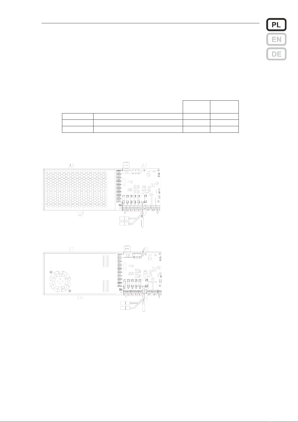
Wersje zasilaczy 1.5 –5.5 A
Widok bloku zasilacza
ZSPM-75
Opis elementów bloku zasilacza ZSPM-75 i ZSPM-150
Nr
Opis
Oznaczenie
Zalecany typ i przekrój
przewodu
1
Złącze do podłączenia zasilania
L, N,
przewód 3 żyłowy
0.75…1.5 mm2*1)
2
Przewody do podłączenia baterii
*3)
3
Sonda temperaturowa
4
Złącze odbioru 1
OUT 1
przewód 2 żyłowy
1.5 lub 2.5 mm2 *1)
5
Złącze odbioru 2
OUT 2
6
Wyjście sygnału uszkodzenia zbiorczego
GEN FLT
przewód 2 żyłowy
1x2x0.8 mm2 *2)
7
Wyjście sygnału uszkodzenia zasilania sieciowego
MAINS FLT
8
Wejście sygnału uszkodzenia zewnętrznego
EXT FLT
9
Dioda LED sygn. wewnętrznej - zielona
MAINS
10
Dioda LED sygn. wewnętrznej - żółta
BAT
11
Złącze do podłączenia diod sygnalizacyjnych
Z201
fabryczna wiązka z
pakietem LED
12
Złącze do podłączenia czujnika otwartych drzwi
Z204
fabrycznie założona zwora
13
Wejście sygnalizacji z pakietu wyjść dodatkowych
J201
*1) Połączenie należy wykonać przewodem ognioodpornym HDGs.
*2) Połączenie należy wykonać kablami sygnalizacji pożaru do układania na stałe YnTKSY
*3) Połączenie wykonywane przewodami dostarczonymi przez producenta zasilacza.
Instrukcja obsługi ZSP100 0658.00.95-06.0 6/30
Uwagi
•Dla każdego z wyjść sygnałów o uszkodzeniu, dostępne są 3 styki przekaźnika. Rysunek opisu złącza
przekaźników wskazuje na układ styków przy braku zasilania (przekaźnik niewzbudzony).
•Wejście sygnału uszkodzenia zewnętrznego połączone jest swoim zaciskiem (-) z ujemnym biegunem baterii
(B-). Wygenerowanie sygnalizacji uszkodzenia wymaga podania 0 V (zwarcia). W tym stanie między zaciskami
(+) i (-) wejścia sygnalizacji przepływa prąd o wartości około 0.25 mA.
•Jeśli szafka zasilacza ma być wyposażona w sygnalizację otwartych drzwi, w miejsce założonej fabrycznie
zwory na złączu Z204 należy dołączyć wtyczkę czujnika (tzw. tamper).
•Jedynymi elementami, które mogą być wymieniane przez użytkownika są bezpieczniki topikowe opisane
w tabeli poniżej. Dopuszczalna jest wymiana bezpieczników jedynie z zachowaniem ich wartości i szybkości
działania.
Dane bezpieczników
Wszystkie bezpieczniki w rozmiarze 5×20
ZSPM-75
ZSPM-150
B201
Obwód zasilania sieciowego (zwłoczny T)
4 AT
6.3 AT
B101, B102
Obwody wyjściowe (szybki F)
3.15 AF
6.3 AF
B103
Obwód akumulatora (szybki F)
6.3 AF
8 AF
Wersje zasilaczy 7.5 –12 A
Widok bloku zasilacza ZSPM-200
Widok bloku zasilacza ZSPM-320
Instrukcja obsługi ZSP100 0658.00.95-06.0 7/30
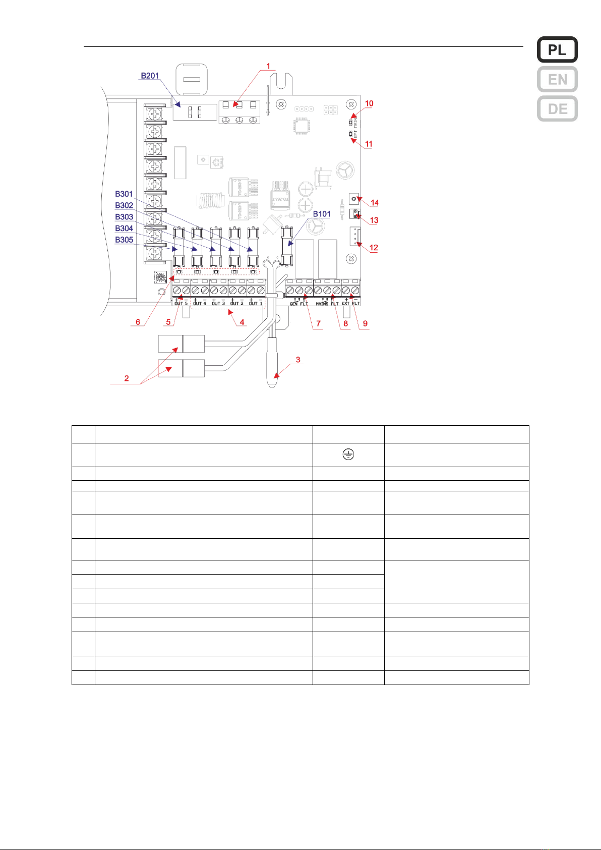
Widok pakietu sterowania
bloków zasilaczy ZSPM-200 i
ZSPM-320
Opis elementów bloku zasilacza ZSPM-200 i ZSPM-320
Nr
Opis
Oznaczenie
Zalecany typ i przekrój przewodu
1
Złącze do podłączenia zasilania
L, N,
przewód 3 żyłowy
0.75…1.5 mm2*1)
2
Przewody do podłączenia baterii
*3)
3
Sonda temperaturowa
4
Złącza odbiorów 1, 2, 3, 4
OUT 1…4
przewód 2 żyłowy
1.5 lub 2.5 mm2 *1)
5
Złącze odbioru 5
OUT 5
przewód 2 żyłowy
2.5 lub 4 mm2 *1)
6
Diody sygnalizacyjne LED przepalenia
bezpieczników wyjść 1…5
7
Wyjście sygnału uszkodzenia zbiorczego
GEN FLT
przewód 2 żyłowy
1x2x0.8 mm2*2)
8
Wyjście sygnału uszkodzenia zasilania sieciowego
MAINS FLT
9
Wejście sygnału uszkodzenia zewnętrznego
EXT FLT
10
Dioda LED sygn. wewnętrznej - zielona
MAINS
11
Dioda LED sygn. wewnętrznej - żółta
BAT
12
Złącze do podłączenia diod sygnalizacyjnych
Z306
fabryczna wiązka z pakietem
LED
13
Złącze do podłączenia czujnika otwartych drzwi
Z202
fabrycznie założona zwora
14
Wejście sygnalizacji z pakietu wyjść dodatkowych
J210
*1) Połączenie należy wykonać przewodem ognioodpornym HDGs.
*2) Połączenie należy wykonać kablami sygnalizacji pożaru do układania na stałe YnTKSY
*3) Połączenie wykonywane przewodami dostarczonymi przez producenta zasilacza.
Uwagi
•Dla każdego z wyjść sygnałów o uszkodzeniu, dostępne są 3 styki przekaźnika. Rysunek opisu złącza
przekaźników wskazuje na układ styków przy braku zasilania (przekaźnik niewzbudzony).
•Wejście sygnału uszkodzenia zewnętrznego połączone jest swoim zaciskiem (-) z ujemnym biegunem baterii
(B-). Wygenerowanie sygnalizacji uszkodzenia wymaga podania 0V (zwarcia). W tym stanie między zaciskami
(+) i (-) wejścia sygnalizacji przepływa prąd o wartości około 0.25 mA.
Instrukcja obsługi ZSP100 0658.00.95-06.0 8/30
•Jeśli szafka zasilacza ma być wyposażona w sygnalizację otwartych drzwi, w miejsce założonej fabrycznie
zwory na złączu Z202 należy dołączyć wtyczkę czujnika (tzw. tamper).
•Jedynymi elementami, które mogą być wymieniane przez użytkownika są bezpieczniki topikowe opisane
w tabeli poniżej. Dopuszczalna jest wymiana bezpieczników jedynie z zachowaniem ich wartości i szybkości
działania.
Dane bezpieczników
Wszystkie bezpieczniki w rozmiarze 5×20
ZSPM-200
ZSPM-320
B201
Obwód zasilania sieciowego (zwłoczny T)
6.3 AT
6.3 AT
B101
Obwód akumulatora (szybki F)
10 AF
16 AF
B301…B304
Obwody wyjściowe (szybki F)
2 AF
2 AF
B305
Obwody wyjściowe (szybki F)
10 AF
16 AF
Pierwsze uruchomienie
Jeśli wszystkie podłączenia wykonane zostały poprawnie, po załączeniu zasilania sieciowego stan
sygnalizacji powinien być zgodny ze wskazanym w poniższej tabeli w kolumnie Poprawne uruchomienie.
Inna sygnalizacja wskazuje na wystąpienie jednego z błędów opisanych w dodatku do instrukcji.
Przed oddaniem zasilacza do użytkowania należy wykonać dodatkowo dwa testy.
Test podtrzymania.
Odłączyć zasilanie sieciowe wyłącznikiem instalacyjnym. Zasilacz powinien przejść do trybu pracy
bateryjnej utrzymując napięcie na swoich obu wyjściach. Sprawdzenia można dokonać dowolnym
próbnikiem np. woltomierzem lub przy użyciu odpowiedniej żarówki.
Jeżeli odłączenie zasilania zostało wykonane przez wyjęcie bezpiecznika B201, stan ten może
zostać rozpoznany dopiero po 10 min. Przekaźnik GEN FLT zareaguje z opóźnieniem 5 s.
Test obecności baterii.
Przy zasilaczu pracującym z sieci należy przerwać obwód akumulatora przez odłączenie jednego
z jego przewodów. Stan ten zostanie wykryty przy najbliższym teście, co może trwać do 10 min.
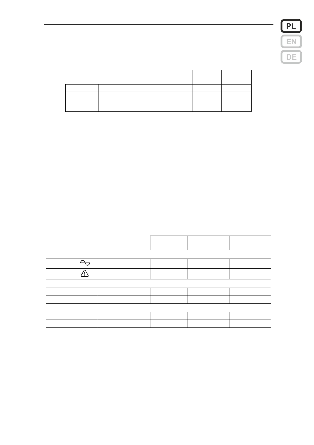
Sygnalizacja w czasie testów
Poprawne
uruchomienie
Test
podtrzymania
Test obecności
baterii
Sygnalizacja świetlna na drzwiach szafki
230VAC lub
zielona dioda LED
świeci
pulsuje
świeci
ALARM lub
żółta dioda LED
zgaszona
świeci
świeci
Sygnalizacja świetlna na płycie PCB zasilacza ZSPM
MAINS
zielona dioda LED
świeci
zgaszona
świeci
BAT
żółta dioda LED
zgaszona
zgaszona
pulsuje *1)
Sygnalizacja przekaźnikowa
MAINS FLT
Uszkodzenie sieci
wzbudzony
niewzbudzony
wzbudzony
GEN FLT
Uszkodzenie zbiorcze
wzbudzony
niewzbudzony
niewzbudzony
*1) Jeżeli bateria będzie odłączona dłużej niż 12 min., dioda BAT zostanie zapalona na stałe.
W czasie przeprowadzania testów należy dodatkowo sprawdzić, czy sygnał o uszkodzeniu GEN FLT
jest skutecznie doprowadzony do centrali sygnalizacji pożarowej.
Uwagi do pracy i obsługi zasilacza
•Zasilacze po zainstalowaniu wymagają jedynie bieżącego nadzoru związanego z ewentualnymi uszkodzeniami,
które mogą wystąpić w trakcie eksploatacji urządzenia.
•Napięcia wyjściowe jak również progi sygnalizacji ustawione są fabrycznie.
•Nie wolno ze sobą łączyć ujemnego bieguna baterii (B-) z ujemnym biegunem wyjść OUT1 i OUT2 (-) dla wersji
prądowych 1.5 ÷ 5.5 A oraz z ujemnym biegunem wyjść OUT1 … OUT5 (-) dla wersji prądowych 7.5 ÷ 12 A
•Bateria akumulatorów jest dołączana przez zasilacz tylko przy obecnym zasilaniu sieciowym i tylko
w przypadku, gdy jej napięcie jest wyższe od 21.6 V. Jeżeli bateria jest uszkodzona (napięcie poniżej 10 V) nie
Instrukcja obsługi ZSP100 0658.00.95-06.0 9/30
zostanie przez zasilacz zauważona. Dla napięć pośrednich uruchamiana jest sygnalizacja ostrzegawcza
w postaci krótkich błysków diody ALARM, lecz sama bateria w dalszym ciągu nie zostanie dołączona.
•W trybie pracy bateryjnej, przy braku zasilania sieciowego, po rozładowaniu baterii do 21 V jest ona odłączana
przez Rozłącznik Głębokiego Rozładowania (RGR). Nie wolno jednak w sposób długotrwały pozostawiać baterii
w tym stanie, gdyż w dalszym ciągu zasilacz pobiera pewien minimalny prąd na potrzeby własne, co może
doprowadzić do jej samoistnego dalszego rozładowania i nie pozwolić na jej dołączenie po powrocie zasilania
sieciowego.
•Jeżeli przewiduje się pozostawienie układu zasilacza na długi czas bez zasilania sieciowego, to należy
odłączyć baterię akumulatorów od zasilacza. Pozostawienie dołączonej baterii może doprowadzić do jej
głębokiego rozładowania i w konsekwencji do jej uszkodzenia.
•Żywotność akumulatorów wyraźnie spada ze wzrostem temperatury otoczenia. Wzrost temperatury o każde
8÷10°C skraca żywotność o połowę.
•Zgodnie z zaleceniami CNBOP-PIB i VdS akumulatory powinny podlegać wymianie bez względu na ich stan po
4 latach eksploatacji.
•Zasilacze należy poddać przeglądowi raz w roku, wykonując testy opisane w części Pierwsze uruchomienie.
Postępowanie z opakowaniami, zużytymi wyrobami i akumulatorami
Opakowanie wyrobu wykonane jest z materiałów, które mogą zostać poddane recyklingowi (drewno,
papier, tektura, tworzywa sztuczne). Niepotrzebne opakowania należy posegregować i przekazać
odbiorcy odpadów.
To oznaczenie umieszczone na produkcie wskazuje, że produktu po upływie czasu użytkowania nie
należy usuwać z odpadami komunalnymi, lecz należy go przekazać do punktu odbioru zużytego
sprzętu elektronicznego. Zużyte akumulatory stanowią odpad niebezpieczny i muszą zostać
poddane utylizacji. Przyczyni się to do uniknięcia szkodliwego wpływu na zdrowie ludzi i środowisko
naturalne wskutek niekontrolowanego usuwania odpadów.

Instrukcja obsługi ZSP100 0658.00.95-06.0 10/30
Dodatek
Uwaga: „prostownik” rozumiany jest jako zasilacz sieciowy z funkcją ładowania baterii akumulatorów.
Sygnalizacja świetlna, na drzwiach szafki zasilacza.
230VAC lub
zielona dioda LED
0
- brak zasilania sieciowego, bateria odłączona (stan beznapięciowy)
1
- obecne zasilanie sieciowe, prostownik sprawny
0/1 pulsowanie
- praca bateryjna: brak sieci lub uszkodzony prostownik *1)
ALARM lub
żółta dioda LED
0
- brak uszkodzeń
1
- praca bateryjna: brak zasilania sieciowego lub uszkodzony prostownik *1)
- brak baterii, lub dołączona bateria ma napięcie niższe od 10 V - RGR jest wył.
- zbyt wysoka rezystancja obwodu baterii lub przepalony bezpiecznik baterii (>250 mΩ)
- przepalony bezpiecznik wyjściowy
- przepalony bezpiecznik w module wyjść dodatkowych ZSP100-OUT6 lub ZSP101-OUT6
(jeśli dołączono)
- napięcie baterii poniżej 22 V przy obecnym zasilaniu sieciowym *2)
0/1 pulsowanie
- alarm zewnętrzny lub alarm wewnętrzny (czujnik otwartych drzwi szafki, „tamper”)
0/1 krótkie błyski
- rozpoznano baterię (U>10 V) lecz ma zbyt niskie napięcie (U<21.6 V) - RGR jest
wyłączony
*1) Uszkodzenie prostownika jest rozpoznawane najdalej po 10 min. od wystąpienia zdarzenia (sprawdzenie
wykonywane jest jednocześnie z pomiarem rezystancji obwodu baterii).
*2) Stan taki może wystąpić po powrocie zasilania sieciowego, gdy ładowanie baterii dopiero się rozpoczęło.
Sygnalizacja świetlna na płycie zasilacza ZSPM (pakiet pcb)
MAINS
Kolor
zielony
0
brak zasilania sieciowego
1
obecne zasilanie sieciowe, prostownik sprawny
0/1 krótkie błyski
obecne zasilanie sieciowe, prostownik uszkodzony *1)
BAT
Kolor żółty
0
bateria poprawna
1
rezystancja obwodu baterii >250 mΩ (w tym brak baterii lub przepalony
bezpiecznik baterii) *2)
0/1 pulsowanie
bateria została odłączona lub bezpiecznik baterii został przepalony *3)
*1) Uszkodzenie prostownika jest rozpoznawane najdalej po 10 min od wystąpienia zdarzenia (sprawdzenie wykonywane jest
jednocześnie z pomiarem rezystancji obwodu baterii).
*2) Pomiar rezystancji obwodu bateryjnego, w tym wykrycie odłączenia baterii i przepalenia się bezpiecznika bateryjnego,
wykonywany jest co 10 min. Pierwszy wykryty błąd zmniejsza ten czas do 1 min. Po trzykrotnym, powtarzającym się raz za razem
przekroczeniu, dioda BAT zapala się światłem ciągłym i jedocześnie wystawiany jest sygnał przekaźnikowy o uszkodzeniu
zbiorczym GEN FLT. Tak więc całkowity czas wygenerowania alarmu wynosi 12 min. Każdy poprawny pomiar przywraca 10
minutowy okres. Zadaniem tego mechanizmu jest zmniejszenie ryzyka pojawienia się przypadkowej sygnalizacji błędu.
*3) Do uruchomienia tej sygnalizacji; odłączenia baterii i przepalenia bezpiecznika bateryjnego, wystarcza jednokrotny pomiar
opisany w *2). Pozwala to na sprawdzenie układu np. w celach serwisowych bez generowania sygnału o błędzie GEN FLT o ile
przywrócono stan poprawny w ciągu 2 min.
Tabela 9. Sygnalizacja przekaźnikowa (0 - przekaźnik niewzbudzony, 1 - przekaźnik wzbudzony)
MAINS FLT
Uszkodzenie sieci
0
- brak zasilania sieciowego (tylko sieć, nie reaguje na uszkodzenie prostownika)
1
- obecne zasilanie sieciowe, prostownik sprawny
GEN FLT
Uszkodzenie zbiorcze
0
- zawsze, gdy dioda ALARM jest zapalona, pulsuje lub błyska *1) *2)
1
- brak uszkodzeń
*1) Uszkodzenie prostownika jest rozpoznawane najdalej po 10 min od wystąpienia zdarzenia (sprawdzenie
wykonywane jest jednocześnie z pomiarem rezystancji obwodu baterii).
*2) Przy zaniku i powrocie zasilania sieciowego sygnalizacja uruchamiana jest z 5 s zwłoką.

User Manual ZSP100 0658.00.95-06.0 11/30
MERAWEX Sp. z o.o.
Toruńska 8
44-122 Gliwice
Poland
tel. +48 32 23 99 400
fax +48 32 23 99 409
[email protected]om.pl
http://www.merawex.com.pl
USER MANUAL
Power supplies for fire indication, heat and smoke control systems, fire protection and
fire automation devices according to EN 54-4:1997 + AC:1999 + A1:2002 + A2:2006
and EN 12101-10:2005 + AC:2007
ZSP100-1.5A-07, ZSP100-1.5A-18, ZSP100-2.5A-07, ZSP100-2.5A-18
ZSP100-4.0A-07, ZSP100-4.0A-18, ZSP100-4.0A-40
ZSP100-5.5A-07, ZSP100-5.5A-18, ZSP100-5.5A-40
ZSP100-7.5A-18, ZSP100-7.5A-40, ZSP100-7.5A-75
ZSP100-10A-18, ZSP100-10A-40, ZSP100-10A-75
ZSP100-12A-18, ZSP100-12A-40, ZSP100-12A-75
03.03.2020
Certification of constancy of performance CNBOP-PIB No. 1438-CPR-0454
Declaration of performance No. DWU-MX-08
Certificate of admittance CNBOP-PIB No. 2582/2016
Warnings
Please read all these tips and regulations. Mistakes in their observance may cause damage, electric
shock, fire or serious injury.
▪It is forbidden to carry and transport the device with mounted and connected batteries.
This can cause severe internal faults and can lead to the loss of operation safety.
▪Installation and connections can be made only when batteries removed.
▪When connecting batteries that may pose a threat due to high energy level, pay special
attention to the compatibility of their polarity with the description on the connector
▪Do not block ventilation openings. Provide a free space of at least 10 cm at the sides of the
device, enabling its proper ventilation. Otherwise, it can lead to damage of the device or early
battery deterioration.
▪Please, install the device in a place where it is not exposed to direct sunlight.
▪The device must be powered from the mains with a protective earthing terminal.
▪Before starting the device, please, check the quality of all connections.
▪The device may interfere with operation of sensible radio and television equipment
located nearby.
▪The device may be operated only by authorized and trained personnel.
▪The device must be serviced by servicemen of the manufacturer or specialized service
companies authorized by the manufacturer.
User Manual ZSP100 0658.00.95-06.0 12/30
Technical description
The power supplies are designed to supply uninterruptible power to 24 V fire protection devices,
meeting the requirements of the EN 54-4 + AC + A1 + A2 and EN 12101-10 + AC. The source of
backup power is two 12 V lead-acid VRLA type batteries. The power supplies are designed for wall
mounting. All nineteen versions made in four types of cabinets are described in the table below.
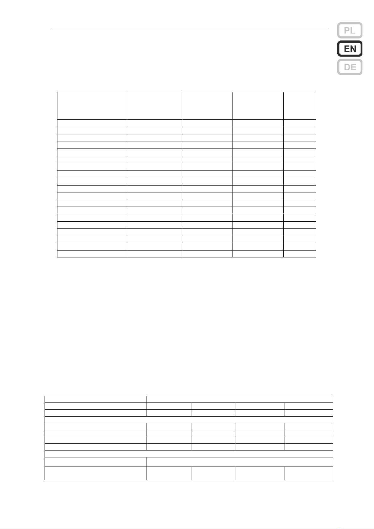
Versions of ZSP100
Power supply in cabinet
Power supply
block
Max output
current
Batteries
Cabinet
ZSP100-1.5A-07
ZSPM-75-05
1.5 A
7…9 Ah
7
ZSP100-1.5A-18
ZSPM-75-10
1.5 A
7…20 Ah
18
ZSP100-2.5A-07
ZSPM-75-05
2.5 A
7…9 Ah
7
ZSP100-2.5A-18
ZSPM-75-10
2.5 A
7…20 Ah
18
ZSP100-4.0A-07
ZSPM-150-05
4.0 A
7…9 Ah
7
ZSP100-4.0A-18
ZSPM-150-10
4.0 A
7…20 Ah
18
ZSP100-4.0A-40
ZSPM-150-20
4.0 A
17…45 Ah
40
ZSP100-5.5A-07
ZSPM-150-05
5.5 A
7…9 Ah
7
ZSP100-5.5A-18
ZSPM-150-10
5.5 A
7…20 Ah
18
ZSP100-5.5A-40
ZSPM-150-20
5.5 A
17…45 Ah
40
ZSP100-7.5A-18
ZSPM-200-18
7.5 A
7…20 Ah
18
ZSP100-7.5A-40
ZSPM-200-33
7.5 A
17…45 Ah
40
ZSP100-7.5A-75
ZSPM-200-33
7.5 A
17…75 Ah
75
ZSP100-10A-18
ZSPM-320-18
10 A
7…20 Ah
18
ZSP100-10A-40
ZSPM-320-33
10 A
17…45 Ah
40
ZSP100-10A-75
ZSPM-320-33
10 A
17…75 Ah
75
ZSP100-12A-18
ZSPM-320-18
12 A
7…20 Ah
18
ZSP100-12A-40
ZSPM-320-33
12 A
17…45 Ah
40
ZSP100-12A-75
ZSPM-320-33
12 A
17…75 Ah
75
Completion of power supply:
•power supply cabinet with power supply
block inside
•glands: DW16-RM 1 pc., DW20-RM 3 pcs.
Optional equipment:
•4 cabinet mounting brackets with wall
distance shoulder
•module of 6 auxiliary outputs type
ZSP100-OUT6 or ZSP101-OUT6 *)
•tamper switch with cables
•additional glands
*) ZSP100-OUT6 occurs with specific fuse values, e.g. ZSP100-OUT6-1.0AF indicates the use of fast (F) 1 A (1.0 A) fuses.
ZSP101-OUT6 allows the use of any fuse from 0.2 A to 10 A, according to the user's needs.
Cabinets, in the upper part and on the left side, include ready, but still closed holes for the glands
and also have a rectangular cut-out from the wall side, to pass electrical wires. Before installing the
cabinets, please choose cable routing, remove the appropriate hole covers by breaking them out and
mount the required amount of glands in right places.
Overall dimensions and mounting
Cabinet
7
18
40
75
Overall dimensions (W x H x D) [mm]
340 x 250 x 80
395 x 356 x 96
455 x 356 x 187
555 x 406 x 187
Mounting
- inside cabinet (W x H) [mm]
276 x 182
350 x 282
410 x 282
510 x 332
- when using clips (W x H) [mm]
276 x 270
350 x 370
410 x 370
510 x 420
Weight without battery bank –max.
3.1 kg
4.9 kg
7.6 kg
11.4 kg
Weight with battery bank –max.
8.4 kg
17.2 kg
36.6 kg
57.4 kg
Holes for glands
- in upper side
6x DW20-RM, 1x DW16-RM
- in left side
3x DW20-RM,
1x DW16-RM
6x DW20-RM,
1x DW16-RM
6x DW20-RM,
1x DW16-RM
6x DW20-RM,
1x DW16-RM

User manual ZSP100 0658.00.95-06.0 13/30
The view of the power supply and the
spacing of holes for its fixing (below) on
the example of the cabinet 18
On the cabinet's door, the following
markings may be used interchangeably:
230V AC or
ALARM or
17.3
350
282
350
370
8
6.5
12
6.5
The cabinet must be mounted to the wall with 4 steel screws. Please do not use plastic raw plugs.
Prior to installation, it is advisable to remove the power supply block by unscrewing two bolts at the
bottom, light deflection and sliding the whole block down. After mounting the cabinet, please mount the
block of the power supply again.
Basic electrical and environmental parameters
Nominal voltage *1)
110 / 230V +10% -15%
Nominal output voltage *2)
27.1 V
Output voltage regulation *3)
21.0…28.8 V
Quiescent current consumption from battery
•max 17 mA (versions 1.5 –5.5 A)
•max 25 mA (versions 7.5 –12 A)
Efficiency at nominal load and when battery charged
89%
Max. resistance of battery circuit (versions 1.5 –5.5 A) *4)
250 mΩ
Max. resistance of battery circuit (versions 7.5 –12 A) *4)
100 mΩ (150 mΩ for cabinet 18)
Number of batteries supervised
2
Number of outputs protected with separate fuses
•2 (versions 1.5 –5.5 A)
•5 (versions 7.5 –12 A)
Operation temperature
-5…+55°C
Ingress protection EN 60529:1991 + A1:2000
IP 42
Functional / Environmental class EN 12101-10:2005 + AC:2007
A / 2
Protection class
EN 60950-1:2006 + A11:2009 + A1:2010 + A12:2011 + A2:2013
I
*1) To use mains voltage 110 V in ZSP100 power supplies consisting of power module ZSM-150, the mains voltage switch
should be switched to 115 V; it is not needed for ZSP100 versions including ZSPM-75, ZSPM-200, ZSPM-320
*2) It concerns floating operation mode at 25C
*3) The range includes a voltage between the voltage discharge of the battery (the end of the battery cycle) to
the voltage of bulk charging.
User manual ZSP100 0658.00.95-06.0 14/30
*4) A resistance value of the battery circuit at which the fault indication is activated.
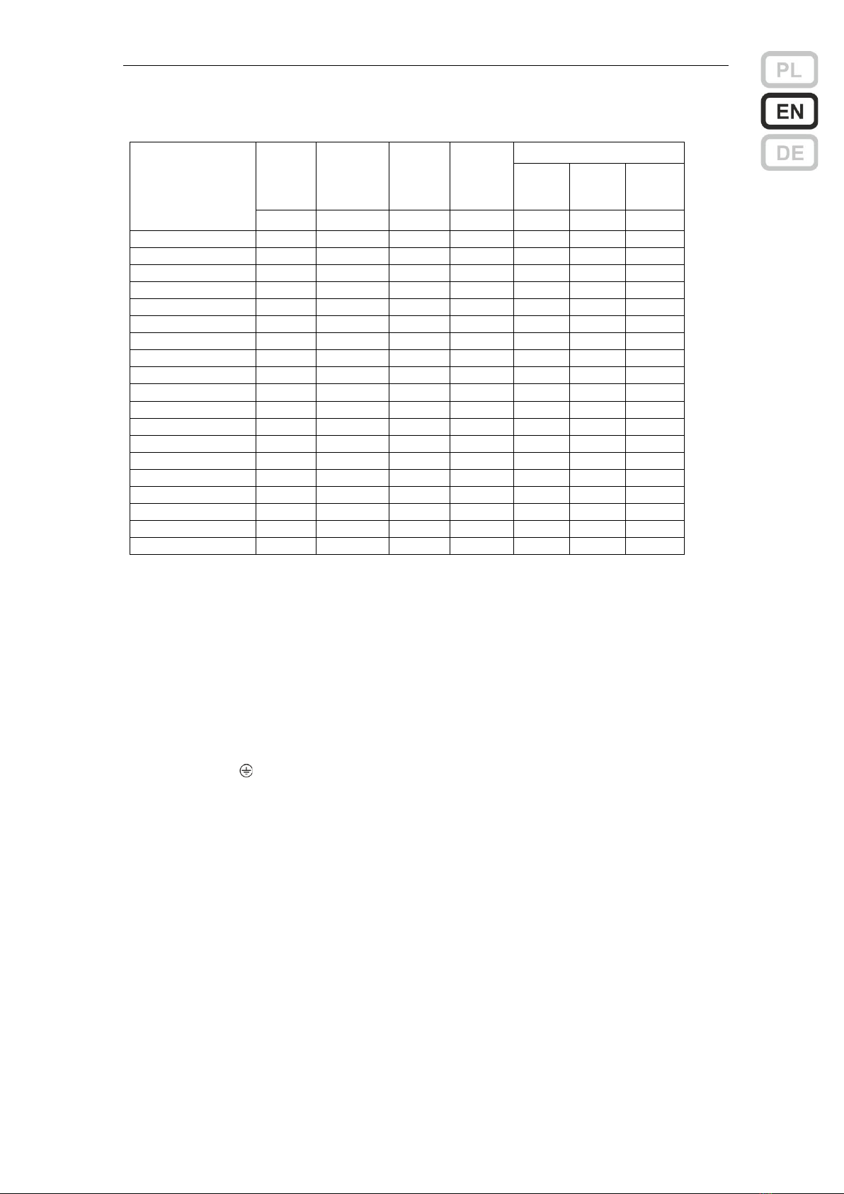
Current parameters of power supplies
Type
Battery
Charging
current
Imax_b
(max
output
current)
Imax_a
EN 54-4
Imax_a EN 12101-10
72 h
30 h
4 h
Ah
A
A
A
A
A
A
ZSP100-1.5A-07
9
0.5
1.5
1.1
0.08
0.21
1.1
ZSP100-1.5A-18
20
1.0
1.5
0.6
0.20
0.49
0.7
ZSP100-2.5A-07
9
0.5
2.5
2.1
0.08
0.21
1.3
ZSP100-2.5A-18
20
1.0
2.5
1.6
0.19
0.49
1.7
ZSP100-4.0A-07
9
1.0
4.0
3.6
0.08
0.21
1.3
ZSP100-4.0A-18
20
1.0
4.0
3.1
0.19
0.49
3.0
ZSP100-4.0A-40
45
2.0
4.0
2.0
0.46
1.13
2.3
ZSP100-5.5A-07
9
0.5
5.5
5.1
0.08
0.20
1.3
ZSP100-5.5A-18
20
1.0
5.5
4.6
0.19
0.49
3.0
ZSP100-5.5A-40
45
2.0
5.5
3.5
0.46
1.13
3.8
ZSP100-7.5A-18
20
1.8
7.5
6.6
0.20
0.51
3.11
ZSP100-7.5A-40
45
3.3
7.5
5.6
0.49
1.21
5.56
ZSP100-7.5A-75
75
3.3
7.5
4.3
0.84
2.04
4.26
ZSP100-10A-18
20
1.8
10
9.1
0.19
0.50
3.03
ZSP100-10A-40
45
3.3
10
8.1
0.49
1.20
7.21
ZSP100-10A-75
75
3.3
10
6.8
0.83
2.04
6.76
ZSP100-12A-18
20
1.8
12
11.1
0.19
0.49
2.96
ZSP100-12A-40
45
3.3
12
10.1
0.48
1.20
7.16
ZSP100-12A-75
75
3.3
12
8.8
0.83
2.03
8.76
Remarks:
•designations Imax_a and Imax_b compliant with EN 54-4 standard.
•the current Imax_b can be taken entirely from the OUT 1 output or as the sum of the currents of both OUT-
1 and OUT-2 outputs (applies to versions 1.5 ÷ 5.5 A)
•Imax_b current can be taken entirely from the OUT 5 output or as a sum of currents from all 5 outputs of
the power supply (applies to versions 7.5 ÷ 12 A)
•the Imax_a currents specific to EN 12101-10 are specified for the nominal capacity of the batteries (as in
the table). When using batteries with smaller capacities, please contact the power supply manufacturer to
determine the corrected values
Installation and connection
The power supply must be connected to a fixed installation with the use of protective cable
connected to terminal and taking into account the markings L and N. It is recommended to include a
surge protection system in the installation. The mains voltage should not be switched off by means of
the main fire protection power switch. It is required to mount in the power circuits, outside the power
supply, an installation breaker of the nominal current of at least 3 A (for versions 1.5 ÷ 5.5 A) and 6 A
(for versions 7.5 ÷ 12 A). The power area and the switch itself should be marked with red and a number
of the power supply. One circuit breaker should protect only one power supply.
Batteries should be connected after making all the other connections (output voltage of 24 V and
indication circuits) and connecting a LED harness on the housing plus possibly the tamper switch. After
placing the batteries on the bottom of the cabinet, please place the temperature probe between them in
such way, that it is in contact with walls of both batteries and then connect the cables to the appropriate
poles: red cable to the pole (+) of one battery and the black cable to the pole (-) of the other. As a last,
please make the connection between two batteries using cable provided with the power supply. When
disconnecting the batteries, the order is reversed.

User manual ZSP100 0658.00.95-06.0 15/30
Power supply versions 1.5 ÷ 5.5 A
View of power supply block
ZSPM-75
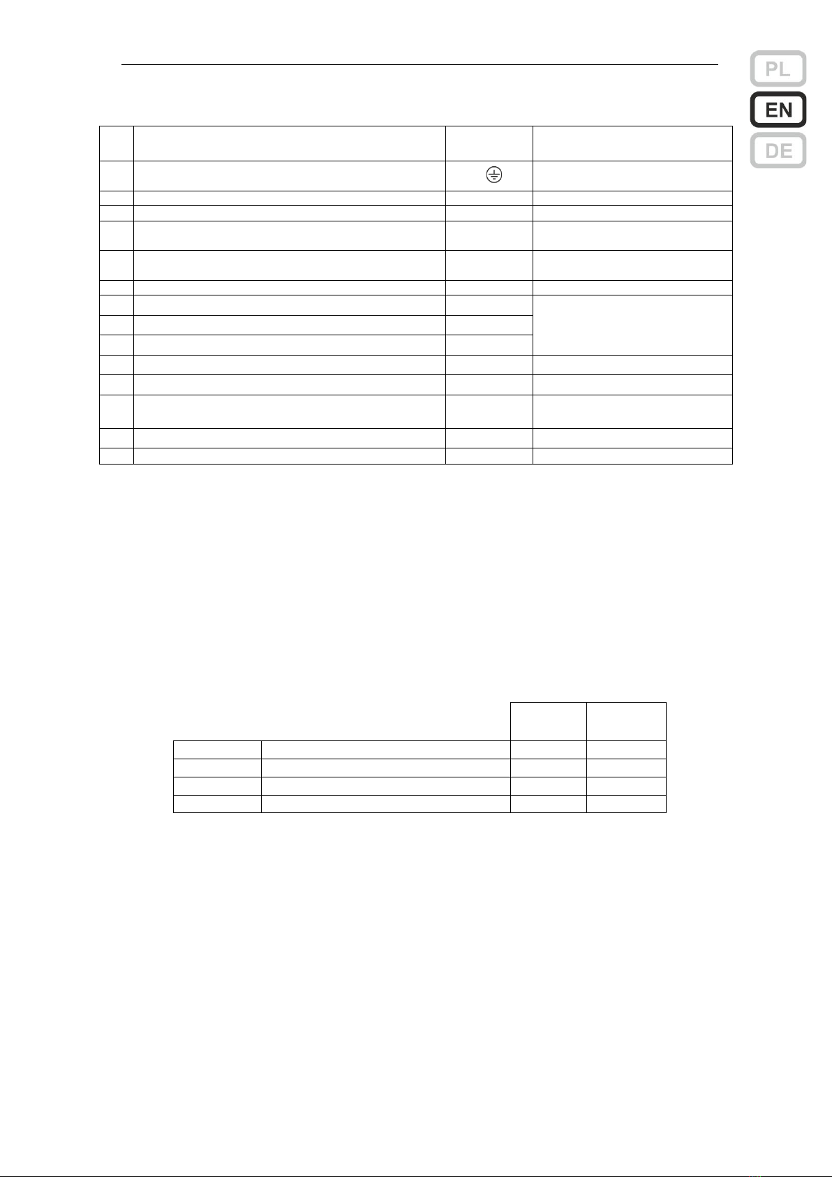
Description of chosen components on ZSPM-75 and ZSPM-150 module
No.
Description
Marking
Recommended type and cable diameter
1
Mains power connector
L, N,
3 solid core cable 0.75…1.5 mm2 *1)
2
Cables for connecting batteries
*3)
3
Temperature probe
4
Load 1 connector
OUT 1
twin solid core cable 1 or 2.5 mm2 *1)
5
Load 2 connector
OUT 2
6
Output of general fault signal
GEN FLT
twin solid core cable 1x2x0.8 mm2 *2)
7
Output of mains fault signal
MAINS FLT
8
Input of external fault signal
EXT FLT
9
LED of internal indication - green
MAINS
10
LED of internal indication - yellow
BAT
11
Connector for indication diodes
Z201
Factory bundle with LED package
12
Connector for tamper switch
Z204
Factory installed jumper
13
Input for indication from packet of additional
outputs
J201
*1) The connection should be made with flame retardant halogen free cable.
*2) The connection should be made with telecom flame retardant cable for permanent installation
*3) Connection made with cables provided by the power supply manufacturer.
Notes
•There are 3 relay contacts available for each of the fault indication outputs. The figure describing the connector
of the relays shows an arrangement of terminals when the mains is off (relay de-energized).
•The input of an external fault is connected with its terminal (-) to the negative pole of the battery (B-). Detection
of the voltage 0 V (short circuit) will generate fault indication. In this state, the current of approx. 0.25 mA flows
between the terminals (+) and (-) of the input.
•If the power supply cabinet is to be equipped with the tamper switch, please connect the plug of the sensor
(tamper) in a place of the factory set jumper on the connector Z204.
•The only components that can be exchanged by a user are fuses described in the table below. It is permissible
to replace the fuses only with the ones of the same value and speed.
User manual ZSP100 0658.00.95-06.0 16/30
Fuses ratings
All fuses in size 5x20
ZSPM-75
ZSPM-150
B201
Mains circuit (slow-blow T)
4 AT
6.3 AT
B101, B102
Output circuits (fast-blow F)
3.15 AF
6.3 AF
B103
Battery circuit (fast-blow F)
6.3 AF
8 AF
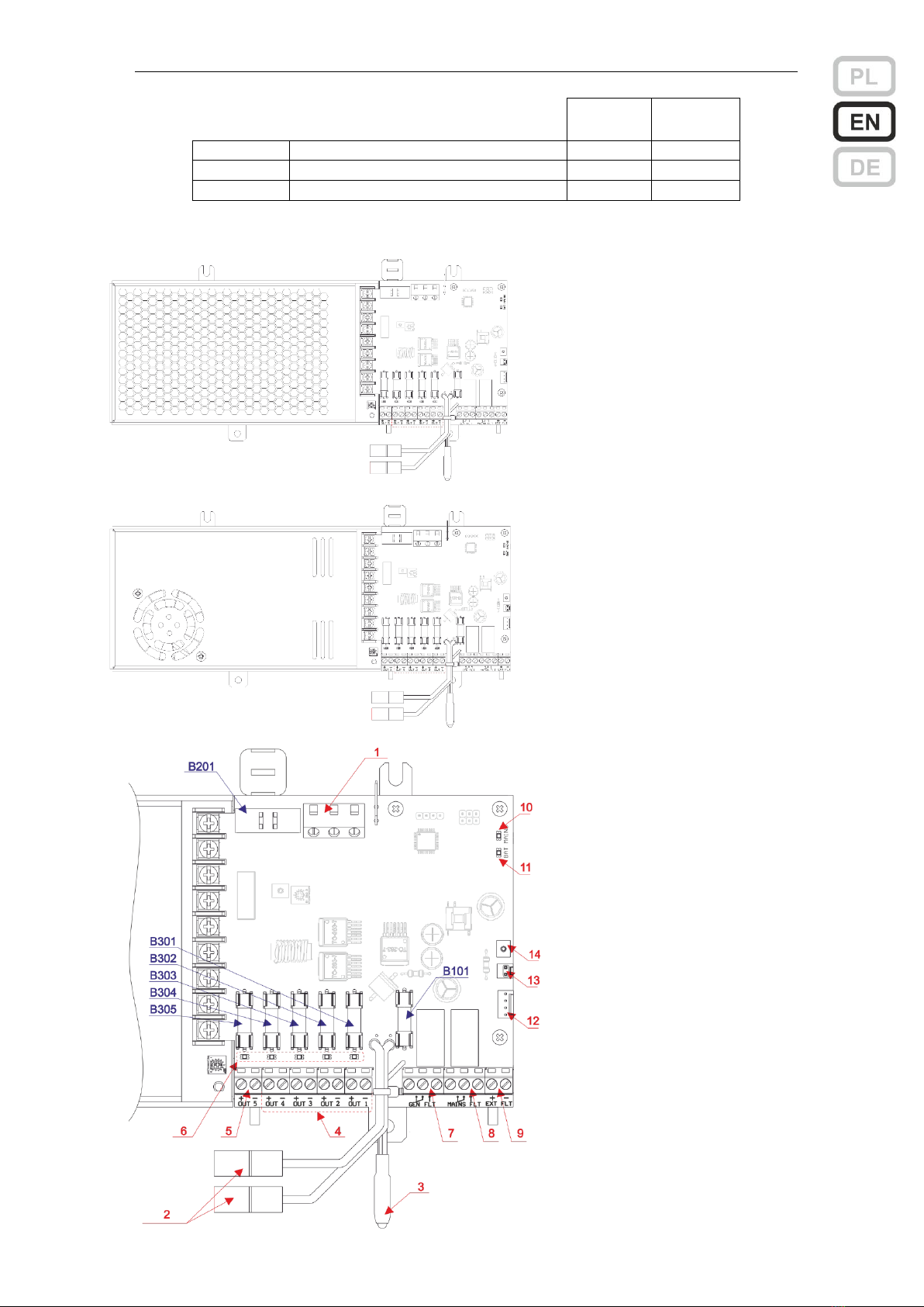
Power supply versions 7.5 ÷ 12 A
View of power supply block ZSPM-200
View of power supply block ZSPM-320
View of the ZSPM-200 and ZSPM-320
power supply block control package
User manual ZSP100 0658.00.95-06.0 17/30
Description of chosen components on ZSPM-200 and ZSPM-320 module
No.
Description
Marking
Recommended type and cable
diameter
1
Mains power connector
L, N,
3 solid core cable 0.75…1.5
mm2 *1)
2
Cables for connecting batteries
*3)
3
Temperature probe
4
Load 1, 2, 3, 4 connector
OUT 1…4
twin solid core cable
1.5 or 2.5 mm2 1)
5
Load 5 connector
OUT 5
twin solid core cable
2.5 or 4 mm2 *2)
6
LEDs for blown output fuses 1 ... 5
7
Output of general fault signal
GEN FLT
twin solid core cable
1x2x0.8 mm2 *2)
8
Output of mains fault signal
MAINS FLT
9
Input of external fault signal
EXT FLT
10
LED of internal indication - green
MAINS
11
LED of internal indication - yellow
BAT
12
Connector for indication diodes
Z306
Factory bundle with LED
package
13
Connector for tamper switch
Z202
Factory installed jumper
14
Input for indication from packet of additional outputs
J210
*1) The connection should be made with flame retardant halogen free cable.
*2) The connection should be made with telecom flame retardant cable for permanent installation
*3) Connection made with cables provided by the power supply manufacturer.
Notes
•There are 3 relay contacts available for each of the fault indication outputs. The figure describing the connector
of the relays shows an arrangement of terminals when the mains is off (relay de-energized).
•The input of an external fault is connected with its terminal (-) to the negative pole of the battery (B-). Detection
of the voltage 0 V (short circuit) will generate fault indication. In this state, the current of approx. 0.25 mA flows
between the terminals (+) and (-) of the input.
•If the power supply cabinet is to be equipped with the tamper switch, please connect the plug of the sensor
(tamper) in a place of the factory set jumper on the connector Z202.
•The only components that can be exchanged by a user are fuses described in the table below. It is permissible
to replace the fuses only with the ones of the same value and speed.
Fuses ratings
All fuses in size 5x20
ZSPM-200
ZSPM-320
B201
Mains circuit (slow-blow T)
6.3 AT
6.3 AT
B101
Battery circuit (fast-blow F)
10 AF
16 AF
B301…B304
Output circuits (fast-blow F)
2 AF
2 AF
B305
Output circuits (fast-blow F)
10 AF
16 AF
First start
If all the connections are made correctly, then after turning on the power supply, the status indication
should be in accordance with the one mentioned in the table below in the column Correct start.
Another signal indicates the occurrence of one of the errors described in the Appendix to the User
Manual.
Before using the power supply, please, perform additional two tests.
Test of power backup.
Please, disconnect the mains with the installation breaker. The power supply should switch into the
battery operation mode, retaining voltage on its both outputs. The test can be performed by any probe,
e.g. by using a voltmeter or a suitable bulb.
If disconnection of power was done by removing the fuse B201, the condition can be detected only
after 10 minutes. The GEN FLT relay will react with a delay of 5 seconds.
User manual ZSP100 0658.00.95-06.0 18/30
Test of battery presence.
When the power supply is powered with the mains, please break the circuit of the battery by
disconnecting one of the cables. This condition will be detected at the next test, which can take up to 10
minutes.
Indication during tests
Correct start
Test of power
backup
Test of battery
presence
LED indication on cabinet’s door
230V AC or
green LED
on
blinking
on
ALARM or
yellow LED
off
on
on
LED indication on PCB of ZSPM power supply
MAINS
green LED
on
off
on
BAT
yellow LED
off
off
blinking *)
Relay indication
MAINS FLT
Mains fault
Energized
de-energized
energized
GEN FLT
General fault
Energized
de-energized
de-energized
*) If the battery is disconnected for more than 12 min., the diode BAT will be permanently on.
Please check during the tests whether the fault indication GEN FLT is successfully transmitted to the
fire alarm control panel.
Notes on operation and maintenance of power supply
•The power supplies after installation only require ongoing supervision in the case of possible faults that may
occur during operation.
•Output voltages as well as indication levels are factory preset.
•Please, do not connect to each other the negative pole of the battery (B-) to the negative poles OUT1 and
OUT2 (-) for versions 1.5 ÷5.5 A and to the negative poles OUT1 …OUT5 (-) for versions 7.5 ÷12 A
•The battery bank is connected by the power supply only when the mains power is present and only when the
battery voltage is higher than 21.6 V. The battery will not be detected by the power supply if the battery is
faulty (voltage below 10 V). Warning indication (short flashes of LED ALARM) is activated for intermediate
voltages, but the battery itself still will not be connected.
•In the battery operation mode, when the mains power is out and when the battery is discharged down to 21
V, the LVDD (Low Voltage Disconnect Device) disconnects the battery. The battery should not be left in
such the state for a long time as power supply still takes some minimal current for own needs, so it can lead
to its further discharge and it might not be reconnected by the power supply after the mains power is back.
•If it is planned to leave the PSU system for a long time without mains supply, disconnect the battery
from the power supply. Leaving the battery attached may lead to its deep discharge and, in
consequence, to its damage.
•Battery life drops significantly with temperature increase. The temperature increase of every 8÷10°C
shortens the life by half.
•According to the recommendations of the CNBOP-PIB and VdS authorities, batteries should be exchanged
regardless of their state after 4 years of operation.
•The power supplies should be inspected once a year by performing the tests described in the part First
Start.
Handling packaging, used products and batteries
Product packaging is made of non-hazardous materials (wood, paper, cardboard, plastics), which can
be recycled. Packages which are no longer needed should be passed on to a waste collection station,
after they had been sorted.
This marking on the product indicates that the product after that time should not be disposed with
household waste, but should be sent to a collection point for electronic waste. Used batteries are a
hazardous waste and must be disposed of. This will help to avoid adverse effects on human health
and the environment from uncontrolled waste disposal.

User manual ZSP100 0658.00.95-06.0 19/30
Appendix
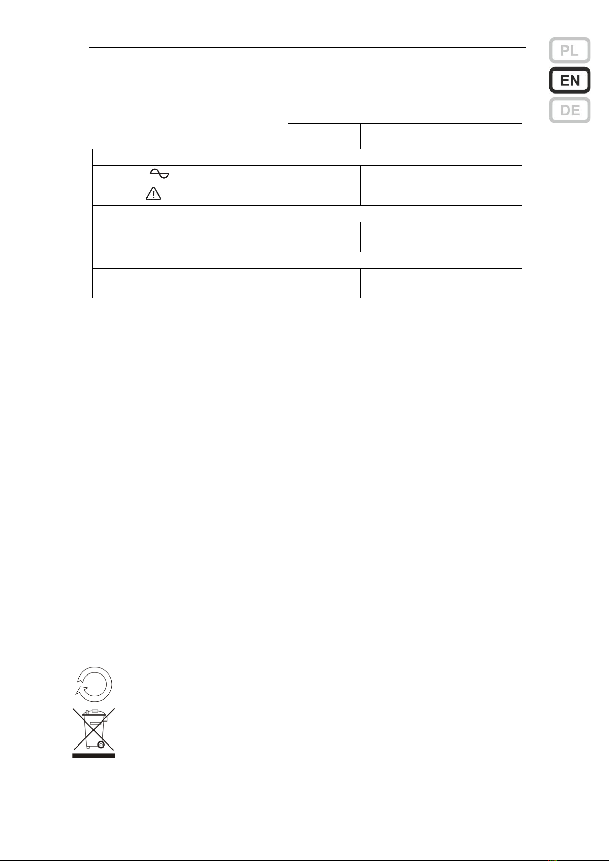
LED indication on the cabinet’s door of the power supply
230V AC or
green LED
0
- no mains power, battery disconnected (no-voltage state)
1
- mains present, power supply / charger operational
0/1 blinking
- battery operation: no mains or faulty power supply/charger *1)
ALARM or
yellow LED
0
- no faults
1
- battery operation: no mains or faulty power supply / charger *1)
- no battery, or voltage of connected battery is lower than 10 V - LVDD is
turned off
- too high resistance of battery circuit or battery fuse blown (>250 mΩ)
- output fuse blown
- blown fuse in the module of additional fuses ZSP100-OUT6 or ZSP101-OUT6 (if
connected)
- battery voltage below 22 V when mains power present *2)
0/1 blinking
- external alarm or internal alarm (tamper)
0/1 flashing
- battery recognized (U>10 V) but its voltage is too low (U<21.6 V) - LVDD remains
disconnected
*1) Power supply / charger failure is recognized at the latest after 10 minutes of the occurrence of the event (the
check is performed simultaneously with the measurement of the resistance of the battery circuit).
*2) The state can occur after the mains power is back and when battery charging just started.
LED indication on PCB of power supply ZSPM (PCB)
MAINS
green colour
0
no mains power
1
mains power present, power supply / charger operational
0/1 flashes
mains power present, power supply / charger faulty *1)
BAT
yellow colour
0
battery correct
1
resistance of battery circuit >250 mΩ (including lack of battery or
blown battery fuse *2)
0/1 blinking
battery was disconnected or battery fuse was blown *3)
*1) Power supply / charger failure is recognized at the latest after 10 minutes of the occurrence of the event (the
check is performed simultaneously with the measurement of the resistance of the battery circuit).
*2) Resistance measurements of the battery circuit, including the battery disconnection and battery fuse blow, is
performed every 10 minutes. The first detected error reduces this time to 1 min. After detecting the excess three
times, one after another, the BAT LED is on with the steady light and, in the same time, the relay indication of
the general fault GEN FLT is triggered. Thus, the total alarm time is 12 minutes. Each correct measurement
restores a 10-minute period. The purpose of this mechanism is to reduce the risk of accidental error signaling.
*3) To start this signaling; disconnecting the battery and burning the battery fuse, a single measurement described
in *2) is sufficient. This allows you to check the system (e.g. for service purposes) without generating a GEN
FLT error signal if the correct state has been restored within 2 minutes.
Relay indication (0 - relay de-energized, 1 - relay energized)
MAINS FLT
Mains fault
0
- no mains power (mains only, not reacting to power supply / charger’s fault)
1
- mains power present, power supply/charger operational
GEN FLT
General fault
0
- always, when LED ALARM is on, blinking or flashing *1) *2)
1
- no faults
*1) Power supply / charger fault is recognized at the latest after 10 minutes of the occurrence of the event (the
check is performed simultaneously with the measurement of the resistance of the battery circuit).
*2) After the mains failure and after its recovery, the indication is activated with 5 s delay.

Handbuch ZSP100 0658.00.95-06.0 20/30
MERAWEX Sp. z o.o.
Toruńska 8
44-122 Gliwice, Polen
Tel. +48 32 23 99 400
Fax +48 32 23 99 409
E-Mail: merawex@merawex.com.pl
http://www.merawex.com.pl
BEDIENUNGS- UND INSTALLATIONSANLEITUNG
Netzteile für Brandmeldeanlagen, Rauch- und Wärmeabzugsanlagen,
Brandschutzsystemen und Brandschutzautomatik gemäß EN 54-4:1997 + AC:1999 +
A1:2002 + A2:2006 und EN 12101-10:2005 + AC: 2007
ZSP100-1.5A-07, ZSP100-1.5A-18, ZSP100-2.5A-07, ZSP100-2.5A-18
ZSP100-4.0A-07, ZSP100-4.0A-18, ZSP100-4.0A-40
ZSP100-5.5A-07, ZSP100-5.5A-18, ZSP100-5.5A-40
ZSP100-7.5A-18, ZSP100-7.5A-40, ZSP100-7.5A-75
ZSP100-10A-18, ZSP100-10A-40, ZSP100-10A-75
ZSP100-12A-18, ZSP100-12A-40, ZSP100-12A-75
03.03.2020
Zertifikat der Leistungsbeständigkeit CNBOP-PIB Nr. 1438-CPR-0454
Leistungserklärung Nr. DWU-MX-08
Anerkennungsurkunde CNBOP-PIB Nr. 2582/2016
WARNHINWEISE
Lesen Sie unbedingt alle Hinweise durch. Nichtbeachtung dieser Anweisung könnte die
Beschädigung des Gerätes, Brand oder schwere Körperverletzung verursachen.
▪Es ist verboten das Gerät mit eingebauten und angeschlossenen Akkus zu bewegen oder
befördern. Es kann zu ernsten inneren Beschädigungen führen, einschließlich bis den
Verlust des sicheren Verbrauch.
▪Einbau und Anschließungen können nur ohne Akkus stattfinden.
▪Bei der Anschließung der Akkus, die mit Ihrem hohen Energieniveau eine Bedrohung
kreieren, man darf besonders auf die Verträglichkeit der Polarität mit der Beschreibung
auf dem Stecker beachten.
▪Verdecken Sie nicht die Lüftungsöffnungen. Man soll mindestens 10 cm des Freiraums
seitlich des Gerätes für ordnungsgemäße Luftzirkulation sicherstellen. Andernfalls es
kann zur Beschädigung des Gerätes oder vorzeitigem Verschleiß der Batterien kommen.
▪Installieren Sie das Gerät an einem Ort, wo es nicht direktem Sonnenlicht ausgesetzt wird.
▪Betrieben Sie das Gerät nur durch die Netzspannung mit Erdschutzklemme.
▪Überprüfen Sie die Qualität von allen gemachten Verbindungen bevor Inbetriebnahme.
▪Das Gerät kann die in der Nähe betriebenen empfindlichen Radio- oder Fernsehgeräte
störend beeinflussen.
▪Das Gerät darf nur von autorisiertem und geschultem Personal bedient werden.
▪Die Anlage darf nur durch die Servicedienst von Hersteller bedient werden oder durch
spezialisierte und durch Hersteller autorisierte Einheiten / Personen.
This manual suits for next models
19
Table of contents
Languages:
Other MERAWEX Power Supply manuals

MERAWEX
MERAWEX ZDSO400-DR2 User manual

MERAWEX
MERAWEX ZSPM-75-05 User manual

MERAWEX
MERAWEX ZDSO400-ER1 User manual

MERAWEX
MERAWEX ZSP135-DR-2A-1 User manual

MERAWEX
MERAWEX ZUP-230V User manual

MERAWEX
MERAWEX ZSP135-DR-2A-1 User manual

MERAWEX
MERAWEX ZUP-230V-BM-400S User manual

MERAWEX
MERAWEX ZMS-1A-12V10A User manual


