Mercoid PPQ Series User manual

APPLICATION
For low pressure or vacuum- to “make” or “break” electrical circuits on
small changes in the differential between two pressures. Examples: to
indicate a change in resistance through a filter; to indicate a change in
differential due to a change in air flow conditions; to indicate interruption
of air flow.
These controls incorporate two pressure chambers separated by a sen-
sitive diaphragm. Each pressure chamber is connected to a separate
pressure source and the control is set to operate as the relationship of
the two pressures change.
The operating difference required to operate the switch is adjustable
within the limits shown in the table. The switch operating range is obtain-
able throughout the control range. The change in pressure difference
required to restore the switch to its original position is not adjustable -
this reset value is the fixed sensitivity. Once the operating pressure dif-
ference has been established, it will remain constant over the control
range.
SINGLE STAGE OPERATION
Differential Pressure Controls Types PPQ, PPQW and PPQE (with suf-
fix -2 or -3) are single contact mercury switch equipped controls provid-
ing single stage operation for single pole, single throw make and break.
TWO-STAGE OPERATION
Types PPQ, PPQW and PPQE with suffixes -4122, -4123, -4129 or -
4132, incorporate two SP-ST mercury switches and provide two-stage
operation, that is, for operating one contact at a value different than that
operating the other contact.
LOCATION
Mercoid®Differential pressure controls are extremely sensitive to small
pressure changes and, therefore, require special consideration to avoid
mechanical vibration and pressure pulsations. They must be secured
firmly in a level position on a panel or even wall surface which is free
from vibration.
SPECIFICATIONS
Temperature Limits: -10°F to 180°F (-23°C to 82°C).
Pressure Connections: (2) 1/8″ NPT(F).
Electrical Rating: 0.3A @ 115 VAC, 0.15A @ 230 VAC,
0.9A @ 24 VAC, 0.15A @ 115 VDC, 0.07A @ 230 VDC.
Conduit Opening: 7/8″ hole for 1/2″ HUB.
Switch Type: Mercury.
Wiring Connections: Screw type.
Setpoint Adjustment: Screw type, internal.
Housing: Painted steel STD or W, aluminum E type.
Wetted Parts: Nylon reinforced Buna-N, steel, brass, aluminum.
Weight: PPQ 4 1/2lbs. (2 kg); PPQW 5 1/2lbs. (2.5 kg); PPQE 25 lbs. (11
kg)
Installation: Vertical, in a vibration free area.
Types PPQ (general purpose) controls. Place the 1/8″ pressure connec-
tion at the bottom so that the conduit connection is to the left. Use the
mounting studs and do not attempt to support the control solely by the
pressure connection. To level sight across the two cover screws to be
sure control is lined up horizontally.
Types PPQW (weather-resistant) controls. Use the mounting studs and
do not attempt to support control solely by the pressure connection. Be
sure pipe connection is in a vertical position. After cover is securely
attached with name plate on bottom of cover, sight across the lower end
of nameplate to see that control is lined up vertically.
Types PPQE (explosion proof). Mount controls by means of mounting
lugs attached to control housing. Line up horizontally by sighting across
the left and right conduit hubs.
Series PPQ Differential Pressure Controls
Specifications - Installation and Operating Instructions
Bulletin IN-563
MERCOID DIVISION
Phone: 219/879-8000 www.dwyer-inst.com
P.O. BOX 258 • MICHIGAN CITY, INDIANA 46361, U.S.A.
7/8 [22.2] DIA.
CONDUIT
OPENING
13/64 [5.2]
3 PLCS AT
120°ON A
6-1/2 [165.1]
DIA. CIRCLE
7
[177.8]
DIA. 5-3/4
[146.1]
DIA.
1/8 NPT
2 PLCS.
3-9/16
[90.5]
13/16
[20.6]
7/16 [11.1]
2-7/16
[61.9]
10-13/16
[274.6]
7/16 [11.1]
DIA. TYP.
CONDUIT
HUB
3/4 NPT
3 PLCS. 5/8 [15.9]
2-13/16
[71.4]
1/4 NPT
7-5/8
[193.7]
SQ.
10-11/16
[271.5]
6-9/16
[166.7]
7/8 [22.2] DIA.
CONDUIT OPENING 13/64 [5.2] DIA.
3 PLCS AT 120°
ON A 6-1/2 [165.1]
DIA.CIRCLE
7
[177.8]
DIA.
4-1/4
[108]
1/8 NPT
2 PLCS.
2-7/16
[61.9]
13/16 [20.6]
7/16 [11.1]
Weather Resistant
Explosion-proof
IN-563:IN-563 2/4/10 8:38 AM Page 1

ORIFICES: Each control is shipped with a .028″ orifice inside of the pres-
sure connection to help dampen the surges. The orifice is located inside
the pressure connection and can easily be reached by the use of a small
screw driver.
Gases or liquids containing excess dirt or scale may close the orifice so
that periodic servicing may be required.
WIRING AND ELECTRICAL CAPACITY: Be sure the electrical load
does not exceed these ratings and, if there is any question, use a Relay.
Attach only flexible BX cable directly to the control case.If rigid conduit is
employed, insert a short piece of BX cable between the conduit and con-
trol case to take up strain. Scrape all wires clean before attaching to the
binding posts.
The condensers “C” reduce the excess arcing and generally should not
be removed.
Keep field wiring at top of case above the mechanism so as not to inter-
fere with control operation.
PRESSURE RATING AND AMBIENT TEMPERATURE
Excess pressure will damage the control. Do not exceed the maximum
pressure rating stamped on the nameplate. Since wide variations in
ambient temperature may cause erratic operation, a reasonably constant
ambient temperature should prevail. Never use oil on movements.
GLOSSARY OF TERMS
Operating Difference - the pressure difference between two pressure
sources which produces operation of the switch contact.
Sensitivity - the change in operating differences which opens and clos-
es the switch contact (reset value).
Spread - (applies to two-stage operation) is the increase (decrease) in
pressure difference between that difference which produces operation of
one contact (low differential) and another difference which produces
operation on of the other contact (high differential).
Single Stage/Single Contact
Series PPQ, PPQW, PPQE
with Suffix -2 or -3
PRESSURE CONNECTION
Connect HIGH pressure source to rear pressure connection. See Fig. 3.
OPERATION
Types PPQ, PPQW, PPQE with Suffix -2. As pressure difference
between the pressure chambers increases (high side pressure increas-
es, or low side pressure decreases) switch contact opens circuit. As
pressure differences between chamber decreases, switch contact will
close its circuit (reset value).
The change in pressure difference to reset the control (sensitivity) is not
adjustable.
ADJUSTMENT
Controls with suffix -2: If mercury contact (Switch 9-81) is open when
the pressure difference is below the cut-out (Operating Difference) turn
adjustment screw “S” clockwise to close the switch contact.
Controls With Suffix -3: Incorporate normally closed mercury switch
contacts. If the mercury switch (9-83) contact is open when pressure dif-
ference is above the cut-out (Operating Difference) turn adjustment
screw “S” counter-clockwise to close the switch contact. To increase
(Widen) operating differences required to open switch contact (cut-out)
turn adjustment screw “S” clockwise (Fig. 3). To decrease (Narrow) oper-
ating difference turn screw “S” counter-clockwise.
Two Stage/Two Contact
Series PPQ, PPQW,PPQE:
Specification Nos. 4129, 4122, 4132, 4123
Switch Operating Specifications-Stage Operation
Ranges and Differentials
HIGH
PRESSURE LOW
PRESSURE
DIAPHRAGM
9-81
OR
9-83
MERCURY
SWITCH
MAGNET
SCREW
"S"
Fig. 3
Type No.
PPQ-4129
PPQ-4122
PPQ-4132
PPQ-4123
Switch
Front Contact 9-81
Rear Contact 9-83
Front Contact 9-83
Rear Contact 9-81
Front Contact 9-81
Rear Contact 9-81
Front Contact 9-83
Rear Contact 9-83
Low
Differential
Pressure
OFF
OFF
ON
ON
OFF
ON
ON
OFF
Intermediate
Differential
Pressure
(Neutral
Zone)
ON
OFF
ON
OFF
OFF
OFF
ON
ON
High
Differential
Pressure
ON
ON
OFF
OFF
ON
OFF
OFF
ON
With High
Pressure
or Lo VAC
Connected
to
Rear
Rear
Rear
Rear
Adjustment
Screw “S”
Illustration No. 1
Range
Adjustment
Screw “S”
Condenser “C”
Illustration No. 2
Differential
Adjustment
Screw “D”
Condenser “C”
Range
No.
X2A
X3A
Working Range
Inches of Water
6.0″ Vac. to 6.0″ Press.
30.0″ Vac. to 30.0″ Press.
Switch Range
Operating
Difference
Adjustable
Between
.03″ to 2.0″
0.2″ to 12.0″
Fixed
Switch
Sensitivity
(Reset
Value)
.03″
.1″ to .2″
Surge
Pressure
Must
Not
Exceed
10.0″
60.0″
Range
No.
X2A
X3A
Working Range
Inches of Water
6.0″ Vac. to 6.0″ Press.
30.0″ Vac. to 30.0″ Press.
Switch Range
Operating
Difference
Adjustable
Between
.03″ to 2.0″
0.2″ to 12.0″
Sensitivity
Each
Switch
(Reset
Value)
.03″
.1″ to .2″
Surge
Press.
Must
Not
Exceed
10.0″
60.0″
Stage
Adjustment
Between
Mercury
Switch
Operations
Minimum Maximum
.08″ 0.3″
.4″ 1.5″
Ranges and Differentials
IN-563:IN-563 2/4/10 8:38 AM Page 2

TWO CONTACTS: Close one contact upon an increase in pressure dif-
ference and close another upon a further increase.
PRESSURE CONNECTIONS
Connect HIGH Pressure source to REAR pressure connection and LOW
pressure source to FRONT pressure connection
(Fig. 5).
OPERATION-ADJUSTMENT
The two switch contacts are successively opened one after the other as
the pressure operating difference increases from the low differential
pressure setting to the high differential setting.
With both switches closed (low differential pressure) the REAR SWITCH
(9-81) will open as the pressure difference between the pressure cham-
bers increases (high side pressure increases or low side pressure
decreases). The FRONT SWITCH (9-83) will open as the pressure dif-
ference increases further to the high differential pressure setting. With
decreasing pressure differences the order of operation is reversed with
the FRONT SWITCH first to close the thereafter the REAR switch.
The change in pressure difference to reset each contact (sensitivity) is
not adjustable.
ADJUSTING SCREW “S” changes the operating pressure difference for
the two switch contacts.
Turning knurled adjusting screw “S” Clockwise increases (widens) pres-
sure difference between the pressure chambers, necessary to open the
switch contacts. Turning screw “S” Counter-clockwise decreases (nar-
rows) the difference.
Adjustment screw “S” in increasing (widen) or decreasing (narrow) the
operating difference will, at the same time, establish the low operating
differential pressure setting for the REAR switch. If the rear switch is
open, turning screw “S” clockwise will close it.
ADJUSTMENT SCREW “D” (small slotted screw located on magnet
arm) adjusts the spread between the pressure difference operating the
rear contact (low differential) and the difference to operate the front con-
tact (high differential).
Adjustment screw “D” in changing the spread between switch operations
will also establish the high operating differential pressure setting for the
FRONT switch. In using adjustment screw “D”, loosen locknut, adjust and
retighten nut. Turn “D” clockwise to increase (widen) spread and counter-
clockwise to decrease (narrow) spread.
OPERATING DIFFERENCES when changed with adjustment “S” may
require readjustment for FRONT switch with adjustment “D”.
TWO CONTACTS: Open one contact upon an increase in pres-
sure difference and open another upon a decrease in pressure
difference
PRESSURE CONNECTIONS
Connect HIGH pressure source to REAR pressure connection and LOW
pressure source to FRONT pressure connection
(Fig. 6).
OPERATION-ADJUSTMENT
With both mercury switch contacts closed (neutral zone) the FRONT
contact (9-83) will open as the pressure difference between chambers
increases (high side pressure rises, or low side pressure drops). As the
difference decreases, the FRONT contact will reclose.
When the pressure difference between the chambers decreases below
the neutral zone (high side pressure drops, or low side pressure rises)
the REAR contact (9-83) will open. As the difference increases, the
REAR contact will reclose.
The change in pressure difference to reset each contact (sensitivity) is
not adjustable.
ADJUSTMENT SCREW “S” changes the operating differences for the
two switch contacts.
Turning knurled adjustment screw “S” clockwise increases (widens) the
operating difference between the pressure chambers necessary to open
the switch, contacts. Turning screw “S” counter-clockwise decreases
(narrows) the difference.
Adjustment “S” in increasing (widen) or decreasing (narrow) the operat-
ing difference will at the same time establish the low operating differen-
tial pressure setting for the rear switch. If the rear switch is open, turn-
ing screw “S” counter-clockwise will close it.
ADJUSTMENT SCREW “D” (small slotted screw located on magnet
arm) adjusts the spread between the pressure difference operating the
REAR contact (low differential) and the difference to operate the
FRONT contact (high differential).
Adjustment “D” in changing the spread between switch operations will
also establish the high operating differential pressure setting for the
FRONT switch. In using adjustment “D” loosen lock-nut, adjust and
retighten nut. Turn screw “D” clockwise to increase (widen) spread and
counter-clockwise to decrease (narrow) spread.
OPERATING DIFFERENCES when changed with adjustment screw “S”
may require readjustment for FRONT switch with adjustment “D”.
Mercoid® Diaphragm Differential Pressure Controls
Two Stage Types - Two SPST Magnetic Mercury
Switches Independently Adjustable
HIGH
PRESSURE LOW
PRESSURE
DIAPHRAGM
REAR
SWITCH
MAGNET SCREW
"D"
FRONT
SWITCH
9 - 81
9 - 81
ADJUSTMENT
SCREW
"S"
Piping - Operating Characteristics - Adjustments
Specification - 4122
Types PPQ-PPQW-PPQE
HIGH
PRESSURE LOW
PRESSURE
DIAPHRAGM
9-81
REAR
SWITCH
MAGNET SCREW
"D"
FRONT
SWITCH
9-83
ADJUSTMENT
SCREW
"S"
Fig. 5
Specification - 4123
Types PPQ-PPQW-PPQE
Fig. 6
IN-563:IN-563 2/4/10 8:38 AM Page 3

TWO CONTACTS: Close one contact upon an increase in pressure dif-
ference and close another upon a further increase.
PRESSURE CONNECTION
Connect HIGH pressure source to REAR pressure connection and LOW
pressure source to FRONT pressure connection
(Fig. 7).
OPERATION-ADJUSTMENT
The two switch contacts are successively closed, one after the other as
the pressure operating difference increases from the low differential
pressure setting to the high differential setting.
With both switches open (low differential pressure) the REAR switch (9-
83) will close as the pressure difference between the pressure chambers
increases (high side pressure increases, or low side pressure decreas-
es). The FRONT switch (9-81) will close as the pressure difference
increases further to the high differential pressure setting. With decreas-
ing pressure differences the order of operation is reversed with the
FRONT switch - first to open and thereafter the REAR switch.
The change in pressure difference to reset each contact (sensitivity) is
not adjustable.
ADJUSTMENT SCREW “S” changes the operating differences for the
two switch contacts.
Turning knurled adjustments screw “S” Clockwise increases (widens)
the pressure operating difference between the pressure chambers nec-
essary to close the switch contacts. Turning screw “S” Counter-clock-
wise decreases (narrows) the difference.
Adjustment screw “S” in increasing (widen) or decreasing (narrow) the
operating difference will at the same time, establish the low operating
differential pressure setting for the REAR switch is closed turning screw
“S” Clockwise will open it.
ADJUSTMENT SCREW “D” (small slotted screw located on magnet
arm) adjusts the spread between the pressure difference operating the
rear contact (low differential) and the difference to operate the front con-
tact (high differential).
Adjustment screw “D” in changing the spread between switch operations
will also establish the high operating differential pressure setting for
FRONT switch. In using screw “D”, loosen lock-nut, adjust, and retight-
en nut. Turn “D” Clockwise to increase (widen) spread and Counter-
clockwise to decrease (narrow) spread.
OPERATING DIFFERENCE when changed with adjustment “S” may
require readjustment for FRONT switch with adjustment ”D”.
TWO CONTACTS: Close one contact upon an increase in pressure dif-
ference and close another contact upon a decrease in pressure differ-
ence.
PRESSURE CONNECTION
Connect HIGH pressure source to REAR pressure connection and LOW
pressure source to FRONT pressure connection
(Fig. 8).
OPERATION-ADJUSTMENT
With both mercury switch contacts open (neutral zone) the FRONT con-
tact (9-81) will close as the pressure difference between chambers
increases (high side pressure rises or low side pressure drops). As the
difference decreases the FRONT contact will reopen.
When pressure difference between the chambers decreases below the
neutral zone (high side pressure drops, or low side pressure rises) the
REAR contact (9-81) will close. As the difference increases the REAR
contact will reopen.
The minimum change in pressure difference to reset each contact (sen-
sitivity) is not adjustable.
ADJUSTMENT SCREW “S” changes the operating differences for the
two switch contacts.
Turning knurled adjustment screw “S” clockwise increases (widens) the
operating difference between the pressure chambers necessary to close
the switch contact. Turning screw “S” Counter-clockwise decreases
(narrows) the difference.
Adjustment screw “S” in increasing (widen) or decreasing (narrow) the
operating difference will at the same time establish the low operating dif-
ferential pressure setting for the REAR switch. If the rear switch is
closed, turning screw “S” Counter-clockwise will open it.
ADJUSTMENT SCREW “D” (located on magnet arm) adjusts the
spread between the pressure difference operating the rear contact (low
differential) and the difference to operate the front contact (high differ-
ential).
Adjustment screw “D” in changing the spread between switch operations
will also establish the high operating differential pressure setting for the
FRONT switch. In using adjustment “D” loosen lock-nut, adjust and
retighten nut. Turn screw “D” Clockwise to increase (widen) spread and
Counter-clockwise to increase (widen) spread and Counter-clockwise to
decrease (narrow) spread.
OPERATING DIFFERENCES when changed with adjustment screw “S”
may require readjustment for FRONT switch with adjustment “D”.
©Copyright 2010 Dwyer Instruments, Inc. Printed in U.S.A. 2/10 FR# 86-441690-00 Rev. 3
MERCOID DIVISION
Phone: 219/879-8000 www.dwyer-inst.com
P.O. BOX 258 • MICHIGAN CITY, INDIANA 46361, U.S.A.
HIGH
PRESSURE LOW
PRESSURE
DIAPHRAGM
REAR
SWITCH
MAGNET SCREW
"D"
FRONT
SWITCH
9 - 81
9 - 81
ADJUSTMENT
SCREW
"S"
HIGH
PRESSURE LOW
PRESSURE
DIAPHRAGM
REAR
SWITCH
MAGNET SCREW
"D"
9 - 83 9 - 81
FRONT
SWITCH
ADJUSTMENT
SCREW
"S"
Specification - 4129
Types PPQ-PPQW-PPQE
Specification - 4132
Types PPQ-PPQW-PPQE
Fig. 7 Fig. 8
IN-563:IN-563 2/4/10 8:38 AM Page 4
This manual suits for next models
4
Other Mercoid Controllers manuals
Mercoid
Mercoid EDA series User manual
Mercoid
Mercoid D Series Installation and operating instructions
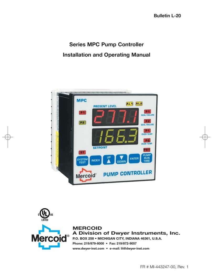
Mercoid
Mercoid Series MPC User manual
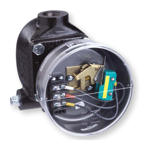
Mercoid
Mercoid 123 Series Installation and operating instructions
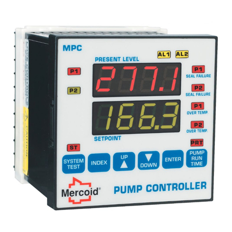
Mercoid
Mercoid Series MPC Installation and operating instructions
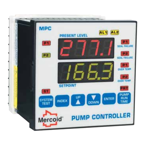
Mercoid
Mercoid Series MPC User manual
Mercoid
Mercoid MPCJR Series Installation and operating instructions
