DOLD SAFEMASTER BH 5902/01MF2 User manual

1BH 5902/01MF2 / 151123 / 613
Betriebsanleitung DEUTSCH
0262834
Vor der Installation, dem Betrieb oder der Wartung des Geräts muss diese
Anleitung gelesen und verstanden werden.
GEFAHR
VORSICHT
Gefährliche Spannung.
Lebensgefahr oder schwere Verletzungsgefahr.
Vor Beginn der Arbeiten Anlage und Gerät spannungsfrei
schalten.
Eine sichere Gerätefunktion ist nur mit zertifizierten Komponenten
gewährleistet!
Hinweise
Die hier beschriebenen Produkte wurden entwickelt, um als Teil einer
Gesamtanlage oder Maschine sicherheitsgerichtete Funktionen zu
übernehmen. Ein komplettes sicherheitsgerichtetes System enthält in
der Regel Sensoren, Auswerteeinheiten, Meldegeräte und Konzepte für
sichere Abschaltungen. Es liegt im Verantwortungsbereich des Herstellers
einer Anlage oder Maschine die korrekte Gesamtfunktion sicherzustellen.
DOLD ist nicht in der Lage, alle Eigenschaften einer Gesamtanlage oder
Maschine, die nicht durch DOLD konzipiert wurde, zu garantieren. Das
Gesamtkonzept der Steuerung, in die das Gerät eingebunden ist, ist vom
Benutzer zu validieren. DOLD übernimmt auch keine Haftung für Empfeh-
lungen, die durch die nachfolgende Beschreibung gegeben bzw. impliziert
werden. Aufgrund der nachfolgenden Beschreibung können keine neuen,
überdieallgemeinenDOLD-Lieferbedingungenhinausgehenden,Garantie-,
Gewährleistungs- oder Haftungsansprüche abgeleitet werden.
Sicherheitsbestimmungen
- Das Gerät darf nur von sachkundigen Personen installiert und in Betrieb
genommen werden, die mit dieser Betriebsanleitung und den geltenden
Vorschriften über Arbeitssicherheit und Unfallverhütung vertraut sind.
- Beachten Sie die VDE- sowie die örtlichen Vorschriften, insbesondere
hinsichtlich Schutzmaßnahmen.
- DerBerührungsschutzderangeschlossenenElementeunddieIsolationder
Zuleitungen sind für die höchste am Gerät anliegende Spannung auszulegen.
- Durch Öffnen des Gehäuses oder eigenmächtige Umbauten erlischt
jegliche Gewährleistung.
- Montieren Sie das Gerät in einen Schaltschrank mit Schutzart IP 54 oder
besser; Staub und Feuchtigkeit können sonst zu Beeinträchtigungen
der Funktionen führen.
- Sorgen Sie an allen Ausgangskontakten bei kapazitiven und induktiven
Lasten für eine ausreichende Schutzbeschaltung.
- Die Sicherheitsfunktion muss mindestens einmal im Monat ausgelöst werden.
Das BH 5902/01MF2 dient dem sicherheitsgerichteten Unterbrechen eines
Sicherheitsstromkreises.Es kann im Schutz-, Muting- und Taktbetrieb zum
Schutz von Personen und Maschinen in Anwendungen mit Lichtgittern
verwendet werden.
Bei bestimmungsgemäßer Verwendung und Beachtung dieser Anleitung
sind keine Restrisiken bekannt. Bei Nichtbeachtung kann es zu Personen-
und Sachschäden kommen.
Bestimmungsgemäße Verwendung
Praxishinweise
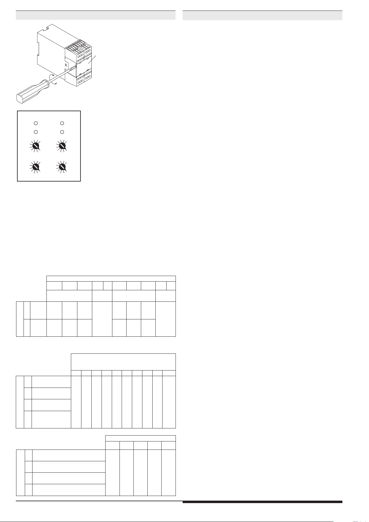
•Vor dem Abnehmen der Platte an der Frontseite muss für einen Poten-
tialausgleich gesorgt werden.
•Bei Mutingbetrieb muss die Mutingleuchte den Angaben der
EN 61496-1 Abschnitt A7.4 entsprechen.
•Wird eine BWS nicht benötigt, müssen jeweils 2 Brücken für jede nicht
benötigte BWS gemäß Bild 9 an die Anschlussklemmen S-1/S-2 und
S-4/S-3 gesetzt werden.
Sicherheitshinweise
ACHTUNG!
•Beim BH 5902.22 darf der Öffnerkontakt 31 - 32 nur als Meldesignal
verwendet werden.
•Nicht geeignet für Anlagen bei denen die BWS hintertretbar sein soll
•Einstellungen am Gerät sind vom Fachpersonal im spannungslosen
Zustand durchzuführen.
Anschlussklemmen
Klemmenbezeichnung Signalbeschreibung
A1+ + / L
A2 - / N
S12, S14, S22, S24, S32, S34,
S42, S44, M1, M2 Steuereingänge
S21, S23, S31, S33, S33, S41, S43 Steuerausgänge
13, 14, 23, 24, 33, 34 Schließer zwangsgeführt für
Freigabekreis
31,32 Öffner zwangsgeführt für
Meldesignal
48, 58 Halbleiter-Meldeausgang
X44 freie Verbindungsklemme,
potentialfrei
Geräteeigenschaften
•entspricht
- Performance Level (PL) e und Kategorie 4 nach EN ISO 13849-1: 2008
- SIL-Anspruchsgrenze (SIL CL) 3 nach IEC/EN 62061
- Safety Integrity Level (SIL) 3 nach IEC/EN 61508
- Kategorie 4 nach EN 954-1
•zum Anschluss von max.
- 3 BWS (berührungslos wirkende Schutzeinrichtung) 2-kanalig oder
- 2 BWS 2-kanalig und 2 Muting-Sensoren 1-kanalig oder
- 1 BWS 2-kanalig und 4 Muting-Sensoren 1-kanalig oder
- 2 BWS 2-kanalig und Schlüsselschalter für Taktumschaltung
- zusätzlich: Start-Taster und Maschinenkontakt mit Leitungs-
schlusserkennung
•Drahtbrucherkennung des BWS-Anschlusses
•Ausgänge:
- 3 Schließer oder 2 Schließer und 1 Öffner
- 2 Halbleiterausgänge, kurzschlussfest und überlastsicher
•Multifunktionsgerät, umschaltbar über Drehschalter für die
Betriebsarten:
- Schutzbetrieb, z. B. Lichtvorhänge
- Schutzbetrieb mit Muting, z. B. Förderbänder
* Einstellung unterschiedlicher Signalfolgen der Muting-Sensoren
* Einstellbarkeit der max. zulässigen Mutingzeit
* Override-Funktion über Starttaster
- Taktbetrieb, z. B: Pressen
* wahlweise 1, 2 oder 3 Takte
* Taktzahl-Einstellung wahlweise mit Schlüsselschalter
•geeignet für den Anschluss von BWS Typ 4 oder von getesteten
BWS Typ 2 gemäß IEC/EN 61 496-1, Querschlusserkennung in BWS
•mit Unter- und Überspannungserkennung und -signalisierung
•Reaktionszeiten: max. 30 ms
•LED-Anzeigen für RUN-Betrieb, Kanal 1/2
SAFEMASTER
Lichtgittermodul mit umschaltbaren Funktionen
BH 5902/01MF2 Originalbetriebsanleitung
Alle Angaben in dieser Liste entsprechen dem technischen Stand zum Zeitpunkt der Ausgabe.
Technische Verbesserungen und Änderungen behalten wir uns jederzeit vor.

2BH 5902/01MF2 / 151123 / 613
Geräteeinstellung
Platte
M2347_a
Einstellbeispiel:
einzustellende Funktion:
SchutzbetriebmitMuting, Hand-
Start, 4 Mutingsensoren),
max. 30 s Mutingzeit
Einstellung an den oberen bei-
den Drehschaltern: jeweils "5"
(für beide Prozessoren)
Einstellung an den unteren bei-
den Drehschaltern: jeweils "2"
(für beide Prozessoren)
Die Funktionseinstellung des BH 5902 erfolgt über 4 Drehschalter (Poti)
hinter der oben abgebildeten Platte. Die Drehschalter "links" dienen zur
Einstellung von Prozessor 1 (ch1) und die Drehschalter "rechts" zur Ein-
stellung von Prozessor 2 (ch2). Für beide Prozessoren muss die gleiche
Funktion eingestellt werden. An den beiden oberen Drehschaltern (1)
erfolgt die Einstellung der Hauptfunktion. An den beiden unteren (10)
die Einstellung der max. zulässigen Mutingzeit (bei Schutzbetrieb) bzw.
Taktzahl (bei Taktbetrieb).
DieFunktionseinstellungbeziehtsichnuraufdieBWS1.In den Betriebsarten
mit Muting und in den Takt-Betriebsarten werden die BWS 2 und 3 immer
in der Betriebsart Schutzbetrieb mit Hand-Start betrieben.
Schutzbetrieb ohne Muting
03
69
03
69
03
69
03
69
ch1 ch2
10
1
M8015
Ansicht innen
Schutzbetrieb mit Muting
Poti 10:
a = max. Mutingzeit
b = max. Synchronisationszeit
012345678 9
Pot.1
2BWS1 Auto-Start,
Muting 2 Signale
a: 10 s / b: 3 s
a: 20 s / b: 3 s
a: 30 s / b: 3 s
a: 1 min / b: 6 s
a: 5 min / b: 30 s
a: 15 min / b: 90 s
a: 30 min / b: 3 min
a: 1 h / b: 3 min
a: 8 h / b: 3 min
keine Muting
Zeitüberwachungen
3
BWS1 Hand-Start,
Muting 2 Signale
4BWS1 Auto-Start,
Muting 4 Signale
5
BWS1 Hand-
Start
,
Muting 4 Signale
Taktbetrieb Poti 10: Anzahl Takte
0 1 2 3 4 - 9
Poti 1
6Kontakt-Abfrageart 1,
Start-Sequenz: Takte und Start
umschaltbar über
Schlüsselschalter
1 Takt
2 Takte
3 Takte
nicht zugelassen
(Fehler 5)
7Kontakt-Abfragear 2,
IStart-Sequenz: Takte und Start
8Kontakt-Abfrageart 1
Start-Sequenz: Start und Takte
9Kontakt-Abfrageart 2
Start-Sequenz: Start und Takte
Poti 10: Startart und Kontaktverstärkung
0 1 2 3 4 5 6 7 8 9
ohne
Kontaktverstärkung
mit
Kontaktverstärkung
Pot.1
0
BWS1
BWS2
BWS3
Auto
Hand
Hand
Auto
Auto
Hand
Auto
Auto
Auto
nicht
zuge-
lassen
(Fehler
5)
Auto
Hand
Hand
Auto
Auto
Hand
Auto
Auto
Auto
nicht
zuge-
lassen
(Fehler
5)
1
BWS1
BWS2
BWS3
Hand
Hand
Hand
Hand
Auto
Hand
Hand
Auto
Auto
Hand
Hand
Hand
Hand
Auto
Hand
Hand
Auto
Auto
Geräteanzeigen
untere grüne LEDs
K1, K2: - leuchten bei bestromten Relais K1 und K2
obere gelbe LED
run 1: - leuchtet mit Dauerlicht bei bestromtem
Relais K1 und K2
- blinkt gleichmäßig mit ca. 1 Hz, wenn im
normalen fehlerfreien Ablauf (z. B. nach Ein-
schalten der Spannung) auf die Betätigung
des Starttasters gewartet wird
- blinkt schnell mit ca. 3 Hz, wenn bei Muting
beim Betätigen des Starttasters alle Bedingungen
für ein Override erfüllt sind
- blinkt schnell mit ca. 3 Hz, wenn beim Takt-
betrieb auf die geforderten Eingriffe in die
BWS gewartet wird
- blinkt mit Fehlercode, um normale Funktions-
zustände anzuzeigen, die ein Bestromen der
Sicherheitsrelais verhindert haben (z.B. nach
einem unerlaubten Eingriff) bis der Starttaster
betätigt wird
- blinkt mit Fehlercode, um ungewöhnliche
Betriebsfehler anzuzeigen (z. B. Unterspannung)
Halbleiterausgang 48: - Aus bei ungewöhnlichen Betriebsfehlern
- normalerweiser Aus beim bestromten
Relais K1 und K2
- An mit Dauerlicht bei aktivem Muting
- Blinksignale wie LED run 1
(außer bei ungewöhnlichen Betriebsfehlern)
obere gelbe LED run 2: - leuchtet mit Dauerlicht bei fehlerfreier Funktion
- blinkt mit Fehlercode, um ungewöhnliche
Betriebsfehler anzuzeigen (z. B. Unterspannung)
Halbleiterausgang 58: - Aus bei ungewöhnlichen Betriebsfehlern
- Aus bei bestromten Relais K1 und K2
- blinkt regelmäßig, solange ein normaler
Funktionszustand ansteht, der ein Bestromen
der Sicherheitsrelais verhindert (z. B. ein uner-
laubter Eingriff in eine BWS)
- An mit Dauerlicht, wenn auf die Betätigung des
Starttasters gewartet wird

3BH 5902/01MF2 / 151123 / 613
Betriebsart: Schutzbetrieb (Anwendungsbeispiel M7961)
z. B. Lichtvorhänge zur Absicherung von Gefahrenbereichen
•bis zu 3 BWS anschließbar
•wahlweise Auto- oder Hand-Start für jede BWS einzeln einstellbar
•mit oder ohne Kontaktverstärkung einstellbar
Mögliche Einstellungen:
M7942
Poti 10: Startart und Kontaktverstärkung
0 1 2 3 4 5 6 7 8 9
ohne
Kontaktverstärkung
mit
Kontaktverstärkung
Pot.1
0
BWS1
BWS2
BWS3
Auto
Hand
Hand
Auto
Auto
Hand
Auto
Auto
Auto
nicht
zuge-
lassen
(Fehler
5)
Auto
Hand
Hand
Auto
Auto
Hand
Auto
Auto
Auto
nicht
zuge-
lassen
(Fehler
5)
1
BWS1
BWS2
BWS3
Hand
Hand
Hand
Hand
Auto
Hand
Hand
Auto
Auto
Hand
Hand
Hand
Hand
Auto
Hand
Hand
Auto
Auto
•Automatischer Start
Beim automatischen Start erfolgt eine sofortige Aktivierung der Maschi-
nenfreigabekontakte K1 und K2, sobald die mit Autostart programmierte
BWS nach einer Lichtwegunterbrechung wieder freigegeben wird.
Voraussetzung ist, dass die mit Handstart programmierten BWS nicht
unterbrochen sind.
•Hand-Start
Bei dieser Betriebsart erfolgt die Aktivierung der Maschinenfreigabekon-
takte K1 und K2 erst, wenn die mit Handstart programmierte BWS nach
einer Lichtwegunterbrechung wieder freigegeben und die Start-Taste
betätigt wird ®.
Die Start-Taste muss bei zwei Zuständen betätigt werden:
- nach Wiederkehr der Vorsorgungsspannung
(wenn mindestens 1 BWS mit Handstart programmiert ist)
- wenn eine BWS mit Handstart unterbrochen war ®
Funktionsdiagramm
1
2
3
M7967_
a
Versorgungsspannung
(A1/A2)
Starttaste (S43/S44)
BWS1(S12/S14)
mit Autostart
BWS2(S22/S24) und/oder
BWS3(S32/S34)
mit Handstart
K1, K2
(13-14, 23-24, 33-34)
Warten auf Start (58)
Fehleranzeige (48)
Blinkcode
: dunkel : Dauerlicht : Blinkcode : gleichmäßiges Blinken
11

4BH 5902/01MF2 / 151123 / 613
Betriebsart: Schutzbetrieb mit Muting
Maschine
gemutete BWS
MS1MS2
Fördergut Förderband
M7970_a
Mutingleuchte
BWS
BWS, gemutet
Muting-Sensor MS1
Muting-Sensor MS2
Mutingleuchte
Mutingleuchtenkontrolle
t < 50ms
2
t < 50ms
2
t < 30ms
1
t < 30ms
1
t<Mutingdauer (a)
30ms t
t<Synchronzeit (b)
30ms t
t<Synchronzeit (b)
Verwendung von 2 Muting-Sensoren
Verwendung von 4 Muting-Sensoren
BWS
Maschine För dergut Förderband
BWS, gemutet
Muting-Sensor MS1
Muting-Sensor MS3
Muting-Sensor MS2
Muting-Sensor MS4
Mutingleuchte
Mutingleuchtenkontrolle
t < 50ms
t > 30ms
t < 50ms
t < 30ms
t < 30ms
MS3MS4 MS2MS1
M7972_a
Mutingleuchte
gemutete BWS
t<Mutingdauer (a)
30ms t
t<Synchronzeit (b)
30ms t
t<Synchronzeit (b)
Betriebsart: Schutzbetrieb mit Muting
z. B. Förderband
•1 oder 2 BWS
•Muting von BWS1
•2 oder 4 Muting-Sensoren mit verschiedenen Signalfolgen
•BWS1 mit Auto- oder Hand-Start
•BWS2 immer mit Hand-Start
•Override über Starttaster
•Handstart ist bei Spannungseinschalten immer erforderlich
Muting (Überbrückung)
Das Muting dient dem vorübergehenden Unwirksamschalten einer BWS.
Diese Funktion wird verwendet, um Fördergut durch eine BWS ungehindert
transportieren zu können. Die Unterscheidung Fördergut oder Mensch wird
durchzusätzlicheMuting-Sensoren(MS) realisiert,die eine ganz bestimmte
Signalreihenfolge generieren müssen, wenn Fördergut die BWS passiert.
Die Mutingsteuerung startet dann den Mutingzyklus für die Zeit, in der das
Material durch die BWStransportiert wird.Einer Persondarfes nicht möglich
sein, die Mutingsensoren in der gleichen Signalfolge zu aktivieren wie das
Fördergut.Um dies sicher zustellen, können am BH 5902 Betriebsarten mit
2 oder 4 Mutingsignalen eingestellt werden. Damit löst eine Person beim
Zugang in die BWS die Abschaltung der gefahrbringenden Bewegung aus.
DerMutingvorgangwird mittels einer vomGerät überwachtenMutingleuchte
signalisiert. Die maximal zulässige Dauer des Mutingvorgangs kann in 10
Stufen zwischen 10 s und unendlich eingestellt werden. Ist die BWS1 nach
Ablauf der max. zulässigen Mutingzeit noch unterbrochen, z.B. durch ver-
klemmtes Fördergut, öffnen die Maschinen-Freigabekontakte K1, K2 und
die Mutingleuchte sowie die LED run 1 signalisieren FEHLER-4.
Eine Freigabe durch die Starttaste ist nur möglich, wenn die Mutingleuchte
in Ordnung und die zu überbrückende BWS frei ist. Während dem
Mutingzyklus führt ein Fehler in der Reihenfolge der Mutingsignale oder
ein Überschreiten der max. zulässigen Mutingzeit zu FEHLER-4. Dieser
kann nur durch Quittieren über den Starttaster wieder beseitigt werden.
Die Mutingsignalquellen sind so anzubringen, dass durch einen Eingriff
oder Eintritt in die BWS die richtige Signalfolge nicht erzeugt werden kann
(siehe hierzu die Angaben in IEC/EN 61496-1).
Mögliche Einstellungen:
Poti 10:
a = max. Mutingzeit
b = max. Synchronisationszeit
012345678 9
Pot.1
2BWS1 Auto-Start,
Muting 2 Signale
a: 10 s / b: 3 s
a: 20 s / b: 3 s
a: 30 s / b: 3 s
a: 1 min / b: 6 s
a: 5 min / b: 30 s
a: 15 min / b: 90 s
a: 30 min / b: 3 min
a: 1 h / b: 3 min
a: 8 h / b: 3 min
keine Muting
Zeitüberwachungen
3
BWS1 Hand-Start,
Muting 2 Signale
4BWS1 Auto-Start,
Muting 4 Signale
5
BWS1 Hand-
Start
,
Muting 4 Signale
Override
Ist der Überwachungsbereich bei abgefallenen Sicherheitsrelais durch ein
Fördergut blockiert, wird dies beim Betätigen der Starttaste durch ein
schnelles Blinken (ca. 3 Hz) der Mutingleuchte signalisiert. Der Bediener
kann die Sicherheitsrelais durch ein längeres Betätigen des
Starttasters nach 3 Sekunden für maximal 12 Sekunden freigeben, bis
die Mutingsensoren wieder inaktiv werden oder die Starttaste nicht mehr
gedrückt wird.
Beispiel eines Override-Zyklus bei Muting mit 2 Sensoren
gemutete BWS1
Muting-Sensor MS1
Muting-Sensor MS2
Mutingleuchte
Sicherheitsrelais K1/K2
Starttaster
ungemutete BWS2
: Dauerlicht : Blinkcode : schnelles Blinken (3Hz)
Fehlercode
M9476
12
t=3S override
t<12 S

5BH 5902/01MF2 / 151123 / 613
Betriebsart:Taktbetrieb
Startsequenz
Um die Maschine bei Taktbetrieb nach dem Einschalten frei zu geben,
können zwei mögliche Startsequenzen gewählt werden:
1.) Es müssen zuerst die geforderten Eingriffe getätigt und dann die
Start-Taste gedrückt werden.
2.) Zuerst ist die Start-Taste zu betätigen. Danach müssen die ge-
forderten Eingriffe erfolgen.
Die Aufforderung, die Eingriffe zu tätigen, (z.B.2Takte gemäß untenstehen-
den Diagrammen) wird durch Blinken der Leuchte (Klemme 48) angezeigt.
Die Aufforderung, die Start-Taste zu betätigen, erfolgt durch Dauerlicht der
Leuchtean Klemme 58.Nach korrektem Ablaufder Startsequenzerlöschen
die Leuchten und die Maschinen-Freigabekontakte K1, K2 schließen.
M7976_a
Versorgungsspannung
(A1/A2)
Starttaste (S43/S44)
BWS1(S12/S14)
BWS2(S22/S24) und/oder
BWS3(S32/S34)
K1, K2
(13-14, 23-24, 33-34)
Warten auf Eingriff (48)
Warten auf Start (58)
: hell
: blinken 1Hz
: dunkel : blinken 3Hz
Start-Sequenz: 2 Takte und Start-Taste
M7977_a
Versorgungsspannung
(A1/A2)
Starttaste (S43/S44)
BWS1(S12/S14)
BWS2(S22/S24) und/oder
BWS3(S32/S34)
K1, K2
(13-14, 23-24, 33-34)
Warten auf Eingriff (48)
Warten auf Start (58)
: hell
: blinken 1Hz
: dunkel : blinken 3Hz
Start-Sequenz: Start-Taste und 2 Takte
Eine korrekt abgelaufene Startsequenz ist Bedingung für den fol-
genden Normalablauf. Bei diesem wird der Hub der Maschine dem
Lichtgittermodul durch das Öffnen und Schließen eines Maschinen-
kontaktes mitgeteilt. Die Ausgangskontakte des Lichtgittermoduls
werden mit dem Öffnen des Maschinenkontaktes inaktiv. Danach
muss der Bediener bewusst die geforderte Anzahl von Eingriffen
(Takten) in die BWS tätigen, um die Maschine automatisch wieder in Gang
zu setzen. Alle geforderten Takte müssen innerhalb von 30 s erfolgen.
Die Aufforderung, die Eingriffe zu tätigen, wird durch Blinken (ca.3 Hz) der
Leuchte (Klemme 48) angezeigt. Wenn alle geforderten Eingriffe erfolgt
sind, erlischt die Leuchte und die Maschinen-Freigabekontakte K1, K2
schließen.
z. B. Pressen mit manuellem Eingriff und automatischem Start
•max. 3 BWS
•BWS2 und BWS3 immer mit Handstart
einstellbare Funktionen:
•1, 2 oder 3 Takte
•Taktzahl über Poti 1 oder über Schlüsselschalter umschaltbar
•2 verschiedene Startsequenzen
•2 Abfragearten des Maschinenkontaktes
M7955
DerTaktbetriebermöglichteinenautomatischenWiederanlaufeiner Maschi-
ne (Presse) nach einer definierten Anzahl von Eingriffen in das Schutzfeld
der ersten BWS. Diese Betriebsart besteht aus einer Startsequenz und
dem Normalablauf.
Mögliche Einstellungen:
Taktbetrieb Poti 10: Anzahl Takte
0 1 2 3 4 - 9
Poti 1
6Kontakt-Abfrageart 1,
Start-Sequenz: Takte und Start
umschaltbar über
Schlüsselschalter
1 Takt
2 Takte
3 Takte
nicht zugelassen
(Fehler 5)
7Kontakt-Abfragear 2,
Start-Sequenz: Takte und Start
8Kontakt-Abfrageart 1
Start-Sequenz: Start und Takte
9Kontakt-Abfrageart 2
Start-Sequenz: Start und Takte

6BH 5902/01MF2 / 151123 / 613
Betriebsart:Taktbetrieb Betriebsart:Taktbetrieb mit Schlüsselschalter
Anwendung: Pressen mit langsamer Hubgeschwindigkeit
M7979_c
BWS1(S12/S14)
Maschinenkontakt
(S41/S42)
K1, K2
(13-14, 23-24, 33-34)
Warten auf Eingriff (48)
Warten auf Start (58)
: hell: dunkel : blinken 3Hz
M7980_b
Starttaste (S43/S44)
BWS1(S12/S14),BWS2
(S22/S24) o. BWS3(S32/S34)
Maschinenkontakt
(S41/S42)
K1, K2
(13-14, 23-24, 33-34)
Warten auf Eingriff (48)
Warten auf Start (58)
: hell
: blinken 1Hz : Fehlercode
: dunkel
Anwendung: Pressen mit durchschnittlicher bis schneller Hub-
geschwindigkeit
M7978_b
BWS1(S12/S14)
Maschinenkontakt
(S41/S42)
K1, K2
(13-14, 23-24, 33-34)
Warten auf Eingriff (48)
Warten auf Start (58)
: hell: dunkel : blinken 3Hz
Maschinenkontakt
An das Gerät muss über die Klemmen S41 - S42 ein Maschinenkontakt
angeschlossen werden. Er öffnet und schließt in Abhängigkeit des Hubs
der Presse.
Abfragearten des Maschinenkontaktes
Es sind zwei Abfragearten des Maschinenkontaktes wählbar:
Abfrageart 1
Bei dieser Abfrageart dürfen die Eingriffe in die BWS erst erfolgen, wenn der
Maschinenkontaktgeöffnet und wieder geschlossenwurde.Eine Ausnahme
ist, wenn der Eingriff bei geöffnetem Kontakt erfolgt und noch andauert,
wenn der Kontakt wieder geschlossen ist.
Unerlaubter Eingriff in BWS
Unerlaubte Eingriffe in die BWS führen zum Abschalten der Maschinen-
Freigabekontakte K1, K2. Bei unerlaubten Eingriffen blinkt die Leuchte
(Klemme 58) regelmäßig.Die Leuchte an Klemme 48 blinkt mit dem Fehler-
code 1. Nach Beendigung des Eingriffs geht die Leuchte an Klemme 58 in
Dauerlicht über und signalisiert, dass der Maschinenstart durch Betätigung
der Start-Taste erfolgen kann.
z. B. Pressen mit wechselnder Taktzahl
• Umschaltmöglichkeit mittels Schlüsselschalter:
-1, 2 oder 3 Takte
Umschalterkennung
Die Umschaltung wird nur bei Maschinenstillstand (K1, K2 offen)
erkannt.
Die Erkennung der neuen Schlüsselschalterstellung wird durch die Anzeige
des Fehlercodes 3 an der Leuchte der Klemme 48 signalisiert. Mittels
Freigabe durch Start-Tasten-Betätigung erfolgt zuerst ein Neu-Start des
Gerätes. Die bereits eingestellte Start-Sequenz mit der geänderten Taktzahl
muss nach dieser ersten Start-Tasten-Betätigung komplett (Takte und Start-
Taste bzw. Start-Taste und Takte) durchlaufen werden, um die Maschine
mit der neuen Taktzahl frei zu geben.
Abfrageart 2
Bei dieser Abfrageart werden die Eingriffe bereits bei offenem Maschinen-
kontakt erkannt. Die Maschine wird aber erst wieder freigegeben, wenn
sowohl alle Eingriffe getätigt sind, als auch der Maschinenkontakt wieder
geschlossen ist.

7BH 5902/01MF2 / 151123 / 613
Technische Daten
Eingang
Nennspannung UN:DC 24 V
Spannungsbereich:
bei max. 5 % Restwelligkeit: 0,85 ... 1,15 UN
Nennverbrauch: max. 170 mA
(Halbleiterausgänge unbelastet)
Steuerspannung über
S21, S23, S31, S33, S41, S43,
48, 58: DC 23 V bei UN
Steuerstrom über
S12, S14, S22, S24,
S32, S34, S42, S44: je 4,5 mA bei UN
Mindestspannung an
Klemmen S12, S14, S22,
S24, S32, S34 S42, S44: DC 16 V
Absicherung des Gerätes: Intern mit PTC
Mindeststrom an M1, M2: 25 mA bei eingeschalteter Lampe
Ausgang
Kontaktbestückung
BH 5902.03: 3 Schließer
BH 5902.22: 2 Schließer, 1 Öffner
Der Öffner darf nur als Meldekontakt
verwendet werden !
Kontaktart: Relais, zwangsgeführt
Einschaltzeit typ. bei UN:
Handstart: max. 50 ms
Automatischer Anlauf: max. 1,5 s
Automatischer Wiederanlauf: max. 55 ms
Abschaltzeit (Reaktionszeit): max. 30 ms
(max. 50 ms, wenn Fehler an BWS
und nur 1 Eingangskanal der BWS
abschaltet)
Ausgangsnennspannung: max. AC 250 V
DC: siehe Lichtbogengrenzkurve*)
*) siehe Datenblatt BH 5902/01MF2 unter www.dold.com
Schalten von Kleinlasten: ≥100 mV
Thermischer Strom Ith:5 A
Schaltvermögen
nach AC 15
Schließer: 3 A / AC 230 V IEC/EN 60 947-5-1
Öffner: 2 A / AC 230 V IEC/EN 60 947-5-1
nach DC 13 bei 0,1 Hz: 8 A / DC 24 V IEC/EN 60 947-5-1
Elektrische Lebensdauer
nach AC 15 bei 2 A, AC 230 V: 105Schaltspiele IEC/EN 60 947-5-1
Zulässige Schalthäufigkeit: max. 1 200 Schaltspiele / h
Kurzschlussfestigkeit
max. Schmelzsicherung: 6 A gL IEC/EN 60 947-5-1
Sicherungsautomat: C 8 A
Mechanische Lebensdauer: 10 x 106Schaltspiele
Halbleiterausgänge
Ausgang (Klemme 48 und 58): Transistorausgänge, plus-schaltend
Ausgangsnennspannung: DC 24 V, max. 100 mA Dauerstrom,
max. 400 mA für 0,5 s interner Kurz-
schluss-, Übertemperatur und Überlast-
schutz
Allgemeine Daten
Nennbetriebsart: Dauerbetrieb
Temperaturbereich:
Betrieb: ±0 ... + 50 °C
Lagerung : - 25 ... + 85 °C
Betriebshöhe: < 2.000 m
Luft- und Kriechstrecken
Bemessungsstoßspannung /
Verschmutzungsgrad: 4 kV / 2 (Basisisolierung) IEC 60 664-1
EMV
Statische Entladung (ESD): 8 kV (Luftentladung) IEC/EN 61 000-4-2
(entsprechend Prüfschärfegrad 3)
HF-Einstrahlung: 10 V / m IEC/EN 61 000-4-3
Schnelle Transienten:
auf Versorgungsleitung A1-A2: 2 kV IEC/EN 61 000-4-4
auf Signal und Steuerleitungen: 2 kV IEC/EN 61 000-4-4
Technische Daten
Stoßspannung (Surge)
zwischen
Versorgungsleitungen: 1 kV IEC/EN 61 000-4-5
zwischen Leitung und Erde: 2 kV IEC/EN 61 000-4-5
HF-leitungsgeführt: 10 V IEC/EN 61 000-4-6
Funkentstörung: Grenzwert Klasse B EN 55 011
Schutzart: nach IEC/EN 61 496-1 muss das
Gerät in ein Steuergehäuse mit
Schutzklasse 54 untergebracht werden
Gehäuse: IP 40 IEC/EN 60 529
Klemmen: IP 20 IEC/EN 60 529
Gehäuse: Thermoplast mit V0-Verhalten
nach UL Subject 94
Rüttelfestigkeit: nach IEC/EN 61 496-1
Amplitude 0,35 mm
Frequenz 10 ... 55 Hz, IEC/EN 60 068-2-6
Schockfestigkeit:
Beschleunigung: 10 g
Impulsdauer: 16 ms
Anzahl der Schocks: 1000 je Achse auf drei Achsen
Klimafestigkeit: 0 / 050 / 04 IEC/EN 60 068-1
Klemmenbezeichnung: EN 50 005
Leiterbefestigung: unverlierbare Plus-Minus-Klemmen-
schrauben M3,5 Kastenklemmen mit
selbstabhebendem Drahtschutz
Schnellbefestigung: Hutschiene IEC/EN 60 715
Nettogewicht: 320 g
UL-Daten
Die Sicherheitsfunktionen des Gerätes wurden nicht durch die UL
untersucht. Die Zulassung bezieht sich auf die Forderungen des
Standards UL508,“general use applications“
Nennspannung UN: DC 24 V
Umgebungstemperatur: 0 … +50°C
Schaltvermögen:
Umgebungstemperatur 50°C: Pilot duty B300
5A 250Vac G.P.
5A 24Vdc
Halbleiterausgänge: 24Vdc, 100 mA
Leiteranschluss: nur für 60°C / 75°C Kupferleiter
AWG 20 - 12 Sol Torque 0.8 Nm
AWG 20 - 14 Sol Torque 0.8 Nm
nfo
Fehlende technische Daten, die hier nicht explizit angegeben
sind, sind aus den allgemein gültigen technischen Daten zu
entnehmen.

8BH 5902/01MF2 / 151123 / 613
Vorgehen bei Störungen
Bei Erkennen eines Fehlers fallen immer die Relais K1/K2 ab.
Die unterschiedlichen Fehler werden durch verschiedene Blinkfolgen an
den LEDs run 1 und run 2 angezeigt.
Die Unterscheidung der Fehler erfolgt in 2 Gruppen.
Fehlergruppe 1:
Systemfehler
Nach Erkennen eines solchen Fehlers verriegelt sich das Modul und zeigt
nur noch den Fehlercode an. Das Modul kann nur durch Aus- und Wieder-
einschalten des Moduls zurückgesetzt werden. Diese Fehler werden nur
an den LEDs run 1 und/oder run 2 angezeigt. Es können zur gleichen Zeit
verschiedeneFehlercodesanbeidenLEDsangezeigtwerden.DieAusgänge
48 und 58 sind in diesem Zustand immer dauernd ausgeschaltet.
Fehlergruppe 2:
Funktionsfehler
Diese Fehler werden immer an der LED run1 und am Ausgang 48 ange-
zeigt, während die LED run 2 im Dauerlicht bleibt. Die Relais K1/K2 sind
in diesem Zustand inaktiv. Das Modul ist aber noch voll funktionsfähig und
die Relais können wieder aktiviert werden, wenn der Fehler behoben ist,
und die Starttaste betätigt wird.
Vorgehen bei Störungen
Systemfehler: (nur an LEDs run 1 und/oder run 2 angezeigt)
Nr.*)Beschreibung Maßnahmen und Hinweise
0interner Gerätefehler (beide
LEDs sind konstant aus)
Wenn beide LEDs aus bleiben,
ist das Gerät defekt und muss zur
Reparatur
5 Einstellfehler
1) Die Drehschalterstellungen
der beiden Kanäle stimmen
nicht überein.
2) Die gewählte Einstellung ist
nicht zulässig.
6 Unterspannungserkennung
Linke LED blinkt.
Die Versorgungsspannung ist
unter die zulässige Spannung
gesunken (< ca. 0,85 UN). Nach
jedem Anzeigenzyklus des Feh-
lercodes wird die Spannung neu
gemessen. Ist sie wieder im zu-
lässigen Bereich, wird ein Reset
(wie beim Einschalten der
Versor-
gungsspannung) des Moduls
durchgeführt.
6 Überspannungserkennung
Rechte LED blinkt:
Die Versorgungsspannung ist
zu hoch
(> ca. 1,15 UN+ 5 % Restwelligkeit).
7 Eingangsfehler
1) Es ist ein Kurzschluss an
den Eingängen der Start-
Taste oder des Maschinen-
kontaktes (Schutzbetrieb)
aufgetreten
2) Die zwei Signale einer CDS
stimmen nicht überein
(Kurzschluss, Leitungsbruch
oder defekte CDS)
8Fehler an den Maschinen-
freigaberelais K1, K2
Schaltung und Schaltströme
überprüfen. Das Gerät
muss zur Reparatur.
9
10
11
interne Gerätefehler
Versuchen Sie den Ablauf fest-
zustellen, der zu dieser Fehler-
meldung führt und teilen Sie
diesen Ablauf dem Hersteller
oder Verkäufer des Gerätes mit.
12
13
interne Gerätefehler Das Gerät muss zur Reparatur.
*) Nr.: Anzahl der aufeinanderfolgenden Blinkimpulse
Funktionsfehler: Anzeige an run 1 und Ausgang 48
Nr.*)Beschreibung Maßnahmen und Hinweise
1 BWS Fehler
1)
Eine BWS wurde unterbrochen.
2) anstelle unbenutzter BWS
müssen Brücken vorhanden
sein:
BWS 2: S21-S22, S23-S24
BWS 3: S31-S32, S33-S34
2 Fehler am Starttaster
1) Der Starttaster darf nicht
beim Einschalten des Moduls
betätigt sein.
2) Der Starttaster darf nicht län-
ger als 3 s betätigt sein.
3Reiner Schutzbetrieb:
FSD-Fehler
1) Es ist eine Betriebsart mit
Kontaktverstärkung eingestellt
und der überwachte Kontakt,
der
an S41 - S42 angeschlossen
wer
den muss, ist vor dem
Aktivieren der Relais K1, K2
nicht geschlossen.
3Taktbetrieb
Kontaktfehler
1) Der Maschinenkontakt ist
im Ruhezustand des Sicher-
heitsmoduls (Warten auf
die Startbedingung) nicht
angeschlossen.
2) Bei Kontaktart 1 war der
Maschinenkontakt am Ende
des geforderten 1. Eingriffs
in die BWS noch offen.
4Muting-Fehler
(Blockierung)
1) Die eingestellte max. Muting-
dauer wurde überschritten
(Mutinglampe an).
4Muting-Fehler
(Lampe)
2) Die Mutinglampe ist nicht
zwischen der Klemme 48 und
den Klemmen M1 und M2 an-
geschlossen.
3) Die erforderliche Brücke an
den Klemmen S41 und S42
ist nicht angeschlossen.
4) Die Mutinglampe ist defekt.
5) Die Messschaltung für die
Mutinglampe ist defekt.
Das Gerät muss zur Reparatur.
5Taktbetrieb
(Schlüsselfehler)
1) Beide Kontakte des
Schlüsselschalters für die
Einstellung der Taktzahl sind
offen.
*) Nr.: Anzahl der aufeinanderfolgenden Blinkimpulse
Zustandsanzeigen
run 1 und Ausgang 48 blinken schnell mit ca. 3 Hz
Muting-Betrieb:
Override möglich
Mindestens ein Mutingsensor ist
aktiv, BWS 1 ist unterbrochen und
der Starttaster wird betätigt. Nach
3 s ununterbrochener Betätigung
des Starttasters wird das Override
für max. 12 s eingeleitet.
Taktbetrieb:
Warten auf Eingriffe
Es wird auf die vorgegebene An-
zahl der Eingriffe in die BWS ge-
wartet, um die Sicherheitsrelais
wieder aktivieren zu können.
Wartung und Instandsetzung
- Das Gerät enthält keine Teile, die einer Wartung bedürfen.
- Bei vorliegenden Fehlern das Gerät nicht öffnen, sondern an den
Hersteller zur Reparatur schicken.

9BH 5902/01MF2 / 151123 / 613
Operating instructions ENGLISH
SAFEMASTER
Light curtain controller with selectable
operating modes BH 5902/01MF2
0262834
The BH 5902/01MF2 interrupts a safety circuit in a safe way. In applications
with light curtains it can be operated in protection, muting and stepping
mode to protect people and machinery.
When used in accordance with its intended purpose and following these
operating instructions, this device presents no known residual risks. Non-
observance may lead to personal injuries and damages to property.
Designated use
Practical notes
•Before removing the front plate the person must be discharged to
ground.
•The muting lamp must be conform to IEC/EN 61 496-1 section A7.4
•If an input is not used, 2 wire links have to be made according to picture
9 on the terminals S-1/S-2 and S-4/S-3.
Safety notes
ATTENTION!
•On BH 5902.22 the NC contact 31-32 must only be used as monitoring
contact.
•Not suitable for machines where the area behind the light curtain is
accessable
•Settings have to be carried out by educated personnel with disconnected
Connection Terminals
Terminal designation Signal designation
A1+ + / L
A2 - / N
S12, S14, S22, S24, S32, S34,
S42, S44, M1, M2 Inputs
S21, S23, S31, S33, S33, S41, S43 Outputs
13, 14, 23, 24, 33, 34 Forcibly guided NO contacts for
release circuit
31,32 Forcibly guided NC contacts for
release circuit
48, 58 Semiconductor monitoring output
X44 Free junction terminal,
volt free
Main features
•According to
- Performance Level (PL) e and category 4 to EN ISO 13849-1: 2008
- SIL Claimed Level (SIL CL) 3 to IEC/EN 62061
- Safety Integrity Level (SIL) 3 to IEC/EN 61508
- Category 4 to EN 954-1
•To connect max.:
- 3 light curtains 2-channel or
- 2 light curtains 2-channel and 2 muting sensors 1-channel or
- 1 light curtain 2-channel and 4 muting sensors 1-channel or
- 2 light curtains 2-channel and key switch for stepping operation
- additionally: Start button and machine contact with line fault detection
•Broken wire detection on light curtain input
•Outputs:
- 3 NO or 2 NO and 1 NC
- 2 Semiconductor outputs, protected against short circuit and overload
•Multifunction device, different functions selectable by rotational
switches:
- protective operation e.g. light curtains
- protective operation with muting, e.g. conveyors
* signal sequence of muting sensors can be selected
* override function via start button
- Stepping operation e.g. on presses
* optionally with key switch
* 1, 2 or 3 steps possible
* setting of number of step possible via selector switch
•Suitable to connect light curtains of type 4 or selftesting light curtains
type 2 according to IEC/EN 61 496-1, crossfault monitoring in the light
curtain
•With under- and overvoltage detection and indication
•Reaction time: max. 30 ms
•LED indication for RUN and Channel 1,2
Before installing, operating or maintaining this device, these instructions
must be carefully read and understood.
DANGER
CAUTION
Dangerous voltage.
Electric shock will result in death or serious injury.
Disconnect all power supplies before servicing equipment.
Safe operation of the device is only guaranteed when using certified
components!
Important Notes
The product hereby described was developed to perform safety functions
as a part of a whole installation or machine. A complete safety system
normally includes sensors, evaluation units, signals and logical modules
for safe disconnections. The manufacturer of the installation or machine
is responsible for ensuring proper functioning of the whole system. DOLD
cannot guarantee all the specifications of an installation or machine that
was not designed by DOLD. The total concept of the control system into
which the device is integrated must be validated by the user. DOLD also
takes over no liability for recommendations which are given or implied in
the following description. The following description implies no modification
of the general DOLD terms of delivery, warranty or liability claims.
Safety Regulations
- This device must be installed and operated by trained staff who are
familiar with these instructions and with the current regulations for safety
at work and accident prevention.
- Pay attention to applicable local regulations, especially regarding safety
measures.
- The shock protection on the connected elements and the cable insulation
must be designed for the highest voltage applied to the device.
- Opening the device or implementing unauthorized changes voids any
warranty
- The unit should be panel mounted in an enclosure rated at IP 54 or
superior. Dust and dampness may lead to malfunction.
- Adequate fuse protection must be provided on all output contacts with
capacitive and inductive loads.
- The safety function must be triggered at least once a month.
Translation
of the original instructions
Alle Angaben in dieser Liste entsprechen dem technischen Stand zum Zeitpunkt der Ausgabe.
Technische Verbesserungen und Änderungen behalten wir uns jederzeit vor.

10 BH 5902/01MF2 / 151123 / 613
Setting
Example:
Required function: Protective
operation with manual start,
with muting, 4 muting sensors,
max. 30 s muting time.
Setting:
Upper switches set to "5" for
both µprocessors
Lower switches set to "2" for
both µprocessors
The function setting of BH 5902 is made by 4 rotational switches behind
the frontplate (see picture). The switches on the left make the setting for
µprocessor 1 (LED run 1) and the switches on the right for µprocessor (LED
run 2). For both processors the same functions must be set. On the upper
switches (1) the main function is adjusted. On the lower switches (10) the
setting of the muting time (Protective operation) or the number of steps
(stepping operation) is adjustable.
On muting or stepping function the light curtains LC 2 and LC 3 are always
in protective operation with manual start.
Protective operation without muting
03
69
03
69
03
69
03
69
ch1 ch2
10
1
M8015
Ansicht innen
Protective operation with muting
Indicators
lower green LEDs
K1, K2: - on, when K1 and K2 are energized
upper yellow LED
run 1: - permanent on, when relay K1 and K2 are energized
- f
lashes with 1 Hz when the unit waits for
the start
signal after fault free operation (power up of the unit)
- flashesfastwithapprox.3Hzwhen the startbutton
is pressed and all conditions for an override are
fulfilled during muting
- flashes fast with approx. 3 Hz when at stepping
operation the unit waits for interruption of the
light curtain
- flasheswithfailurecodetoindicatenormalindication
states that disable the energisation of the output
relays (e.g. after not allowed interruption of the
light curtain) until the start button is pressed
- flashes with failure code to indicate
special failures (e.g. undervoltage)
semiconductor output 48: - off, when unit is on special failure mode
- normally off when relays K1 and K2 are energized
- continuously on, when unit in muting mode
- shows the same failure codes as LED
run 1 (except on special failures)
upper yellow LED run 2: - permanent on, when unit operates
correctly
- flashes with failure code to indicate
special operation failures (e.g.
undervoltage)
semiconductor output 58: - off, when unit is on special failure
mode
- off, when relays K1 and K2 are
energized
- symmetric flashing, when a normal
functional state is active that disables
the energisation of the output relays
(e.g. not allowed interruption of a light
curtain)
- permanent on, when waiting for start
Switch 10: Start mode and feedback input
0 1 2 3 4 5 6 7 8 9
without feedback
input with feedback input
Switch 1
0 LC 1
LC 2
LC 3
Auto
Manu
Manu
Auto
Auto
Manu
Auto
Auto
Auto
not
allowed
(fault 5)
Auto
Manu
Manu
Auto
Auto
Manu
Auto
Auto
Auto
not
allowed
(fault 5)
1 LC 1
LC 2
LC 3
Manu
Manu
Manu
Manu
Auto
Manu
Manu
Auto
Auto
Manu
Manu
Manu
Manu
Auto
Manu
Manu
Auto
Auto
Switch 10:
a = maximum muting time
b = maximum synchronising time
0 1 2 3 4 5 6 7 8 9
Switch 1
2LC S1 Auto,
muting 2 sensors
a: 10 s / b: 3 s
a: 20 s / b: 3 s
a: 30 s / b: 3 s
a: 1 min / b: 6 s
a: 5 min / b: 30 s
a: 15 min / b: 90 s
a: 30 min / b: 3 min
a: 1 h / b: 3 min
a: 8 h / b: 3 min
no muting time monitoring
3LC S1 Manu,
muting 2 sensors
4LC S1 Auto,
muting 4 sensors
5LC S1 Manu,
Muting 4
sensors
Stepping operation Switch 10: Number of steps
0 1 2 3 4 - 9
Switch 1
6Stepping operation, contact type 1,
Start-sequence: stepping and start
selectable by key
switch
1 step
2 step
3 step
not allowed (fault 5)
7Stepping operation, contact type 2,
Start-sequence: stepping and start
8Stepping operation, contact type 1,
Start-sequence: start and stepping
9Stepping operation, contact type 2,
Start-sequence: start and stepping
plate
M2929

11 BH 5902/01MF2 / 151123 / 613
Operation mode: Protective operation (see M7961)
e.g. light curtains to secure dangerous areas
•Connection up to 3 light curtains
•Manual or automatic start possible for each light curtain
•With or without feedback input for external contactors
Possible settings:
M7942
•Automatic start
On automatic start the contacts K1 and K2 are energized when the light
curtain that is set for auto start is free after interruption. It is necessary
that the other light curtains with manual start are not interruped.
•Manual start
On manual start the contacts K1 and K2 are energized when the light
barrier that is set for manual start is free after interruption and the start
button is pressed
The start button must be activated in 2 conditions:
- after return of the supply voltage
(when minimum 1 light curtain is programmed for manual start)
- when 1 light curtain with manual start was interrupted
Switch 10: Start mode and feedback input
0 1 2 3 4 5 6 7 8 9
without feedback
input with feedback input
Switch 1
0 LC 1
LC 2
LC 3
Auto
Manu
Manu
Auto
Auto
Manu
Auto
Auto
Auto
not
allowed
(fault 5)
Auto
Manu
Manu
Auto
Auto
Manu
Auto
Auto
Auto
not
allowed
(fault 5)
1 LC 1
LC 2
LC 3
Manu
Manu
Manu
Manu
Auto
Manu
Manu
Auto
Auto
Manu
Manu
Manu
Manu
Auto
Manu
Manu
Auto
Auto
Function diagram
M7959_a
P
ower supply
(A1/A2)
Start button (S43/S44)
L
C1(S12/S14)
L
C2(S22/S24) and/or
L
C3(S32/S34) with
manual
reset
K1,
K2
(13-14,
23-24, 33-34)
wait
for start (58)
fault
indication (48)
err
or code
: dark :on:flashing :regular flashing
1
2
3
11

12 BH 5902/01MF2 / 151123 / 613
Operation mode: Protective operation with muting
Using 2 muting sensors
Using 4 muting sensors
Operation mode: Protective operation with muting
e.g. conveyors
•1 or 2 light curtains
•Muting of light curtain 1
•2 or 4 muting sensors with different input sequences
•LC1 with auto or manual start
•LC2 always with manual start
•Override via start button
•Manual start is always necessary after supply voltage ist connected
Muting
Muting means to disable temporarily the protective function of a light curtain.
This function is used to transport material through a light curtain without
stopping the machine.The differentiation between material and persons is
done by additional muting sensors which have to create a certain switching
sequence together with the light curtain when material passes the light
curtain. The muting control starts then the muting cycle for the time the
material is passing the light curtain. It must not be possible that a person
activates the muting sensors in the same switching sequence as the mate-
rial. To realise this function 2 different switching sequences can be chosen
on BH 5902 either with 2 or 4 muting sensors. This makes sure that if a
person passes the light curtain the dangerous movement of the machine is
stopped immediately. The muting cycle is indicated by a muting lamp that
is controlled and monitored by the BH 5902. The maximum muting time
can be set in 10 steps between 10 s and infinite.
If the light curtain is still interrupted after the max. permitted muting time
e.g. by blocked material the contacts K1, K2 open and the muting lamp as
well as the LED run 1 show failure code 4.
Starting by pressing the start button is only possible if the muting lamp is
working and the light curtain to be muted is free of interruption. During the
muting cycle a wrong switching sequence or exceeding the maximum mu-
ting time leads to failure code 4.This failure can only be reset by pressing
the start button. The muting sensors have to be installed in a way, that the
correct sequence cannot be achieved manually or by passing the light
curtain (see IEC/EN 61 491-1).
Possible settings
Switch 10:
a = maximum muting time
b = maximum synchronising time
0 1 2 3 4 5 6 7 8 9
Switch 1
2LC S1 Auto,
muting 2 sensors
a: 10 s / b: 3 s
a: 20 s / b: 3 s
a: 30 s / b: 3 s
a: 1 min / b: 6 s
a: 5 min / b: 30 s
a: 15 min / b: 90 s
a: 30 min / b: 3 min
a: 1 h / b: 3 min
a: 8 h / b: 3 min
no muting time monitoring
3LC S1 Manu,
muting 2 sensors
4LC S1 Auto,
muting 4 sensors
5LC S1 Manu,
Muting 4
sensors
Override
If the monitored area is blocked by transported material and the outputs K1,
K2 are switched off, this is indicated by fast flashing (approx. 3 Hz) of the
muting lamp.The operator can activate the outputs K1, K2 by pressing the
start button for more than 3 s for a maximum time of 12 s until the muting
sensor are again inactive or the start button is released again.
Example for an override cycle when muting with 2 sensors
muted LC1
muting sensor 1
muting sensor 2
muting lamp
M9477
safety relay K1/K2
start button
unmuted LC2
:on:flashing : fast flashing (3Hz)
error code 12
t=3S override
t<12 S
Machine
muted LC
MS1MS2
Material Conveyor
LC, muted
Muting sensor 1
Muting sensor 2
Muting lamp
Muting lampmonitoring
M7962_a
Muting lamp
LC
t < 50ms
2
t < 50ms
2
t < 30ms
1
t < 30ms
1
t<muting time (a)
30ms t
t<synchronization
time (b)
30ms t
t<
(b)
synchronization
time
LC
Machine Material Conveyor
LC, muted
Muting sensor 1
Muting sensor 3
Muting sensor 2
Muting sensor 4
Muting lamp
Muting lampmonitoring
MS3MS4 MS2MS1
M7964_a
Muting lamp
muted LC
t < 50ms
t > 30ms
t < 50ms
t < 30ms
t < 30ms
t<muting time (a)
30ms t
t<synchronization
time (b)
30ms t
t<synchronization
tme(b)

13 BH 5902/01MF2 / 151123 / 613
Operation mode: Stepping operation (PSD I presence sensing device initiation)
Start sequence
To enable the machine at start-up on stepping operation 2 different start
sequences can be chosen:
1.) The required number of interruptions of the LC must be completed
and then the start button must be pressed.
2.) Thestart button is pressed first, and after that therequired number
of interruptions must be completed.
The request to start the operation (e.g. 2 steps according to the diagrams
below) is signalled by a flashing lamp (terminal 48). The request to press
the start button is signalled by continuous light on a lamp (terminal 58).
After finishing the starting sequence correctly the lamps go off and the
contact K1 and K2 close.
A correct starting sequence is necessary to run the normal operating
sequence. In the normal operating sequence the machine movement is
signalled to the light curtain by opening and closing of the machine contact.
The output contacts of the BH 5902 are opened when the machine contact
opens.After that the operator must interrupt the LC for the required number
of times to start again the machine operation. All necessary steps must be
completed within 30 s.The demand to access is indicated on fast flashing
(3 Hz) output 48. When the required number of interruptions on the LC is
completed the lamp goes off and the contacts K1 and K2 close.
Machine contact
To the terminals S41 and S42 of the BH 5902 a machine contact must be
connected. It opens and closes depending on the machine movement.
Start sequence: 2 steps and start button
Start sequence: start button and 2 steps
M8046_a
Power supply
(A1/A2)
Start button (S43/S44)
LC1(S12/S14)
LC2(S22/S24) and/or
LC3(S32/S34)
K1, K2
(13-14, 23-24, 33-34)
wait for access (48)
wait for start (58)
:on
: flashing 1Hz
: dark : flashing 3Hz
M8047_a
Power supply
(A1/A2)
Start button (S43/S44)
LC1(S12/S14)
LC2(S22/S24) and/or
LC3(S32/S34)
K1, K2
(13-14, 23-24, 33-34)
wait for access (48)
wait for start (58)
:on
: flashing 1Hz
: dark : flashing 3Hz
e.g. Presses with manual operation and automatic start
•Max. 3 light curtains
•LC2 and LC3 always with manual start
Setting functions:
•1, 2 or 3 steps
•2 different start sequences
•2 ways of monitoring the machine contact
•Number of steps fixed or settable with key switch
M7955
Stepping operation enables automatic restart of a machine (Press) after
a certain number of accesses into the protected area of the first LC. This
Operation consists of start sequence and normal sequence.
Possible settings
Stepping operation Switch 10: Number of steps
0 1 2 3 4 - 9
Switch 1
6Stepping operation, contact type 1,
Start-sequence: stepping and start
selectable by key switch
1 step
2 step
3 step
not allowed (fault 5)
7Stepping operation, contact type 2,
Start-sequence: stepping and start
8Stepping operation, contact type 1,
Start-sequence: start and stepping
9Stepping operation, contact type 2,
Start-sequence: start and stepping

14 BH 5902/01MF2 / 151123 / 613
Operation mode:: Stepping operation Operation mode: Stepping operation with key switch
Monitoring of the machine contact
2 ways of monitoring are selectable:
Mode 1
In this mode the access to the LC must only be done when the machine
contact has been openend and closed again. An exception is when the
access is done while the contact is open and still is going on while the
contact closes.
Forbidden access into the light curtain
On forbidden access the lamp (on terminal 58) shows symmetric flashing.
The lamp on terminal 48 flashes with code 1. After finishing the access
the lamp on terminal 58 returns to permanent light and signalises, that the
machine can be started with the start button.
Stepping operation with key switch
e.g. Presses witch changing number of accesses
•selection iwth key switch: 1, 2 or 3 steps
Enable new setting
A changed number of steps is only recognised at standstill (K1 and K2
open).
A new number of steps is signalised by failure indication 3 on the lamp (ter-
minal 48).Pressing the start button will restart the unit.After that the normal
start sequence complete swith start button and number of accesses must
be completed to enable the machine with the new number of steps.
Mode 2
In this mode the accesses are accepted already when the machine contact
is open.The machine is only enabled when all the accesses are completed
and the machine contact is closed again.
Applictaion: Presses with normal to fast movement
M8048_b
LC1(S12/S14)
Machine contact
(S41/S42)
K1, K2
(13-14, 23-24, 33-34)
wait for access (48)
wait for start (58)
:on: dark : flashing 3Hz
Application: Presses with slow movement
M8049_b
LC1(S12/S14)
Machine contact
(S41/S42)
K1, K2
(13-14, 23-24, 33-34)
wait for access (48)
wait for start (58)
:on: dark : flashing 3Hz
M8050_b
Start button (S43/S44)
LC1(S12/S14),LC2
(S22/S24) o. LC3(S32/S34)
Machine contact
(S41/S42)
K1, K2
(13-14, 23-24, 33-34)
wait for access (48)
wait for start (58)
:on
: flashing 1Hz : error code
: off

15 BH 5902/01MF2 / 151123 / 613
Technical Data
Input
Nominal voltage UN:DC 24 V
Voltage range:
at max. 5 % residual ripple: 0,85 ... 1,15 UN
Nominal consumption: max. 170 mA
(no load on semiconductor outputs)
Control voltage on
S21, S23, S31, S33, S41,
S43, S48, S58: DC 23 V at UN
Control current on
S12, S14, S22, S24,
S32, S34, S42, S44: each 4,5 mA at UN
Min. voltage on terminals
S12, S14, S22, S24, S32,
S34 S42, S44: DC 16 V
Short circuit protection: internal with PTC
Min. current on M1, M2: 25 mA with active lamp
Output
Contacts
BH 5902.03: 3 NO contacts
BH 5902.22: 2 NO, 1 NC contacts
The NC contact must only be used as
monitoring contact !
Contact type: Relay, forcibly guided
Operate delay typ. at UN:
Manual start: max. 50 ms
Automatic start: max. 1,5 s
Automatic restart: max. 55 ms
Release delay (reaction time): max. 30 ms
(max. 50 ms when failure on LC and
only one input channel de-energises)
Output voltage: AC 250 V
DC: see Limit curve for arc-free
operation*)
*) see datasheet BH 5902/01MF2 on www.dold.com
Switching of low loads: ≥100 mV
Thermal current Ith:5 A
Switching capacity
to AC 15:
NO contact: 3 A / AC 230 V IEC/EN 60 947-5-1
NC contact 2 A / AC 230 V IEC/EN 60 947-5-1
to DC 13 at 0,1 Hz: 8 A / DC 24 V IEC/EN 60 947-5-1
Electrical life
to AC 15 at 2 A, AC 230 V: 105switching cycles IEC/EN 60 947-5-1
Permissible switching
frequency: max. 1 200 switching cycles / h
Short circuit strength
max. fuse rating: 6 A gL IEC/EN 60 947-5-1
line circuit breaker: C 8 A
Semiconductor outputs
Output (terminal 48 and 58): Transistors, plus-switching
Output voltage: DC 24 V,
max. 100 mA continuous current,
max. 400 mA for 0,5 s internal short
circuit, overtemperature and overload
protection
General Data
Operating mode: Continuous operation
Temperature range
operation: ±0 ... + 50 °C
storage : - 25 ... + 85 °C
altitude: < 2.000 m
Clearance and creepage
distances
rated impuls voltage /
pollution degree: 4 kV / 2 (basis insulation) IEC 60664-1
EMC
Electrostatic discharge: 8 kV (air) IEC/EN 61 000-4-2
(according to test degree 3)
HF irradiation: 10 V / m IEC/EN 61 000-4-3
Fast transients:
on wires for power supply A1-A2: 2 kV IEC/EN 61 000-4-4
on wires for signals and control: 2 kV IEC/EN 61 000-4-4
Technical Data
Surge voltages
between
wires for power supply: 1 kV IEC/EN 61 000-4-5
between wire and ground: 2 kV IEC/EN 61 000-4-5
HF wire guided: 10 V IEC/EN 61 000-4-6
Interference suppression: Limit value class B EN 55 011
Degree of protection: according to IEC/EN 61 496-1 (1997)
the unit has to be installed in a housing
with protection degree 54.
Housing: IP 40 IEC/EN 60 529
Terminals: IP 20 IEC/EN 60 529
Housing: Thermoplastic with V0 behaviour
according to UL subject 94
Vibration resistance: according to IEC/EN 61 496-1 (1997)
Amplitude 0,35 mm IEC/EN 60 068-2-6
frequency 10 ... 55 Hz
Shock resistance:
Acceleration: 10 g
Impulse length: 16 ms
Number of shocks: 1000 per axis on 3 axis
Climate resistance: 0 / 050 / 04 IEC/EN 60 068-1
Terminal designation: EN 50 005
Wire fixing: Terminal screws M 3,5
Box terminal with wire protection
Mounting: DIN rail IEC/EN 60 715
Weight: 320 g
UL-Data
The safety functions were not evaluated by UL. Listing is accom-
plished according to requirements of Standard UL 508, “general use
applications”
Nominal voltage UN: DC 24 V
Ambient temperature: 0 … +50°C
Switching capacity:
Ambient temperature 50°C: Pilot duty B300
5A 250Vac G.P.
5A 24Vdc
Semiconductor outputs: 24Vdc, 100 mA
Wire connection: 60°C / 75°C copper conductors only
AWG 20 - 12 Sol Torque 0.8 Nm
AWG 20 - 14 Str Torque 0.8 Nm
nfo
Technical data that is not stated in the UL-Data, can be found
in the technical data section.

16 BH 5902/01MF2 / 151123 / 613
Troubleshooting
When a failure is detected the relays K1, K2 are de-energized.
The different failures are indicated by different flashing codes on the LEDs
run 1 and run 2. The failures are split into 2 groups.
Failure group 1:
System failure
On occurrence of such a failure the unit locks out and shows the failure
code, the module can only be reset by switching the unit off and on again.
These failures are only indicated on LEDs run 1 and/or run 2. At the same
time 2 different codes can be indicated on the 2 LEDs. The outputs (48
and 58) are always off in this state.
Failure group 2:
Function failure
These failure codes are only displayed on LED run 1 and output 48 while
LED run 2 remains on permanently.
The relays K1, K2 are de-energized in this state, the module is still active
and the relays can be activated by pressing the start button after the failure
has been removed.
System failure: (indicated only on LEDs run 1 and/or run 2)
No.*)Description Measures and notes
0 internal failure (LEDs off)
If both LEDs are off the relay is
defective and has to be sent
back for examination.
5 Faulty setting
1) The switches on both
channels are not identically
2) The selected setting is not
allowed.
6 Undervoltage detection
Left LED is flashing when the
voltage drops under the allowed
level (< approx. 0.85 UN). After
returned to normal a reset is
made (similar to power up of the
unit).
6 Overvoltage detection
The right LED is flashing when the
voltage rises over the allowed level
of > approx. 1,15 UN + 5 % residual
ripple.
7 Input failure
1) A short circuit occurred on
the start button or machine
contact input.2)
2) Both signals of one LC are
not identically (short circuit,
broken wire of defective LC)
8Failure on output contacts
K1, K2
Please check the output K1, K2
circuit and contact current,
relay has to be repaired.
9
10
11
Internal failure
Please try to evaluate the
circumstances that led to this
fault and check with the
supplier or manufacturer.
12
13
Internal failure The relay has to be repaired.
*) No.: number of flash pulses in a series
Troubleshooting
Function failure: indication on LED run 1 and output 48
No.*)Description Measures and notes
1 LC failure
1) One LC has been interrupted.
2) All LC inputs that are not
used must be bridged:
LC 2: S21-S22, S23-S24
LC 3: S31-S32, S33-S34
2 Failure on start button
1) During start up of the unit
and initialising the start
button must not be pressed
2) The start button must not
be pressed longer than 3 s.
3Protective operation failure
in feed back circuit
1) An operating mode with feed
back circuit ist selected and and
the circuit connected to S41-S42
is not closed before activation
of K1, K2.
3Stepping operation
contact failure
1) The machine contact is not
closed in initial position (waiting
for start)
2) With contact type 1 the machine
contact was not closed at the end
of the required first interruption
of the light curtain.
4Muting failure
(blocked LC)
1) The selected max. muting
time had been exceeded
(muting lamp on).
4Muting failure
(lamp)
2) The muting lamp is not
connected between terminals
48 and M1 and M2.
3) The necessary bridge is not
connected between terminal
S41-S42..
4) The muting lamp is defective.
5) The measuring circuit for the
muting lamp is defective,
the unit has to be repaired.
5Stepping operation
(key failure)
1) Both contacts of the key switch
to select the number of steps
are open
*) No.: number of flash pulses in a series
Status indication
run 1 and output 48 are flashing fast with 3 Hz
Muting operation:
Override possible
Minimum one muting sensor is
active, LC 1 is interrupted and the
start button is pressed. After 3 s
with activated start button the
override is started for max. 12 s.
Stepping operation:
Wait for access
The unit is waiting for the required
number of interruptions of the LC
so that the safety relays can be
activated.
Maintenance and repairs
- The device contains no parts that require maintenance.
- In case of failure, do not open the device but send it to manufacturer
for repair.

17 BH 5902/01MF2 / 151123 / 613
Manuel d'utilisation FRANÇAIS
0262834
Le BH 5902/01MF2 permet la coupure sécuritaire d’un circuit de sécurité.
Permet la protection, le fonctionnement simple ou double introduction en
zone ainsi que le Muting pour la protection de personnes et des installa-
tions avec des barrières immatérielles.
En cas d'emploi approprié et d'observation de ces instructions, on ne
connaît aucun risque résiduel. Dans le cas contraire, on encourt des riques
de dommages corporels et matériels.
Usage approprié
Remarques pratiques
•Avant l'ouverture de la face avant, la personne autorisée doit
s'assurer de se libérer de toute charge statique
•En fonctionnement Muting, la lampe doit répondre à la norme
EN 61 496-1 paragraphe A7.4
•Si une entrée n'est pas utilisée, il faut ponter aux bornes S-1/S-2 et
S-4/S-3 - voir diagramme 9
Remarques de sécurité
ATTENTION!
•Le contact NF 31 / 32 du BH 5902.22 ne peut être utilisé qu'en tant
que contact de signalisation
•Pas approprié pour installations ou la barrière peut être contournée
•Les réglages à l'appareis doivent être effectuées hors tension,
par une personne autorisée
Borniers
Repérage des bornes Description
A1+ + / L
A2 - / N
S12, S14, S22, S24, S32, S34,
S42, S44, M1, M2 Entrées de contrôle
S21, S23, S31, S33, S33, S41, S43 Sorties de contrôle
13, 14, 23, 24, 33, 34 Contacts NO liés pour circuit de
déclenchement
31,32 Contacts NF pour circuit de déclen-
chement
48, 58 Sortie de signalisation
X44 Bornes libres, hors tension
Caractéristiques
• satisfait aux exigences:
- Performance Level (PL) e et Catégorie 4 selon EN ISO 13849-1: 2008
- Valeur limite SIL demandée (SIL CL) 3 selon IEC/EN 62061
- Safety Integrity Level (SIL) 3 selon IEC/EN 61508
- Catégorie de sécurité 4 selon EN 954-1
•Pour la raccordement de max.
- 3 barrières de protection immatérielles (BI) à 2 canaux ou
- 2 barrières 2 canaux et 2 signaux Muting à 1 canal ou
- 1 barrières 2 canaux et 4 signaux Muting à 1 canal ou
- 2 barrières 2 canaux et commutateur à clé pour modification
du nombre d’ intrusions
- en supplément, BP Marche, contact machine, commutateur à
clé avec reconnaissance de courts circuits transversaux
•Reconnaissance de rupture de fil sur branchement barrières
•Sorties:
- 3 contacts NO ou 2 contacts NO et 1 contact NF
- 2 sorties statiques, protégées contre surcharges, courts
circuits et température
•Appareil multifonction, programmable par commutateur
multipositions pour les modes de fonctionnement suivants:
- Mode de protection, par exemple rideaux limineux
- Mode de protection avec Muting, par exemple bandes
transporteuses
* Réglage du temps maximal du Muting
* Réglage de l’ordre différent d'apparition des signaux
* Fonction Override par BP Marche
- Mode d‘intrusion, par exemple: Presses
* au choix 1,2 oder 3 intrusions
* Nombre d’impulsions réglage au choix, modification du
nombre d‘intrusions par commutateur à clé
•Pour branchement de barrières de Type 4 ou de barrières auto-
contrôlées de type 2 selon IEC/EN 61 496-1, c. c. transversal
détecté par la barrière
•Avec reconnaissance et signalisation de sous / surtension
•Temps de réaction: max. 30 ms
•Signalisation DEL de fonctionnement (RUN), canal 1 / 2
Avant l'installation, la mise en service ou l'entretien de cet appareil, on doit
avoir lu et compris ce manuel d'utilisation.
DANGER
ATTENTION
Tension dangereuse.
Une électrocution entraînera la mort ou des blessures graves.
Couper l'alimentation avant toute intervention sur l'installation et
l'appareil.
La fonction de sécurité de cet appareil n'est garantie que dans la
mesure où les composants utilisés sont certifiés
Remarques
Le produit décrit ici a été développé pour remplir les fonctions de sécurité
en tant qu'élément d'une installation globale ou d'une machine.Un système
de sécurité complet inclut habituellement des détecteurs ainsi que des
modules d'évaluation, de signalisation et de logique aptes à déclencher
des coupures de courant sûres. La responsabilité d'assurer la fiabilité de
l'ensemble de la fonction incombe au fabricant de l'installation ou de la
machine.DOLD n'est pas en mesure de garantir toutes les caractéristiques
d'une installation ou d'une machine dont la conception lui échappe. C'est
à l'utilisateur de valider la conception globale du système auquel ce relais
est connecté. DOLD ne prend en charge aucune responsabilité quant
aux recommandations qui sont données ou impliquées par la description
suivante. Sur la base du présent manuel d'utilisation, on ne pourra déduire
aucune modification concernant les conditions générales de livraison de
DOLD, les exigences de garantie ou de responsabilité.
Consignes de sécurité
- L‘installation et la mise en service de cet appareil doivent être effectuées
par un personnel compétent familiarisé avec ce manuel d‘utilisation
ainsi qu‘avec les prescriptions en vigueur sur la sécurité du travail et la
prévention d‘accidents.
- Tenir compte des réglementations locales, en particulier celles concernant
les mesures de sécurité.
- La protection contre les contacts accidentels sur les éléments connectés
et l'isolation des câbles de raccordement doivent être calculées pour la
tension la plus élevée à laquelle l'appareil est soumis.
- L'ouverture de l'appareil ou des transformations non autorisées annulent
la garantie.
- Le relais doit être monté en armoire ayant un indice de protection au moins
IP 54; la poussière et l'humidité pouvant entraîner des disfonctionnements.
- S'assurer que les circuits de protection sont suffisants sur tous les
contacts de sortie en cas de charges capacitives et inductives.
- La fonction de sécurité doit être activée au moins une fois par mois.
SAFEMASTER
Module de barrières immatérielles,
Fonctions ajustables BH 5902/01MF2
Traduction
de la notice originale
Toutes les caractéristiques données dans cette notice correspondent à l’édition en cours. Nous nous
réservonsledroitdeprocéder à tout moment aux améliorations ou modifications techniques nécessaires.

18 BH 5902/01MF2 / 151123 / 613
Programmation de l‘appareil
Exemple de programmation:
Programmation: Fonction pro-
tection, avec Muting, démarra-
ge manuel, 4 signaux Muting,
max. 30 seconds de durée
Muting
Réglage des deux commuta-
teurs du haut (1): Pos „5“
(pour les deux micros)
Réglage des deux commuta-
teurs du bas (10): Pos „2“
(pour les deux micros)
La programmation des fonctions du BH 5902 s‘effectue par l‘intermédiaire
de 4 commutateurs montés derriére la face amovible de l‘appareil. Les
deux commutateurs de droite sont affectés au micro 1 (DEL run1), les
deux de gauche, au micro 2 (DEL run2). Il est nécessaire que les paires
de commutateurs des deux micros doivent avoir les mêmes positions. Les
deux commutateurs du haut (1) permettent le réglage de la fonction. Les
deux du bas (10) le réglage du temps Muting (en fonction protection) ou le
nombre d‘intrusions (en fonction d‘intrusion).
Les barrières 2 et 3 sont toujours en fonction protection démarrage manuel
en fonction Muting ou intrusion.
03
69
03
69
03
69
03
69
ch1 ch2
10
1
M8015
Ansicht innen
Affichages
DEL vertes K1, K2
K1, K2: - Allumés lorsque K1 et K2 sont enclenchés
DEL jaune du haut
run 1: - Allumés normalement en permanence (run 1):
lorsque les relais K1 et K2 sont enclenchés
- Clignote régulièrement à env. 1 Hz lors du fonc-
tionnement normal (par ex. après la mise sous
tension) dans l’attente de l’appui du BP Marche
- Clignote rapidement à env. 3 Hz si toutes le con-
ditions pour un Override sont satisfaites lors de
l’appui du BP Marche
- Clignote rapidement à env. 3 Hz quand une états
dans la barrière est attendue dans la fonction
intrusions
- Clignotement codé pour indiquer des erreurs,
qui empèchent l’enclenchement des relais (par
ex. après une introduction non autorisée) jusqu’à
l’appui du BP Marche
- Clignotement codé pour indiquer des erreurs
anormales (par ex. sous-tension)
Sortie statique 48: - Eteinte lors de défauts de fonctionnement
- Normalement éteinte lorsqueles relais K1 et
K2 sont enclenchés
- Allumée en permanence lors de l’activation
Muting
- Indique le même défaut de clignotement que
la DEL run1 (sauf défaut anormal)
DEL jaune du haut - Allumée en continu à fonctionnement normal
(run 2): - Clignotement codé pour indiquer des défauts de
fonctionnement anormal (par ex. sous-tension)
Sortie statique 58 - Eteinte lors de défauts de fonctionnement anormal
- Eteinte lors de l’activation des relais K1 et K2
- Clignote régulièrement si un état empèche
l’enclenchement des relais (par ex. action dans
la barrière non autorisée)
- Allumé constament lors de l’attente de l’appui
sur le BP Marche
Fonction protection sans Muting
Fonction protection avec Muting
Fonction d‘intrusion
Pot. 10: Type de start et renfort contacts
0 1 2 3 4 5 6 7 8 9
sans renfort des
contacts
avec renfort des
contacts
Pot.1
0 BI 1
BI 2
BI 3
Auto
Manu
Manu
Auto
Auto
Manu
Auto
Auto
Auto
non
autorisé
(défaut
5)
Auto
Manu
Manu
Auto
Auto
Manu
Auto
Auto
Auto
non
autorisé
(défaut
5)
1 BI 1
BI 2
BI 3
Manu
Manu
Manu
Manu
Auto
Manu
Manu
Auto
Auto
Manu
Manu
Manu
Manu
Auto
Manu
Manu
Auto
Auto
Potentiomètre 10:
a = Temps muting max
b = Temps de synchronisation max
0 1 2 3 4 5 6 7 8 9
Pot.1
2BI S1 Auto,
Muting 2 signaux
a: 10 s / b: 3 s
a: 20 s / b: 3 s
a: 30 s / b: 3 s
a: 1 min / b: 6 s
a: 5 min / b: 30 s
a: 15 min / b: 90 s
a: 30 min / b: 3 min
a: 1 h / b: 3 min
a: 8 h / b: 3 min
pas de surveillance
de temps Muting
3BI S1 Manu,
Muting 2 signaux
4BI S1 Auto,
Muting 4 signaux
5BI S1 Manu,
Muting 4 signaux
Potentiomètre 10: nombre d‘intrusion
0 1 2 3 4 - 9
Pot. 1
6Type de contact 1, Démarrage
Intrusion (s) puis BP-Marche
Programmable par
commutateur à clé
simple
double
triple
interdit
7Type de contact 2, Démarrage
Intrusion (s) puis BP-Marche
8Type de contact 1, Démarrage
BP-Marche puis Intrusion (s)
9Type de contact 2, Démarrage
BP-Marche puis Intrusion (s)
plaque
M2813

19 BH 5902/01MF2 / 151123 / 613
Fonctionnement de protection (voir schéma M7961)
Par ex. Protection de zone dangereuse par barrières
• Pour jusqu’à 3 barrières
• Au choix démarrage automatique ou manuel pour chaque barrière
• Avec ou sans renforts de contacts
Programmation:
M7942
•Démarrage automatique
En fonctionnement automatique, les contacts d‘autorisation machine
K1 et K2 sont activés lors de la libération de la barrière 1 démarrage
automatique). Ceci si les barrières cablées en manuel ne sont pas oc-
cultées.
•Démarrage manuel
En fonctionnement manuel, les contacts d‘autorisation machine K1, K2
sont activés après la libération de la barrière prog. en manuel et après
la réinitialisation par appui sur la BP Marche ®démarrage manuel).
Le BP Marche d‘initialisation doit également être activé à l‘état suivant:
- après réapparition de la tension d‘alimentation (quand au moins
1 barrière est en manuel)
- quand une barrière prog. en manuel a été interrompue ®
tension d'alimentation
(A1/A2)
BP Marche (S43/S44)
barrière1(S12/S14)
barrière2(S22/S24) et /ou
barrière3(S32/S34) à
démarrage manuel
K1, K2
(13-14, 23-24, 33-34)
M7988_b
attente appui BP marche (58)
1
2
3
: éteint : allumé : clignotant : clignotement régulier
affichage de défauts (48)
code d’erreur
11
Diagramme de fonctionnement
Pot. 10: Type de start et renfort contacts
0 1 2 3 4 5 6 7 8 9
sans renfort des
contacts
avec renfort des
contacts
Pot.1
0 BI 1
BI 2
BI 3
Auto
Manu
Manu
Auto
Auto-
Manu
Auto
Auto
Auto
non
autorisé
(défaut
5)
Auto
Manu
Manu
Auto
Auto
Manu
Auto
Auto
Auto
non
autorisé
(défaut
5)
1 BI 1
BI 2
BI 3
Manu
Manu
Manu
Manu
Auto
Manu
Manu
Auto
Auto
Manu
Manu
Manu
Manu
Auto
Manu
Manu
Auto
Auto

20 BH 5902/01MF2 / 151123 / 613
Fonctionnement de protection avec Muting
Application avec 2 capteurs muting
Fonctionnement de protection avec Muting
machine
barrière inhibitée
MS1MS2
pièce bande de transport
barrière inhibitée
signal Muting MS1
signal Muting MS2
lampe Muting
contrôle lampe Muting
M7991_a
lampe Muting
barrière immatérielle
t < 50ms
2
t < 50ms
2
t < 30ms
1
t < 30ms
1
t< (a)durée d’inhibition
30ms t
t<durée
de synchronisation (b)
30ms t
t<durée
de synchronisation (b)
pièce
MS3MS4 MS2MS1
M7993_a
machine bande de transport
barrière inhibitée
signal Muting MS1
signal Muting MS2
lampe Muting
contrôle lampe Muting
lampe Muting
signal Muting MS3
signal Muting MS4
barrière inhibitée
t < 50ms
t > 30ms
t < 50ms
t < 30ms
t < 30ms
t<durée d’inhibition (a)
30ms t
t<durée
de synchronisation(b)
30ms t
t<durée
de synchronisation (b)
Application avec 4 capteurs muting
Par exemple bandes transporteuses
•1 ou 2 barrières
•Muting de Bl 1
•2 ou 4 signaux Muting avec différents ordres d'apparition
•BI1 avec démarrage automatique ou manuel
•BI2 toujour démarrage manuel
• Override par BP Marche
• Démarrage manuel nécessaire à l‘enclenchement de la tension
d‘alimentation
Muting (inhibition)
La fonction Muting permet l‘inhibition momentanée d‘une barrière. Cette
fonction est utilisée, pour alimenter des machines en pièces via la zone
protégée par barrière. La différentiation entre pièce/homme est réalisée
par l’intermédiaire de capteurs Muting (MS) supplémentaires, qui doivent
respecterun ordre d’apparition/disparitionlorsquela pièce passe la barrière.
La commande Muting lance le cycle de déroulement de différents temps
de contrôle lors du chargement de la machine via barrière. Il doit être im-
possible pour une personne d‘activer les cellules dans le même ordre de
déroulement. Pour s’assurer du bon contrôle, on peut règler au
BH 5902 des modes de fonctionnement à 2 ou 4 MS. De ce fait, une per-
sonne pénétrant la zone dangereuse, fait réagir la barrière de protection
et arrête le mouvement dangereux de la machine. L‘opération d‘inhibition
(Muting) est signalée par la lampe Muting, celle-ci étant également contôlée
par l‘appareil. Différentes durées maximum de Muting, allant de 10 s à
l‘infini, peuvent être programmées par deux commutateurs à 10 positions.
Après écoulement du temps de Muting max et lorsque la barrière BI1 est
encore occultée, par ex. lors d’une obsturation de la bande transporteuse,
les contacts machine K1, K2 ouvrent et la lampe Muting ainsi que la DEL
run 1 indiquent le défaut par code défaut 4.
Une autorisation à travers le BP Marche n’est possible que si la lampe
Muting est ok et la barrière n’est pas occultée. Une initialisation par BP-
Marche n‘est possible que si les signaux Muting sont au repos, la lampe
Muting est éteinte, et la barrière à inhiber n‘est pas occultée. Un défaut
dans l‘ordre d‘apparition des signaux Muting provoque l‘arrêt de la machi-
ne et l‘apparition du DEFAUT-4. Un démarrage pour le BP Marche n’est
possible que si la lampe Muting est en ordre, et la barriere n’est pas oc-
cultée.
Programmation:
Potentiomètre 10:
a = Temps muting max
b = Temps de synchronisation max
0 1 2 3 4 5 6 7 8 9
Pot.1
2BI S1 Auto,
Muting 2 signaux
a: 10 s / b: 3 s
a: 20 s / b: 3 s
a: 30 s / b: 3 s
a: 1 min / b: 6 s
a: 5 min / b: 30 s
a: 15 min / b: 90 s
a: 30 min / b: 3 min
a: 1 h / b: 3 min
a: 8 h / b: 3 min
pas de surveillance
de temps Muting
3BI S1 Manu,
Muting 2 signaux
4BI S1 Auto,
Muting 4 signaux
5BI S1 Manu,
Muting 4 signaux
Override
Lorsque la zone de surveillance est bloquée par la pièce et les relais
de sécurité sont retombés, ceci est signalisé par la lampe Muting par un
clignotement rapide env. 3 Hz après appui du BP Marche. L’opérateur peut
activer les relais de sortie par appui long (sup. 3 secondes) sur le BP
Marche et ceci pour max 12 secondes, jusqu’à ce que les capteurs Muting
soient libérés ou le BP Marche soit relânché.
Exemple de cycle d’Override- lors de Muting à 2 capteur
barrière inhibitée
signal inhibition MS2
M9478
relais de sécurité K1/K2
BI2 non inhibitée
: allumé : clignotant : clignotement rapide (3Hz)
code d´erreur
BP Marche
signal inhibition MS1
lampe inhibition
12
t=3S override
t<12 S
Other manuals for SAFEMASTER BH 5902/01MF2
1
Table of contents
Languages:
Other DOLD Controllers manuals

DOLD
DOLD MINISTART GF 9016 User manual

DOLD
DOLD SAFEMASTER BH 5902/01MF2 Operating instructions

DOLD
DOLD MINISTART BL 9228 User manual

DOLD
DOLD Safemaster Pro User manual

DOLD
DOLD SAFEMASTER BG 5925/900 Operating instructions

DOLD
DOLD MINISTART BL 9028 User manual

DOLD
DOLD Safemaster Pro User manual

DOLD
DOLD DMP 96 A User manual