MerCs Strider M71 User manual

02 4047 0777 www.mercs.com.au02 4047 0788
MerCs Pty Ltd, 55 Pendlebury Rd, Cardi, NSW, 2285, Australia | 2018 V1.1
1
• Multi-parameter Measurements
• Up to 63 rd THD and IHD
• RS485 Modbus RTU
• Accuracy Class 0.5s
• Bar Graph for Power Indication
• Backlit LCD Display for Full Viewing
Angles
• Push-in Installation and Plug-in
Connection
• RJ12 CT Connection (333mV)
1. Features
Strider M72
ME-PM-M72
The multifunction energy analyzer Strider M72 is a top new-generation intelligent panel meter, used not only in the electricity transmission and
power distribution system, but also in the power consumption measurement and analysis in high voltage intelligent power grid.
This document provides operating, maintenance and installation instructions for the MerCs Strider M72. The unit measures and displays the char-
acteristics of 1p2w, 3p4w and 3p3w supplies, including voltage, frequency, current, power and active and reactive energy, imported or exported,
Harmonic, Power factor, Max. Demand etc. Energy is measured in terms of kWh, kVArh and kVAh. Maximum demand current can be measured over
preset periods of up to 60minutes.
In order to measure energy, the unit requires voltage and current inputs in addition to the supply required to power the product. The requisite
current input(s) are obtained via current transformers. The Strider M72 can be congured to work with a wide range of CTs, giving the unit a wide
range of operation. Built-in interfaces provides RS485 Modbus RTU communication.
The unit uses plug-in terminals for easy wiring and push-in mechanism for quick installation.
2. Description
User Manual
3. Technical Data
Type of measurement RMS including harmonics on three phase AC system (3P, 3P+N) 128 samples per cycle
Measurement accuracy
Power IEC 61557-12 Class 0.5
Active Energy IEC 62053-22 Class 0.5S, IEC 61557-12 Class
0.5
Reactive Energy IEC62053-23 Class 2, IEC 61557-12 Class 2
Frequency ±0.1%
Current ±0.2%
Voltage ±0.2%
Power Factor ±0.01
Harmonic Distortion 2
Electrical characteristics

02 4047 0777 www.mercs.com.au02 4047 0788
MerCs Pty Ltd, 55 Pendlebury Rd, Cardi, NSW, 2285, Australia | 2018 V1.1
2
Strider M72 ME-PM-M72
Data Update Rate 1 second nominal
Input-Voltage
VT Primary 100~500000V ac
Un 230 V L-N
Measured Voltage with Over-range and
Crest Factor
100 to 480Vac L-L
100 to 276Vac L-N
Permanent Overload 490V L-L
280V L-N
Impedance 1M Ω
Frequency Range 45~66Hz
Input- Current
CT Rating
Primary 1~9999A
Secondary 333mV
Measured current with Over-range
and Crest Factor 5mA~6A
Withstand Continuous 8A 120A for 0.5Seconds
Impedance <1 mΩ
Frequency Range 45~66Hz
Burden <0.036VA at 6A
Auxiliary Power Supply
Operating Range 65~480V AC / 80~660V DC
Power Consumption < 7VA/3.5W.
Frequency 45 to 65 Hz
Weight 250g
IP Degree of Protection (IEC 60529) IP51 front display
Dimensions (WxHxD) 96x96x70.3
Mounting Position Vertical
Mechanical characteristics
Panel Thickness 1~5mm
Material of meter case Self-extinguishing UL 94 V-0
Mechanical environment M1
Operating Temperature -25 to 55°C
Storage Temperature -40 to 70°C
Humidity Rating <95% RH at 50 °C (non-condensing)
Pollution Degree 2
Environmental characteristics

02 4047 0777 www.mercs.com.au02 4047 0788
MerCs Pty Ltd, 55 Pendlebury Rd, Cardi, NSW, 2285, Australia | 2018 V1.1
3
Strider M72 ME-PM-M72
Electrostatic Discharge IEC 61000-4-2
Immunity to Radiated Fields IEC 61000-4-3
Immunity to Fast Transients IEC 61000-4-4
Immunity to Impulse Waves IEC 61000-4-5
Conducted Immunity IEC 61000-4-6
Immunity to Magnetic Fields IEC 61000-4-8
Immunity to Voltage Dips IEC 61000-4-11
Radiated Emissions EN55011 Class A
Conducted Emissions EN55011 Class A
Harmonics IEC 61000-3-2
Measurement Category Per IEC61010-1
CAT III
Current Inputs Require external Current Transformer
for Insulation
Over voltage Category CAT III
Dielectric Withstand As per IEC 61010-1 Double Insulated
front panel display
Protective Class II
Electromagnetic Compatibility
Safety
Altitude 2000m
Vibration 10Hz to 50Hz, IEC 60068-2-6
Interface standard and protocol RS485 and MODBUS RTU
Communication address 1~247
Transmission mode Half duplex
Data type Floating point
Transmission distance 1000m Maximum
Transmission speed 2400bps~38400bps
Parity None (default), Odd, Even
Stop bits 1 or 2
Response time <100 mS
Communications

02 4047 0777 www.mercs.com.au02 4047 0788
MerCs Pty Ltd, 55 Pendlebury Rd, Cardi, NSW, 2285, Australia | 2018 V1.1
4
Strider M72 ME-PM-M72
Instantaneous Measurements
Current •
Voltage L-N •
L-L •
Frequency •
Active power •
Reactive power •
Apparent power •
Power factor •
Energy Values
Active energy •
Reactive energy •
Apparent energy •
Demand Values
Current •
Active, reactive, apparent power •
Maximum Demand Values
Maximum current •
Maximum active power •
Maximum reactive power •
Maximum apparent power •
Maximum Demand Values
Active power per phase and total •
Reactive power per phase and total •
Apparent power per phase and total •
PF per phase and total •
Current per phase and average •
THDi per phase •
THDu L-L and L-N •
4. Features

02 4047 0777 www.mercs.com.au02 4047 0788
MerCs Pty Ltd, 55 Pendlebury Rd, Cardi, NSW, 2285, Australia | 2018 V1.1
5
Strider M72 ME-PM-M72
Power-Quality Values
Total harmonic distortion •
Individual Harmonic distortion 63th
Multi Taris Contact MerCs if required
Running Hour •
Real Time Clock •
Network
Single phase 2 wrie •
Two phase 3 wire •
Three phase 3 wire •
Three phase 4 wire •
CT programmable •
PT programmable •
Communications
RS485 •
M-Bus Contact MerCs if required
Lora Contact MerCs if required
Ethernet Contact MerCs if required
Ethernet Gateway Contact MerCs if required
Accuracy
Active energy Cl. 0.5s
Reactive energy 1%
Current 0.5%
Voltage 0.5%
Power 0.5%
THD and IHD 2%
Hz 0.2%
Number of measurement points per circle 128
Auxiliary power supply •
Note: •= included
* = optional
— = excluded

02 4047 0777 www.mercs.com.au02 4047 0788
MerCs Pty Ltd, 55 Pendlebury Rd, Cardi, NSW, 2285, Australia | 2018 V1.1
6
Strider M72 ME-PM-M72
5. Unit Characteristics
The Unit can measure and display:
The unit has password-protected set-up screens for:
• Line voltage and THD% (total harmonic distortion) of all phases
• 2~63rd voltage IHD% (Individual Harmonic distortion) of all phases
• Line Frequency
• Phase Sequence
• Currents, Current demands and current THD% of all phases
• 2~63rd current IHD% of all phases
• Active power, reactive power, apparent power, maximum power demand and power factor
• Max./ Min.Current and voltage, Max.current demand
• Import / export / total active energy
• Import / export / total reactive energy
• Total active energy of each phase
• DPF ( Displacement Power factor, Modbus read only)
• Voltage crest factor (Modbus read only)
• Current K factor (Modbus read only)
• Communication setting: Modbus address, Baud rate, Parity, Stop bit
• CT setting: CT 1 ( Primary) , CT2 ( locked .333V), CT rate
• PT setting: PT1 (Primary), PT2 (Secondary) , PT rate
• Demand setting: demand method, Demand interval time
• Time setting: Backlit time, display scroll time, system RTC.
• System conguration: System type, System connect, Change password, Auto display scroll
• Reset: Energy, Demand, Max.Min value.
CT and PT
RS485 Serial-Modbus RTU
CT1 (primary current): 1~9999A
CT2 (secondary current): 333mV
PT1 (primary voltage): 100V ~ 500,000V
PT2 (secondary voltage): 100 to 480 V AC (L-L)
This unit uses a RS485 serial port with Modbus RTU protocol to provide a means of remote monitoring and controlling.
Please check the Part 4.2 for the details of setting.
Display
Liquid crystal display with backlit (360o full viewing angles)
4 lines, 4 digits per line to show electrical parameters
5th line, 8 digits to show energy
Bar graph for power indication
Display update time: 1 sec. for all parameters
Display scrolling: automatic or manual (Programmable)
02 4047 0777 www.mercs.com.au02 4047 0788
MerCs Pty Ltd, 55 Pendlebury Rd, Cardi, NSW, 2285, Australia | 2018 V1.1
7
Strider M72 ME-PM-M72
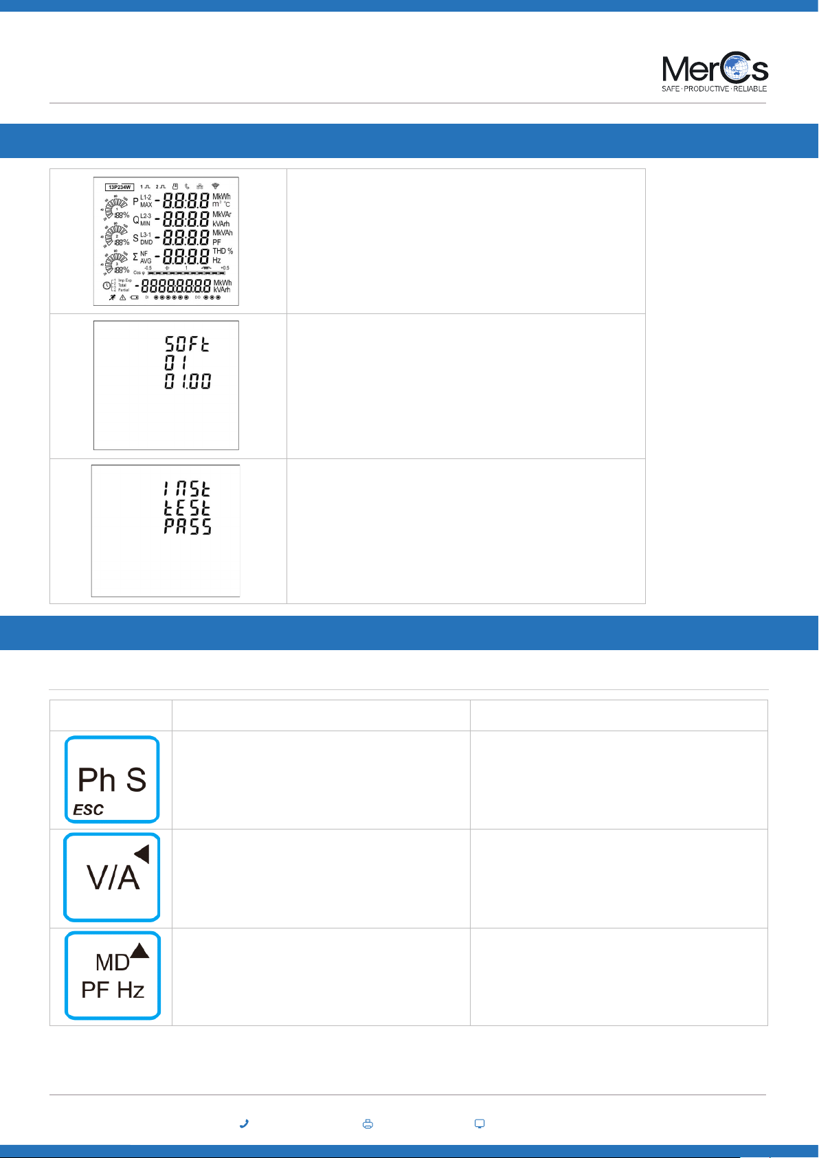
6. Start up screens
Image The rst screen lights all LED segments and can be used as a display LED
check
The second screen indicates the software version of the unit.
(the left picture is just for reference)
The unit performs a self-test and the screen indicates if the test is passed.
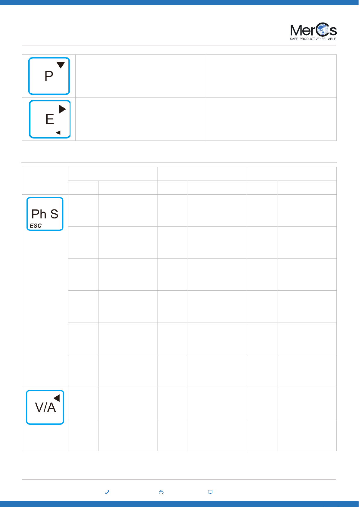
Buttons Click Press 2S
• Displays power, voltage, current and energy information
of each phase
• Exit from the menu
• Automatic Scroll display ON / OFF
• Display Voltage and current information of the selected
system type. (3p4w, 3p3w and 1p2w)
• Phase sequence
• Left side move
• Individual Harmonic Distortion of Voltage up to 63rd
• Display power factor, frequency, Max. Demand.
• Max. and Min. of current and voltage
• Up page or add value
• Individual Harmonic Distortion of Current up to 63rd
7. Buttons and Displays
Buttons Function
02 4047 0777 www.mercs.com.au02 4047 0788
MerCs Pty Ltd, 55 Pendlebury Rd, Cardi, NSW, 2285, Australia | 2018 V1.1
8
Strider M72 ME-PM-M72
• Display active power, reactive power and apparent
power information of the selected system type.
• Down page or reduce value
• Running hour
• Full Screen checking
• Modbus / Ethernet setting information
• Tari Information
• Display total / import / export active or reactive energy
information of the selected system type.
• Right side move
• Set-up mode entry
• Conrmation
Click button
3 Phase 4 Wire 3 Phase 3 Wire 1 Phase 2 Wire
Screen Parameters Screen Parameters Screen Parameters
1
Phase 1 – Power
Voltage
Current
kWh
1
Phase 1 – Power
Voltage
Current
kWh
1
Phase 1 – Power
Voltage
Current
kWh
2
Phase 2 – Power
Voltage
Current
kWh
2
Phase 2 – Power
Voltage
Current
kWh
3
Phase 3 – Power
Voltage
Current
kWh
3
Phase 3 – Power
Voltage
Current
kWh
4
Phase 1 – Power
Voltage
Current
kVarh
4
Phase 1 – Power
Voltage
Current
kVarh
2
Phase 1 – Power
Voltage
Current
kVarh
5
Phase 2 – Power
Voltage
Current
kVarh
5
Phase 2 – Power
Voltage
Current
kVarh
6
Phase 3 – Power
Voltage
Current
kVarh
6
Phase 3 – Power
Voltage
Current
kVarh
1
Voltage L1-N
Voltage L2-N
Voltage L3-N
1 Voltage L1-N
2
Voltage L1-L2
Voltage L2-L3
Voltage L3-L1
1
Voltage L1-L2
Voltage L2-L3
Voltage L3-L1
Display Mode Screen Sequence

02 4047 0777 www.mercs.com.au02 4047 0788
MerCs Pty Ltd, 55 Pendlebury Rd, Cardi, NSW, 2285, Australia | 2018 V1.1
9
Strider M72 ME-PM-M72
3
Current L1
Current L2
Current L3
Current Neutral
2
Current L1
Current L2
Current L3
2 Current L1
4
THD% of Voltage L1
THD% of Voltage L2
THD% of Voltage L3
3
THD% of Voltage L1-2
THD% of Voltage L2-3
THD% of Voltage L3-1
3 THD% of Voltage L1
5
THD% of Current L1
THD% of Current L2
THD% of Current L3
4
THD% of Current L1
THD% of Current L2
THD% of Current L3
4 THD% of Current L1
6 Phase Sequence 5 Phase Sequence
1Total Power Factor
Frequency 1Total Power Factor
Frequency 1Total Power Factor
Frequency
2
PF L1
PF L2
PF L3
2
PF L1
PF L2
PF L3
3
Max. DMD of Current L1
Max. DMD of Current L2
Max. DMD of Current L3
3
Max. DMD of Current L1
Max. DMD of Current L2
Max. DMD of Current L3
2 Max. DMD of Current L1
4
Max. DMD of W
Max. DMD of Var
Max. DMD of VA
4
Max. DMD of W
Max. DMD of Var
Max. DMD of VA
3
L1 Max. DMD of W
L1 Max. DMD of Var
L1 Max. DMD of VA
5
Max. Voltage L1-N
Max. Voltage L2-N
Max. Voltage L3-N
5
Max. Voltage L1-L2
Max. Voltage L2-L3
Max. Voltage L3-L1
4 Max. Voltage L1-N
6
Min. Voltage L1-N
Min. Voltage L2-N
Min. Voltage L3-N
6
Min. Voltage L1-L2
Min. Voltage L2-L3
Min. Voltage L3-L1
5 Min. Voltage L1-N
7
Max. Current L1
Max. Current L2
Max. Current L3
Max.Current Neutral
7
Max. Current L1
Max. Current L2
Max. Current L3
6 Max. Current L1
8
Min. Current L1
Min. Current L2
Min. Current L3
Min.Current Neutral
8
Min. Current L1
Min. Current L2
Min. Current L3
7 Min. Current L1

02 4047 0777 www.mercs.com.au02 4047 0788
MerCs Pty Ltd, 55 Pendlebury Rd, Cardi, NSW, 2285, Australia | 2018 V1.1
10
Strider M72 ME-PM-M72
1
Active Power L1
Active Power L2
Active Power L3
1
Active Power L1
Active Power L2
Active Power L3
2
Reactive Power L1
Reactive Power L2
Reactive Power L3
2
Reactive Power L1
Reactive Power L2
Reactive Power L3
3
Apparent Power L1
Apparent Power L2
Apparent Power L3
3
Apparent Power L1
Apparent Power L2
Apparent Power L3
4
Total Active Power
Total Reactive Power
Total Apparent Power
4
Total Active Power
Total Reactive Power
Total Apparent Power
1
L1 Active Power
L1 Reactive Power
L1 Apparent Power
1 Total kWh 1 Total kWh 1 Total kWh
2 Total kVarh 2 Total kVarh 2 Total kVarh
3 Import kWh 3 Import kWh 3 Import kWh
4 Export kWh 4 Export kWh 4 Export kWh
5 Import kVarh 5 Import kVarh 5 Import kVarh
6 Export KVarh 6 Export KVarh 6 Export KVarh
Individual Harmonic Distortion
Image Press the button for 2 seconds to check Harmonic distortion of Volt-
age 2~63rd Harmonic Distortion of Voltage
Press the button for 2 seconds to check Harmonic distortion of Cur-
rent 2~63rd Harmonic Distortion of Current

02 4047 0777 www.mercs.com.au02 4047 0788
MerCs Pty Ltd, 55 Pendlebury Rd, Cardi, NSW, 2285, Australia | 2018 V1.1
11
Strider M72 ME-PM-M72
8. Setting-Up
Password Entry
Image
Setting-up mode is password protected, so you must enter the correct password. By rmly press the
button for 2 seconds, the password screen appears. The default password is 1000. If an incorrect
password is entered, the display shows ERR.
02 4047 0777 www.mercs.com.au02 4047 0788
MerCs Pty Ltd, 55 Pendlebury Rd, Cardi, NSW, 2285, Australia | 2018 V1.1
12
Strider M72 ME-PM-M72
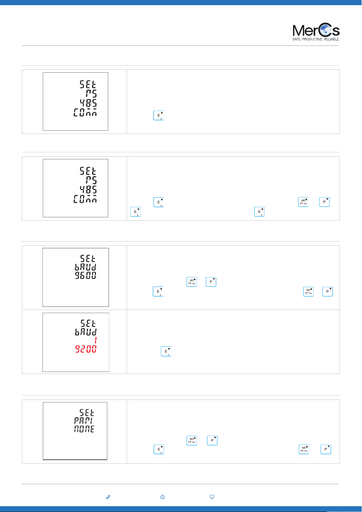
Communication
• Address
• Baud rate
Image
The RS485 port can be used for communications using Modbus RTU protocol. Parameters such as
Address, Baud rate, Parity, Stop bit can be selected.
Long press to enter the Address option.
Image
An RS485 network can accommodate up to 255 dierent devices, each identied by an address.
Modbus address range 001~247
Default 001
Long press to enter the selection routine, the address setting will ash. Use and ,
to set the address with the range 001~247. And press for conrmation.
Image
Baud rate options: 2400 4800 9600 19200 38400 (bps).
Default: 9600bps
From the Set-up menu, Use and to select the Baud rate options.
Long press to enter the selection routine. The Baud Rate setting will ash. Use and to
choose Baud Rate.
Example shows:
SET Baud rate 19200 (bps)
And long press for conrmation.
• Parity
Image
Parity Options: NONE, EVEN, ODD.
Default Parity : NONE
Note that if parity is set to ODD or EVEN, Stop Bits will be set to 1 and cannot be changed.
From the Set-up menu, Use and to select the Parity options.
Long press to enter the selection routine. The Parity setting will ash. Use and to
choose Parity.

02 4047 0777 www.mercs.com.au02 4047 0788
MerCs Pty Ltd, 55 Pendlebury Rd, Cardi, NSW, 2285, Australia | 2018 V1.1
13
Strider M72 ME-PM-M72
Image
Stop Bit options: 1 or 2.
Default Stop Bit : 1
Note that if parity is set to ODD or EVEN, Stop Bits will be set to 1 and cannot be changed.
From the Set-up menu, Use and to select the Stop Bit options.
Long press to enter the Stop Bit routine. The Stop Bit setting will ash. Use and to
choose Stop Bit.
Example shows
Set Stop bit 2
And long press for conrmation. Press to return the Communication set up menu.
• Stop bit
Example shows:
Set Parity: EVEN
And long press for conrmation. Press to return the main set up menu.
Example shows:
Set Parity: Odd
And long press for conrmation. Press to return the main set up menu
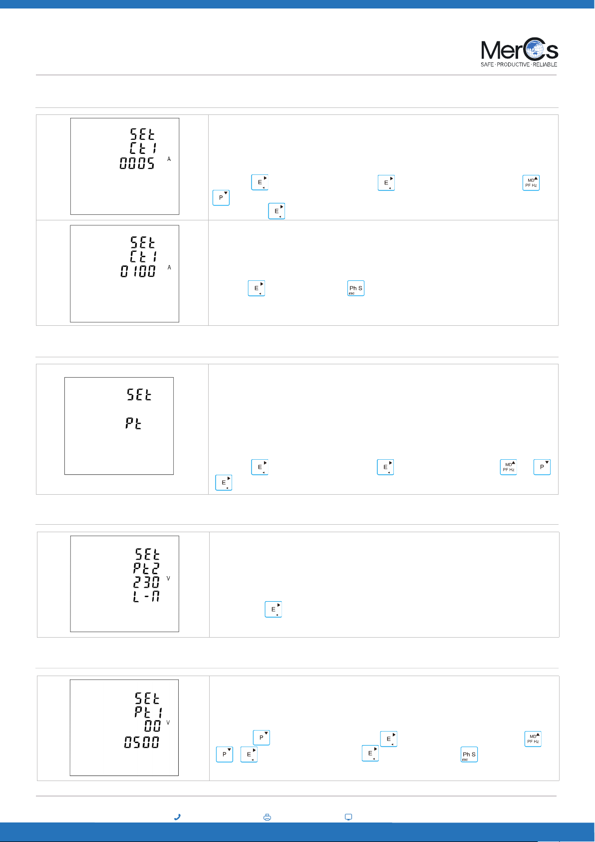
CT
Image From the main Set-up menu, Use and to select the CT option.
02 4047 0777 www.mercs.com.au02 4047 0788
MerCs Pty Ltd, 55 Pendlebury Rd, Cardi, NSW, 2285, Australia | 2018 V1.1
14
Strider M72 ME-PM-M72
Image
Set primary current input the meter
Options: 1~9999
Default CT1: 5A
Long press to enter the CT1 routine. Press for 2s, the CT1 setting will ash. Use and
to choose CT1 with 1~9999.
And long press for conrmation.
Example shows :
Set CT1 100A
And press for conrmation. Press to return the CT set up menu.
• CT1
PT
Image
The PT option sets the secondary voltage of the voltage transformer (PT) that give into the meter and
the PT rate between the primary voltage to the secondary voltage.
For example: if the PT connect to the meter is 10000/100V (Primary voltage is 10000V, secondary
voltage is 100V), then the PT rate is 100.
Long press to enter the PT2 routine. Press , the PT2 setting will ash. Use and ,
to choose PT2 with 174~480.
Set secondary voltage input the meter
Range: 100V ~ 480V
Default: 230V
And long press for conrmation.
Set primary voltage input the meter
Range: 100V ~ 500000V
Default: 230V
Then press to enter the PT2 routine. press for 2s, the PT2 setting will ash. Use and
, to select PT2. And long press for conrmation. Press to return the PT set
up menu.
• PT2
• PT1

02 4047 0777 www.mercs.com.au02 4047 0788
MerCs Pty Ltd, 55 Pendlebury Rd, Cardi, NSW, 2285, Australia | 2018 V1.1
15
Strider M72 ME-PM-M72
Demand
Image
This sets the period in minutes over which the current and power readings are integrated for maximum
demand measurement. The options are: OFF, 5, 8, 10, 15,30, 60 minutes.
From the Set-up menu, Use and to select the Demand option.
Slide Block: Select a demand interval time (DIT) from 1 to 60 minutes (in 1 minute increments). Set the calculation update time from 1 to 59minutes. The
power meter displays the demand value for the last completed interval.
Fixed Block: Select an interval from 1 to 60 minutes (in 1 minute increments). The power meter calculates an updates the demand at the end of each interval.
The screen shows the Demand calculation method: Slid
Options: Fix and Slid
Use and to enter Demand calculation method.
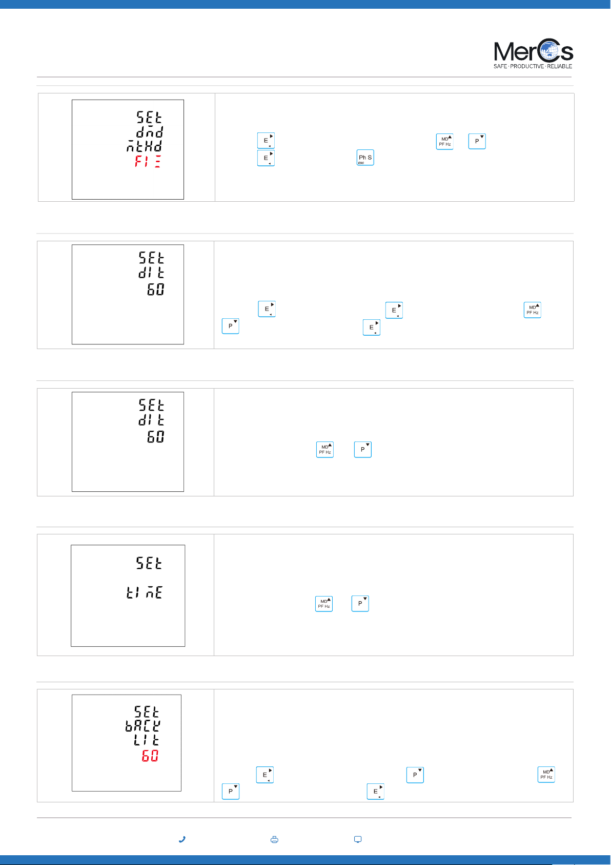
• Demand method
02 4047 0777 www.mercs.com.au02 4047 0788
MerCs Pty Ltd, 55 Pendlebury Rd, Cardi, NSW, 2285, Australia | 2018 V1.1
16
Strider M72 ME-PM-M72
Long press to enter the routine. The setting will ash. Use and to choose Options. And
long press for conrmation. Press to return the Demand set up menu.
• Demand interval time/ Block time (DIT)
Image
The screen will show the currently selected integration time.
Default is 60 minutes. range from 1 to 60. O means function closed.
Long press to enter the DIT routine. Press for 2s, the setting will ash. Use and
to choose Options. And long press for conrmation.
• Sliding time
Image This option sets the backlight lasting time and display scroll time.
From the Set-up menu, Use and to select the Time option.
• Backlight time
Image
The meter provides a function to set the backlit lasting time.
Options: ON/OFF/5/10/30/60/120 minutes. Default: 60
If it is seated as 5, the backlit will be o in 5 minutes.
Note: if it is set as ON, the backlit will always be on.
Long press to enter the Backlit time routine. Press for 2s, the setting will ash. Use and
to choose Options. And long press for conrmation.
Time
Image This option sets the backlight lasting time and display scroll time.
From the Set-up menu, Use and to select the Time option.

02 4047 0777 www.mercs.com.au02 4047 0788
MerCs Pty Ltd, 55 Pendlebury Rd, Cardi, NSW, 2285, Australia | 2018 V1.1
17
Strider M72 ME-PM-M72
• Display scroll time
Image
The meter provides a function to set the Display scroll time.
Options: 1~255s
Default: 5
If it is seated as 5, the display will scroll every 5s.
Use and to select Display scroll time option. Press for 2s, the setting will ash. Use
and to choose Options. And Long press for conrmation. Press to return the
Time set up menu.
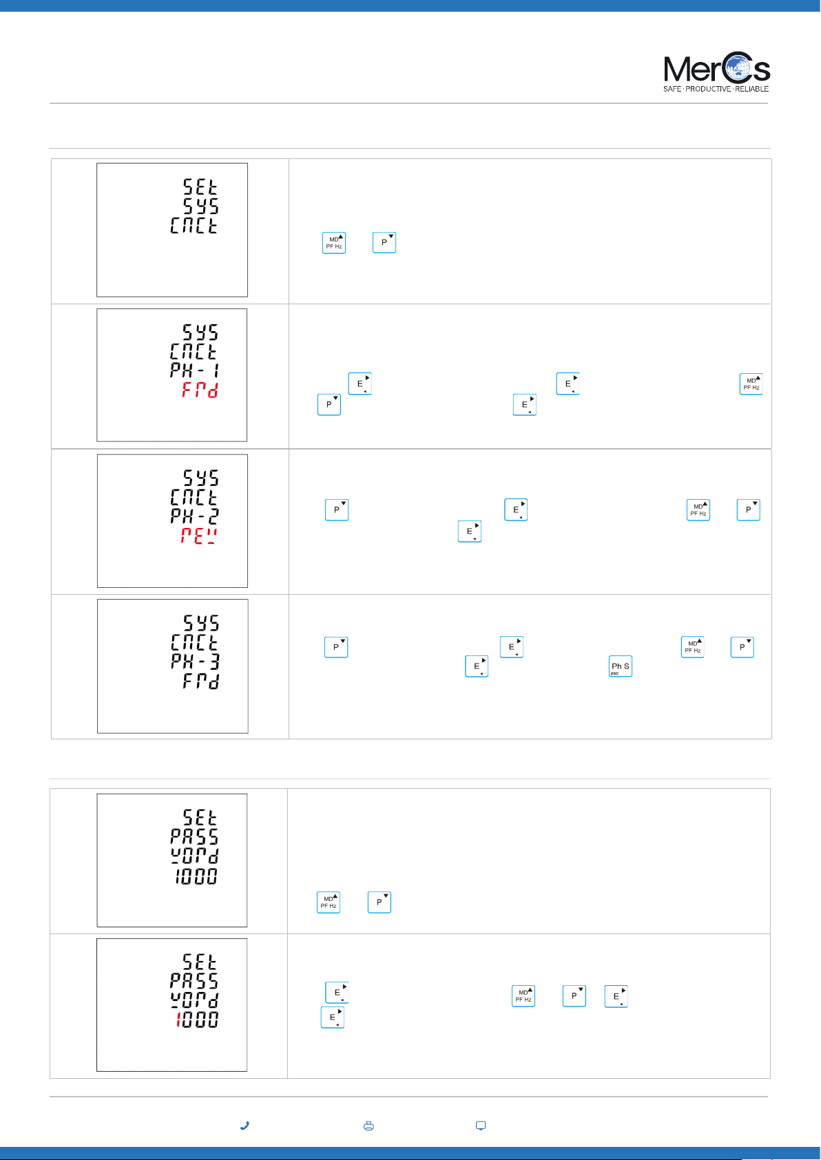
System
Image
The Unit has a default setting of 3 phase 4 wire ( 3p4w). Use this section to set the type of electrical
system.
Options: 3P4W, 3P3W, 1P2W
From the Set-up menu, Use and to select the System option
The screen shows the currently selected power supply is three phase four wire
Long press to enter the System type routine. Press for 2s, the setting will ash. Use
and to choose Options. And Long press for conrmation.
Example shows:
The screen shows the currently selected power supply is three phase three wire
Example shows:
The screen shows the currently selected power supply is single phase two wire
• System type
02 4047 0777 www.mercs.com.au02 4047 0788
MerCs Pty Ltd, 55 Pendlebury Rd, Cardi, NSW, 2285, Australia | 2018 V1.1
18
Strider M72 ME-PM-M72
This unit provides a function with Reverse connected current inputs correction setting.
Use and to select the correction option.
• System connect
Options: Frd ( forward ) and rEv ( reverse)
The default is FRD ( forward )
Long press to enter the Phase 1 correction. Press for 2s, the setting will ash. Use
and to choose Options. And long press for conrmation.
Press enter Phase 2 correction. Press for 2s, the setting will ash. Use and
to choose Options. And long press for conrmation.
Press enter Phase 3 correction. Press for 2s, the setting will ash. Use and
to choose Options. And long press for conrmation. Press to return the System set up
menu.
Image
This unit provides a function with password setting.
Default: 1000
Options:0000~99999
Use and to select the change password option.
Press for 2s, the setting will ash. Use and , to choose Options. And long
press for conrmation.
• Change password
02 4047 0777 www.mercs.com.au02 4047 0788
MerCs Pty Ltd, 55 Pendlebury Rd, Cardi, NSW, 2285, Australia | 2018 V1.1
19
Strider M72 ME-PM-M72
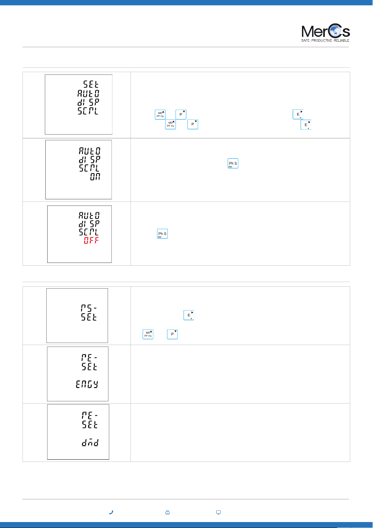
• Automatic display scroll
Image
This unit provides a function with automatic display scroll setting.
Options: on and o
There are two ways:
• Use and to select the automatic display scroll option. Press for 2s, the setting will
ash. Use and to choose options “On” or “O”. And long press for conrmation.
• Escape the Setting menu. Long press for 2 secs. For example, the screen shows the cur-
rently selected Automatic Scroll display ON.
Long press for 2 secs, then the screen shows the currently selected Automatic Scroll display OFF.
Reset
Image
This unit provides a function with reset for dierent information.
By pressing the button , the user can get into sub-menu.
Use and to select the Reset option
This option is to reset Energy information.
It would reset active, reactive, apparent, import, export energy information.
This option is to reset the demand information.
It would reset current and power demand information.
02 4047 0777 www.mercs.com.au02 4047 0788
MerCs Pty Ltd, 55 Pendlebury Rd, Cardi, NSW, 2285, Australia | 2018 V1.1
20
Strider M72 ME-PM-M72
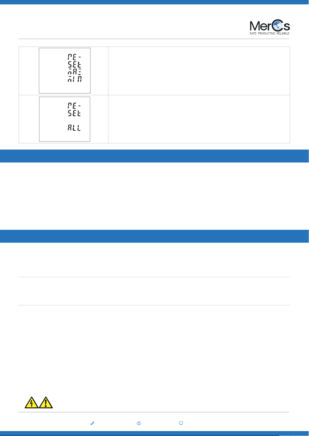
This option it to reset the Max. and Min. information
This option is to reset all information.
In normal use, little maintenance is needed. As appropriate for service conditions, isolate electrical power, inspect the unit and remove any dust
or other foreign material present. Periodically check all connections for freedom from corrosion and screw tightness, particularly if vibration is
present.
The front of the case should be wiped with a dry cloth only. Use minimal pressure, especially over the viewing window area. If necessary wipe the
rear case with a dry cloth. If a cleaning agent is necessary, isopropyl alcohol is the only recommended agent and should be used sparingly. Water
should not be used. If the rear case exterior or terminals should be contaminated accidentally with water, the unit must be thoroughly dried before
further use. Should it be suspected that water might have entered the unit, factory inspection and refurbishment is recommended.
In the unlikely event of a repair being necessary, it is recommended that the unit be returned to the factory or nearest MerCs distributor.
9. Maintenance
The unit may be mounted in a panel of any thickness up to a maximum of 3 mm. Leave enough space behind the instrument to allow for bends in
the connection cables. The unit is intended for use in a reasonably stable ambient temperature within the range -25°C to +55°C. Do not mount the
unit where there is excessive vibration or in excessive direct sunlight.
The unit is designed in accordance with IEC 61010-1:2010 – Permanently connected use, Normal condition. Installation category III, pollution degree
2, basic insulation for rated voltage.
Whilst this unit complies with all relevant EU EMC (electro-magnetic compatibility) regulations, any additional precautions necessary to provide
proper operation of this and adjacent equipment will be installation dependent and so the following can only be general guidance:
Avoid routing wiring to this unit alongside cables and products that are, or could be, a source of interference.
The auxiliary supply to the unit should not be subject to excessive interference. In some cases, a supply line lter may be required.
To protect the product against incorrect operation or permanent damage, surge transients must be controlled. It is good EMC practice to suppress
transients and surges at the source. The unit has been designed to automatically recover from typical transients; however in extreme circumstances
it may be necessary to temporarily disconnect the auxiliary supply for a period of greater than 10 seconds to restore correct operation.
Screened communication leads are recommended and may be required. These and other connecting leads may require the tting of RF suppression
components, such as ferrite absorbers, line lters etc., if RF elds cause problems.
10. Installation
Safety
EMC Installation Requirements
It is good practice to install sensitive electronic instruments that are performing critical functions in EMC enclosures that protect against electrical
interference causing a disturbance in function.
This manual suits for next models
3
Table of contents
Other MerCs Measuring Instrument manuals


Popular Measuring Instrument manuals by other brands


Campbell
Campbell CS320 product manual

Agilent Technologies
Agilent Technologies 4263B Configuration guide

Bosch
Bosch GLM 100 C Operating/safety instructions

General
General DCFM700 user manual

Elma Instruments
Elma Instruments Systronik FT30 user manual

Briggs & Stratton
Briggs & Stratton infohub 6574 installation instructions


