Geokon 4910 User manual

No part of this instruction manual may be reproduced, by any means, without the written consent of Geokon®.
The information contained herein is believed to be accurate and reliable. However, Geokon®assumes no responsibility for errors,
omissions or misinterpretation. The information herein is subject to change without notification.
Copyright © 2007-2019 by Geokon®
(Doc Rev B, 05/02/19)
Instruction Manual
Model 4910
Instrumented Rockbolt


Warranty Statement
Geokon warrants its products to be free of defects in materials and workmanship, under normal
use and service for a period of 13 months from date of purchase. If the unit should malfunction,
it must be returned to the factory for evaluation, freight prepaid. Upon examination by Geokon,
if the unit is found to be defective, it will be repaired or replaced at no charge. However, the
WARRANTY is VOID if the unit shows evidence of having been tampered with or shows
evidence of being damaged as a result of excessive corrosion or current, heat, moisture or
vibration, improper specification, misapplication, misuse or other operating conditions outside of
Geokon's control. Components which wear or which are damaged by misuse are not warranted.
This includes fuses and batteries.
Geokon manufactures scientific instruments whose misuse is potentially dangerous. The
instruments are intended to be installed and used only by qualified personnel. There are no
warranties except as stated herein. There are no other warranties, expressed or implied, including
but not limited to the implied warranties of merchantability and of fitness for a particular
purpose. Geokon is not responsible for any damages or losses caused to other equipment,
whether direct, indirect, incidental, special or consequential which the purchaser may experience
as a result of the installation or use of the product. The buyer's sole remedy for any breach of this
agreement by Geokon or any breach of any warranty by Geokon shall not exceed the purchase
price paid by the purchaser to Geokon for the unit or units, or equipment directly affected by
such breach. Under no circumstances will Geokon reimburse the claimant for loss incurred in
removing and/or reinstalling equipment.
Every precaution for accuracy has been taken in the preparation of manuals and/or software,
however, Geokon neither assumes responsibility for any omissions or errors that may appear nor
assumes liability for any damages or losses that result from the use of the products in accordance
with the information contained in the manual or software.


TABLE of CONTENTS
Instruction Manual...............................................................................................................................................1
MODEL 4910 .........................................................................................................................................................1
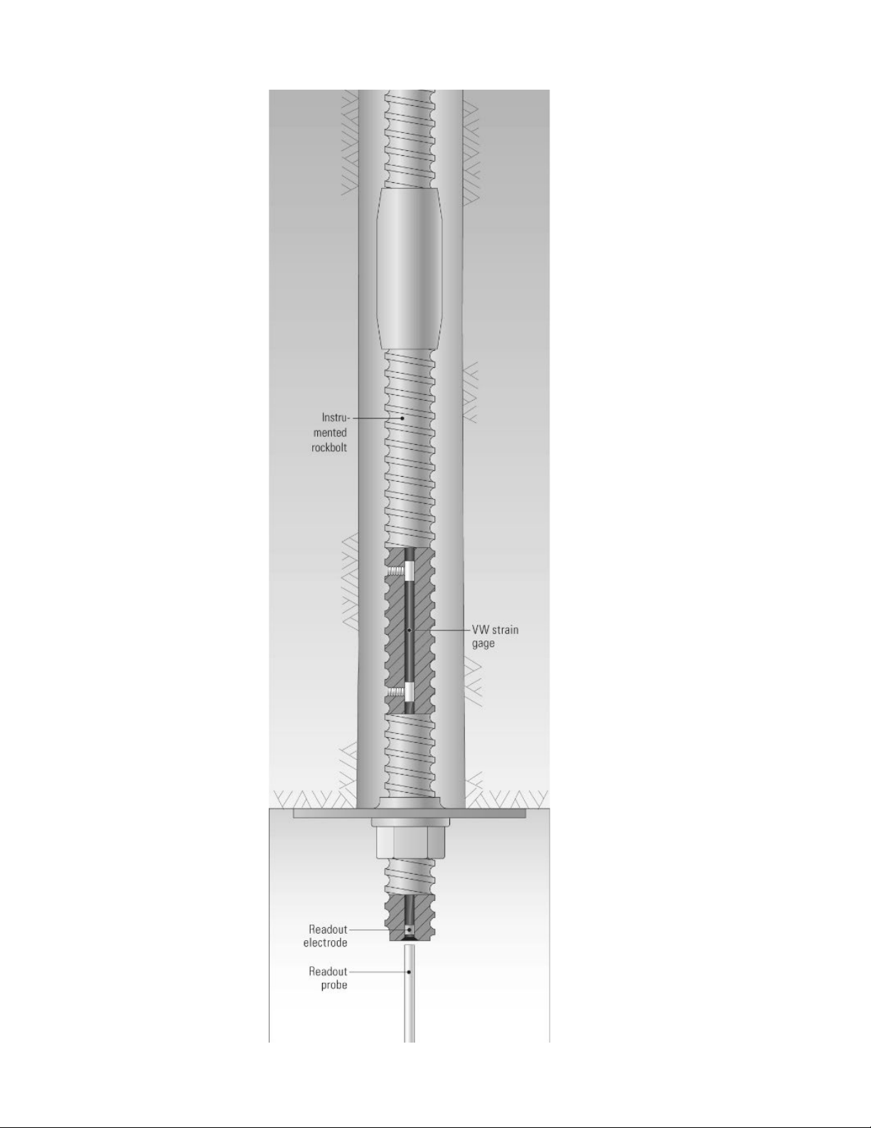
INSTRUMENTED ROCKBOLT ..............................................................................................................................1
1. INTRODUCTION ...................................................................................................................................................1
1.1 THEORY OF OPERATION.......................................................................................................................................1
2. INSTALLATION ....................................................................................................................................................3
2.1 PRELIMINARY TESTS............................................................................................................................................3
2.2 INSTRUMENTED ROCKBOLT INSTALLATION.........................................................................................................3
3. TAKING READINGS.............................................................................................................................................4
3.1 GK-404 READOUT BOX.......................................................................................................................................4
3.1.1 Operating the GK-404 ................................................................................................................................4
3.2 GK-405 READOUT BOX.......................................................................................................................................5
3.2.1 Connecting Sensors.....................................................................................................................................5
3.2.2 Operating the GK-405 ................................................................................................................................5
3.3 GK-403 READOUT BOX (OBSOLETE MODEL)......................................................................................................6
3.3.1 Connecting Sensors.....................................................................................................................................6
3.3.2 Operating the GK-403 ................................................................................................................................6
4. DATA REDUCTION ..............................................................................................................................................7
4.1 LOAD CALCULATION ...........................................................................................................................................7
4.2 TEMPERATURE CORRECTION FACTOR .................................................................................................................8
4.3 ENVIRONMENTAL FACTORS.................................................................................................................................8
5. TROUBLESHOOTING..........................................................................................................................................9
APPENDIX A. SPECIFICATIONS.........................................................................................................................10
A.1 SPECIFICATIONS................................................................................................................................................10
APPENDIX B. SAMPLE CALIBRATION REPORT ...........................................................................................11

FIGURES
FIGURE 1-THE 4910 READOUT PROBE USED WITH THE GK-404 READOUT.................................................................. 1
FIGURE 2-MODEL 4910 INSTALLATION........................................................................................................................ 2
FIGURE 3-LEMO CONNECTOR TO GK-404 ................................................................................................................... 4
FIGURE 4-LIVE READINGS –RAW READINGS............................................................................................................... 5
FIGURE 5-TYPICAL MODEL 4910 CALIBRATION REPORT............................................................................................11
TABLES
TABLE 1-ENGINEERING UNITS CONVERSION MULTIPLIERS ......................................................................................... 7
TABLE 2-MODEL 4910 INSTRUMENTED ROCKBOLT SPECIFICATIONS. ........................................................................10
EQUATIONS
EQUATION 1-DIGITS CALCULATION............................................................................................................................. 7
EQUATION 2-LOAD CALCULATION USING LINEAR REGRESSION ................................................................................. 7

1
1. INTRODUCTION
1.1 Theory of Operation
The Geokon Model 4910 Instrumented Rockbolt is made by inserting a vibrating wire strain
gauge inside a short length of standard threaded rockbolt or rebar. This short length is then
connected to a longer length of the same bolt material by means of a coupler. The full rockbolt
assembly is then installed in the normal manner, making sure that the strain gauged portion of
the bolt remains located in the loaded section of the bolt.
The Instrumented Rockbolt is frequently used:
•To confirm the load as determined by the torque applied to the rockbolt nut, or to the
hydraulic pressure exerted by a jack, during installation
•To provide a permanent means of monitoring the load throughout the life of the rockbolt.
The Instrumented Rockbolt is read out by means of a hand-held Readout Probe that is used to
contact an electrode in the end of the bolt. The probe is shown in Figure 1. The probe is
connected to a readout box and then the tip of the probe is pushed against the electrode recessed
in the end of the rockbolt. This method of readout eliminates the need for cables and connectors,
which could be damaged during installation or later.
Figure 1 - The 4910 Readout Probe used with the GK-404 Readout.
Figure 2 on the following page shows a typical installation.

2
Figure 2 - Model 4910 Installation

3
2. INSTALLATION
2.1 Preliminary Tests
Before installing the Instrumented Rockbolt, it should be checked by connecting it to the readout
box and taking a no-load reading. This reading, when compared with that given in the calibration
data provided with the load cell, will show if the sensor is functioning properly. The two
readings should agree within about ±50 digits. See Section 3 for readout instructions.
Before installing the Instrumented Rockbolt be sure to take the no-load reading. This reading is
very important since it is the reading that will be subtracted from all subsequent readings to
calculate the load. Note that each Instrumented Rockbolt has a different no-load reading, which
is not zero. See Section 3 for operation of the Readout Boxes.
2.2 Instrumented Rockbolt Installation
Connect the instrumented section to the rest of the rockbolt using the coupler provided make sure
that the electrode end points out of the end of the bolt. Tighten the connector then install the bolt
in the normal manner being sure to position the nut and bearing plate so that the strain gauge
inside the Instrumented Rockbolt is positioned inside the borehole so that it will experience the
full load in the bolt. Do not run the nut up so far that it lies over the strain gauge.

4
3. TAKING READINGS
3.1 GK-404 Readout Box
The Model GK-404 Vibrating Wire Readout is a portable, low-power, handheld unit that can run
continuously for more than 20 hours on two AA batteries. It is designed for the readout of all
Geokon vibrating wire gauges and transducers; and is capable of displaying the reading in either
digits, frequency (Hz), period (µs), or microstrain (µε).
3.1.1 Operating the GK-404
Before use, attach the flying leads to the GK-404 by aligning the red circle on the silver
“Lemo” connector of the flying leads with the red line on the top of the GK-404 (Figure
3). Insert the Lemo connector into the GK-404 until it locks into place.
Figure 3 - Lemo Connector to GK-404
Connect each of the clips on the leads to the matching colors of the sensor conductors,
with blue representing the shield (bare).
To turn the GK-404 on, press the “ON/OFF” button on the front panel of the unit. The
initial startup screen will be displayed. After approximately one second, the GK-404 will
start taking readings and display them based on the settings of the POS and MODE
buttons.
The unit display (from left to right) is as follows:
•The current Position: Set by the POS button. Displayed as a letter A through F.
•The current Reading: Set by the MODE button. Displayed as a numeric value
followed by the unit of measure.
•Temperature reading of the attached gauge in degrees Celsius.
Use the POS button to select position B and the MODE button to select Dg (digits).
(Other functions can be selected as described in the GK-404 Manual.)
The GK-404 will continue to take measurements and display readings until the unit is
turned off, either manually, or if enabled, by the Auto-Off timer. If the no reading
displays or the reading is unstable, see Section 5 for troubleshooting suggestions.
For further information, please see the GK-404 manual.

5
3.2 GK-405 Readout Box
The GK-405 Vibrating Wire Readout is made up of two components: The Readout Unit,
consisting of a Windows Mobile handheld PC running the GK-405 Vibrating Wire Readout
Application; and the GK-405 Remote Module, which is housed in a weatherproof enclosure and
connects to the vibrating wire gauge to be measured. The two components communicate
wirelessly. The Readout Unit can operate from the cradle of the Remote Module, or, if more
convenient, can be removed and operated up to 20 meters from the Remote Module.
3.2.1 Connecting Sensors
Connecting sensors with 10-pin connectors:
Align the grooves on the sensor connector (male), with the appropriate connector on the
readout (female connector labeled senor or load cell). Push the connector into place, and
then twist the outer ring of the male connector until it locks into place.
Connecting sensors with bare leads:
Attach the GK-403-2 flying leads to the bare leads of a Geokon vibrating wire sensor by
connecting each of the clips on the leads to the matching colors of the sensor conductors,
with blue representing the shield (bare).
3.2.2 Operating the GK-405
Press the button labeled “POWER ON”. A blue light will begin blinking, signifying that
the Remote Module is waiting to connect to the handheld unit. Launch the GK-405
VWRA program by tapping on “Start” from the handheld PC’s main window, then
“Programs” then the GK-405 VWRA icon. After a few seconds, the blue light on the
Remote Module should stop flashing and remain lit. The Live Readings Window will be
displayed on the handheld PC. Choose display mode “B”. Figure 4 shows a typical
vibrating wire output in digits. If no reading displays or the reading is unstable, see
Section 5 for troubleshooting suggestions. For further information, consult the GK-405
Instruction Manual.
Figure 4 - Live Readings – Raw Readings

6
3.3 GK-403 Readout Box (Obsolete Model)
The GK-403 can store gauge readings and apply calibration factors to convert readings to
engineering units. The following instructions explain taking gauge measurements using Mode
“B”. Consult the GK-403 Instruction Manual for additional information.
3.3.1 Connecting Sensors
Connecting sensors with 10-pin connectors:
Align the grooves on the sensor connector (male), with the appropriate connector on the
readout (female connector labeled senor or load cell). Push the connector into place, and
then twist the outer ring of the male connector until it locks into place.
Connecting Sensors with Bare Leads:
Attach the GK-403-2 flying leads to the bare leads of a Geokon vibrating wire sensor by
connecting each of the clips on the leads to the matching colors of the sensor conductors,
with blue representing the shield (bare).
3.3.2 Operating the GK-403
1) Turn the display selector to position “B”.
2) Turn the unit on.
3) The readout will display the vibrating wire output in digits. The last digit may change
one or two digits while reading.
4) Press the “Store” button to record the value displayed.
If the no reading displays or the reading is unstable, see Section 5 for troubleshooting
suggestions. The unit will turn off automatically after approximately two minutes to
conserve power.

7
4. DATA REDUCTION
4.1 Load Calculation
The basic units utilized by Geokon for measurement and reduction of data from Instrumented
Rockbolts are "digits". Calculation of digits is based on the following equation:
Digits = 1
Period2
x 10-3 or Digits=Hz2
1000
Equation 1 - Digits Calculation
To convert the digits readings to load, the gauge readings for each cell must be multiplied by the
gauge factor supplied with the Instrumented Rockbolt.
L = (R1– R0) ×G ×K
Equation 2 - Load Calculation Using Linear Regression
Where;
L is the load in lbs. or kg. etc.
R0is the regression no-load reading in digits s supplied on the calibration report. (A sample
calibration report is given in Appendix B.)
R1is the current reading in digits
G is the gauge factor as supplied on the calibration report.
K is the conversion factor (optional) as listed in Table 1.
From→
To↓
Lbs.
Kg.
Kips
Tons
Metric
Tonnes
Lbs.
1
2.205
1000
2000
2205
Kg.
0.4535
1
453.5
907.0
1000
Kips
0.001
0.002205
1
2.0
2.205
Tons
0.0005
0.0011025
2.0
1
1.1025
Metric
Tonnes
0.0004535
0.001
0.4535
0.907
1
Table 1 - Engineering Units Conversion Multipliers
For example:
If;
R0= 7138
R1= 8500
G = 8.092 .lbs per digit
Then;
L = (8500 −7138) ×8.092 = 11,020 lbs.

8
Note that the equations assume a linear relationship between load and gauge readings over the
full load range, and the linear coefficient is obtained using regression techniques. Note that
when using the Calibration Factor obtained from the regression formula it is better to use
the regression zero. This may introduce substantial errors at very low loads. A measure of
the amount of non-linearity is shown on the calibration report in the column entitled “Linearity”.
4.2 Temperature Correction Factor
Since the vibrating wire has the same temperature coefficient as the steel rockbolt no temperature
correction is required.
4.3 Environmental Factors
Since the purpose of the instrumented rockbolt installation is to monitor site conditions, factors
which may affect these conditions should be observed and recorded. Seemingly minor effects
may have a real influence on the behavior of the rock strata monitored and may give an early
indication of potential problems. Some of these factors include, but are not limited to: blasting,
rainfall, tidal or reservoir levels, excavation and fill levels and sequences, traffic, temperature
and barometric changes, changes in personnel, nearby construction activities, seasonal changes,
etc.

9
5. TROUBLESHOOTING
Problems with the instrumented rockbolt are usually associated with dirty electrodes.
Symptom: Instrumented Rockbolt Readings are Unstable:
Is the readout box position set correctly? (Use Channel B.)
Does the readout work with another instrumented rockbolt? If not, the readout may have a
low battery or be malfunctioning.
Symptom: Instrumented Rockbolt Fails to Read:
Is the electrode covered with dirt? Clean the electrode with a swab attached to the readout
probe. Use electro contact cleaner or similar product.
Does the readout or datalogger work with another Instrumented rockbolt? If not, the readout
or datalogger may be malfunctioning.

10
APPENDIX A. SPECIFICATIONS
A.1 Specifications
Available Ranges:
2500 microstrain (equivalent to 27,000 kg in a 25 mm diameter
bolt)
Accuracy:
±0.25% FS
Linearity:
0.5% FSR
Resolution:
0.5 microstrain (equivalent to 5 kg in a 25 mm dia. bolt)
Repeatability:
0.1% FSR
Temperature Effect:
zero
Temperature Range:
−40 to +80° C
-40 to 110° F
Frequency Output Range
1400-3000 Hz
Over-range:
150%
Bolt Size
25 mm or #8 rebar and larger.
Length
300 mm (standard) (other lengths are optional)
Table 2 - Model 4910 Instrumented Rockbolt Specifications.

11
APPENDIX B. SAMPLE CALIBRATION REPORT
Figure 5 - Typical Model 4910 Calibration Report
Table of contents
Other Geokon Measuring Instrument manuals
Popular Measuring Instrument manuals by other brands

Lutron Electronics
Lutron Electronics MHT-381SD Operation manual

YSI
YSI ProDSS Calibration and Routine Maintenance

Rice Lake
Rice Lake 480 Legend Series Operation manual

New Focus
New Focus Vortex 6000 Series user guide

MEASUREMENT TECHNOLOGY
MEASUREMENT TECHNOLOGY LCI-90 installation manual

Victor
Victor 86B manual