Merlin Swing L 300 MGL Series User manual

This manual containsIMPORTANT SAFETY information
DO NOT PROCEED WITH THE INSTALLATION BEFORE READING THOROUGHLY
MGLX
Linear Actuator Gate Opener
(MGLSK / MGLDK / MGLSK-LV / MGLDK-LV)
Installation and Operating Instructions
Owners Copy: SAVE THESE INSTRUCTIONS for future reference
gomerlin.com.au
gomerlin.co.nz
Visit the Swing L 300 landing pages for:
• Product features
• Purchase compatible accessories
• Handy tips & how-to videos
• Digital copy of this manual
• Register your warranty

2
SAFETY INSTRUCTIONS
WARNING!
START BY READING THESE IMPORTANT SAFETY INSTRUCTIONS
ST
About this Manual
These instructions are the original operating instructions according to the AS/NZS 60335.1 in conjunction with AS/NZS 60335.2.103.
The instruction manual must be read carefully to understand important product information. Pay attention to the safety and warning
notices.
Keep the instructions in a safe place and make sure that they can be viewed by the user at all times. Keep the manual for future
reference and to make it available to all persons for inspection, service, maintenance and repair. After installation pass the complete
documentation to the owner.
After installation and programming, all users must be instructed in the function and operation of the gate opener for correct and safe
operation.
Before first use and based on the standard requirements the installer must inspect gates regarding their safe condition.
Before you begin the installation:
This product must be installed by a professional installer.
The installer must understand the following:
• The operation of the drive and potential hazards
• The operation of the manual emergency release mechanism
• The regular maintenance, inspection and care according to the Standards
• The installer must instruct other uses on the safe operation of the gate opener
Please read the operating instructions and especially the precautions. The following symbols are placed in front of instructions to avoid
personal injury or damage to property. Read these instructions carefully.
Warning Symbols
The general warning symbol indicates a danger that can lead to injuries or death. In the text section, the general warning symbols are
used as described below.
DANGER Symbol WARNING Symbol CAUTION Symbol ATTENTION Symbol
Indicates an imminent
hazardous situation which, if not
avoided, will result in death or
serious injury.
Indicates a potentially hazardous
situation which, if not avoided,
could result in death or serious
injury.
Indicates a potentially hazardous
situation which, if not avoided,
could result in minor or
moderate injury.
Indicates practices not
related to personal injury.
Intended Use
The gate opener is exclusively designed and tested for the operation of smooth-running residential gates.
The maximum permissible gate size and the maximum weight must not be exceeded. The gate must open and close smoothly by
hand. Use the opener on gates which comply with the applicable standards and guidelines. Regional conditions of wind loads must
be taken into account when using door or gate panels. Observe the manufacturer’s specifications regarding the combination of gate
and opener. Possible hazards within the meaning of AS/NZS 60335.1 in conjunction with AS/NZS 60335.2.103 are to be avoided
by designing and installing the gate according to the relevant instructions. This gate mechanism must be installed and operated in
accordance with the appropriate safety rules.
Improper Use
The construction of the gate opener is not designed for the operation of heavy-duty gates. It is not permitted on gates that travel with
incline/decline.
Any improper use of the gate opener could increase the risk of accidents. The manufacturer assumes no liability for such usage. With
this gate opener, automated gates must comply with the current, valid local standards, guidelines and regulations, AS/NZS 60335.1 in
conjunction with AS/NZS 60335.2.103.
Only Merlin genuine and approved accessories may be connected to the gate opener. Incorrect installation and/or failure to comply
with the following instructions may result in serious personal injury or damage to property.
DANGER WARNING CAUTION ATTENTION
• Failure to comply with the following instructions may result in serious personal injury or property damage.
• Read and follow all instructions carefully.
• The gate opener is designed and tested to offer safe service, provided it is installed and operated in strict accordance with the
instructions in this manual.

3
SAFETY INSTRUCTIONS
During operation, the gate should not under any circumstances obstruct public path ways and roads (public area). When using tools
and small parts to install or carry out repair work on a gate, exercise caution and do not wear rings, watches or loose clothing.
To avoid serious personal injury due to entrapments, remove any locking device fitted to the gate in order to prevent damage to the
gate.
Installation and wiring must be in compliance with your local building and electrical installation regulations. Power cables must only be
connected to a properly earthed supply.
Disconnect electric power to the system before installation, maintenance, repairs or removing covers. A dual pole isolating switch
must be provided to the mains power supply (permanently-wired installation) to guarantee all-pole disconnection (isolating switch or by
a separate fuse). The repairs and electrical installations may be performed only by an authorized electrician. Emergency Stop Button
must be installed for emergency case based on the risk assessment.
Any possible entrapment caused by the moving gate leaf(s) between gate & walls must be eliminated by respecting the given safety
distances in accordance with the AS/NZS 60335.1 in conjunction with AS/NZS 60335.2.103 and/or with safety devices (e.g. safe
edge).
Testing of the safety function of the drive system is recommended to be carried out at least once a month. Refer also to
manufacturers instruction of the gate system components.
After the installation a final test of the full function of the system and the safety devices must be made.
After installation and commissioning, all users must be instructed in the function and operation of the swing gate opener.
It is important to make sure that the gate always runs smoothly. Gates which stick or jam must be repaired immediately. Employ a
qualified technician to repair the gate, never attempt to repair it yourself. This device is not intended for use by persons (including
children) with restricted physical, sensory or mental abilities or lack of experience or knowledge, unless they are supervised by a
person responsible for their safety or have received instruction in how to use the device. If necessary, control equipment MUST be
mounted within sight of the gate and out of reach of children. Children should be supervised to ensure that they do not play with the
device. Do not allow children to operate push button(s) or remote(s). Misuse of the gate opener system can result in serious injury.

4
CONTENTS
1
2345
678
910 11
12
13
Manual
14
Quick
Reference
guide
15
SAFETY INSTRUCTIONS ........................................................................................................................................... 2-3
INTRODUCTION ....................................................................................................................................................... 5-10
Specifications .........................................................................................................................................................................................5
Sales Kit Inventory.............................................................................................................................................................................. 5-6
Tools Needed.........................................................................................................................................................................................7
Overview of Gate Operator.....................................................................................................................................................................7
Planning ........................................................................................................................................................................................... 8-10
INSTALLATION ....................................................................................................................................................... 11-14
Post Bracket Installation .......................................................................................................................................................................11
Gate Bracket Installation.......................................................................................................................................................................11
Hard Stops Installation .........................................................................................................................................................................12
Release Mechanism .............................................................................................................................................................................12
Install the Control Box ..........................................................................................................................................................................13
WIRING .................................................................................................................................................................... 14-16
Electrical Safety....................................................................................................................................................................................14
Opener 1 and Opener 2 Connection ....................................................................................................................................................14
Wiring Diagram.....................................................................................................................................................................................15
Install Entrapment Protection Devices ..................................................................................................................................................16
Connect a Battery Backup to the Control Box (Optional)......................................................................................................................16
PROGRAMMING ..................................................................................................................................................... 17-19
LCD Screen Menu................................................................................................................................................................................17
Programming Overview .................................................................................................................................................................. 17-18
Initial Setup...........................................................................................................................................................................................19
BASIC SETTINGS.................................................................................................................................................... 20-25
Limit and Force Learning......................................................................................................................................................................20
Remote Control Behaviour ...................................................................................................................................................................20
IR Behaviour.........................................................................................................................................................................................20
Input Command ...................................................................................................................................................................................21
Pedestrian Command...........................................................................................................................................................................21
Delay Motor 2 in Open and Close Direction.................................................................................................................................... 21-22
Timer To Close (TTC)............................................................................................................................................................................22
Reversal Time.......................................................................................................................................................................................23
E-Lock & Ram Blow Motor 1 for E-Lock ........................................................................................................................................ 23-24
Flashing Light - Pre-Flashing ................................................................................................................................................................24
Special Contact....................................................................................................................................................................................25
Soft & Hard Stop in Open and Close Direction.....................................................................................................................................25
Maintenance Counter ...........................................................................................................................................................................25
ADVANCED SETTINGS .......................................................................................................................................... 26-29
Password ............................................................................................................................................................................................26
Force Motors 1 & 2 Open and Close (Password Protected) ................................................................................................................27
Speed Motors 1 & 2 in Open and Close Direction (Password Protected) .............................................................................................28
Soft-Stop Speed in Open and Close Direction (Password Protected)...................................................................................................28
FACTORY RESET .........................................................................................................................................................29
WIRELESS PROGRAMMING ................................................................................................................................. 30-33
Remote Control Programming..............................................................................................................................................................30
MyQ Set-up.................................................................................................................................................................................... 31-33
OPERATION AND MAINTENANCE ....................................................................................................................... 34-37
Error Codes.................................................................................................................................................................................... 34-35
Accessories and Gate Hardware .................................................................................................................................................... 36-37
PROGRAMMING FLOW CHART............................................................................................................................ 38-42
CHAMBERLAIN LIMITED WARRANTY ................................................................................................................. 43-44

5
INTRODUCTION
Main AC Supply:…….…………………...........……….……………..220-240 Vac; 50/60 Hz
Motor Voltage: …………..…………………..........………………….24 Vdc
Input Power (single arm): .…………..…………………..........……50 W
Ambient Temperature Range: …………..…………………...........-20 ~ +55˚C
Maximum Weight for single Gate.........…………..……………… 300 kg/2 m, 250 kg/2.5 m, 200 kg/3 m
Maximum Width for single Gate ........…………..………………...1.8 m, 2.5 m
Maximum Pull Force:…………………………….............………….1500 N
Maximum Open Angle: …………..…………………..........………..120˚
Running Time: ................…………..…………………..........……….5 minutes
Ingress Protection:…………..…………….…..........……………….IP 44 (Opener MGLX), IP 65 (Control Box MGEB) Suitable for
outdoor installation
Transmitter Frequency: …………..…………………..........……….433.30 MHz/ 433.92 MHz/ 434.54 MHz
Memory registers:….....................................………………………64 handset codes (max. 4 keypad devices - 1 code each.)
Dimensions
Gate Opener Height:…………………………….............…………..137 mm
Gate Opener Width:………..…………………….............………….835 mm
Gate Opener Depth:…………………………….............…………...95 mm
Gate Opener Weight:…………………………….............………….6 kg
SPECIFICATIONS – SWING L 300 – MGLSK / MGLDK / MGLSK-LV / MGLDK-LV
1
1
2345
678
910 11
12
13
Manual
14
Quick
Reference
guide
15
SALES KIT INVENTORY - MGLSK MAINS VOLTAGE 240V OR MGLSK-LV LOW VOLTAGE
24V SWING GATE OPENER LINEAR ACTUATOR SINGLE KIT
2
(1) Opener (MGLX)
(2) Control Box (MGEB)
(3) Instruction Manual
(4) 2 x Release Keys
(5) Fixed Post Bracket
(6) Live Post Bracket
(7) Hairpin Clip
(8) Clevis Pin
(9) 4 x M8x60 Masonry Anchors
(10) Gate Mounting Bracket
(11) 2 x M10x30 Bolts
(12) 13mm Bolt and Washer
(13) 2 x Four Button Remotes (E970M)
(14) Quick Reference Guide
(15) Gate Transformer 240-24V 120VA (MGTR3-120VA)
NOTE: Only for low voltage MGLSK-LV sales kit.
Your gate opener is packed in separate cartons. The Swing L 300 MGLSK or MGLSK-LV opener sales kit contains the opener, its
hardware, accessories and a transformer MGTR3-120VA (only for the MGLSK-LV sales kit).

6
INTRODUCTION
12345
678
9
10 11
12 13
Manual
14
Quick
Reference
guide
15
SALES KIT INVENTORY - MGLDK MAINS VOLTAGE 240V OR MGLDK-LV LOW VOLTAGE
24V SWING GATE OPENER LINEAR ACTUATOR DUAL KIT
2
(1) 2 x Opener (MGLX)
(2) Control Box (MGEB-LV)
(3) Instruction Manual
(4) 4 x Release Keys
(5) 2 x Fixed Post Bracket
(6) 2 x Live Post Bracket
(7) 2 x Hairpin Clip
(8) Clevis Pin
(9) 8 x M8x60 Masonry Anchors
(10) 2 x Gate Mounting Bracket
(11) 4 x M10x30 Bolts
(12) 2 x 13mm Bolt and Washer
(13) 2 x Four Button Remotes (E970M)
(14) Quick Reference Guide
(15) Gate Transformer 240-24V 120VA (MGTR3-120VA)
NOTE: Only for low voltage MGLDK-LV sales kit.
Your gate opener is packed in separate cartons. The Swing L 300 MGLDK or MGLDK-LV opener sales kit contains the opener, its
hardware, accessories and a transformer MGTR3-120VA (only for the MGLDK-LV sales kit).
7
TOOLS NEEDED
3
INTRODUCTION
MGLSK – MAINS VOLTAGE 240V SWING GATE OPENER LINEAR ACTUATOR SINGLE KIT OR
MGLSK-LV – LOW VOLTAGE 24V SWING GATE OPENER LINEAR ACTUATOR SINGLE KIT
MGLDK – MAINS VOLTAGE 240V SWING GATE OPENER LINEAR ACTUATOR DUAL KIT OR
MGLDK-LV – LOW VOLTAGE 24V SWING GATE OPENER LINEAR ACTUATOR DUAL KIT
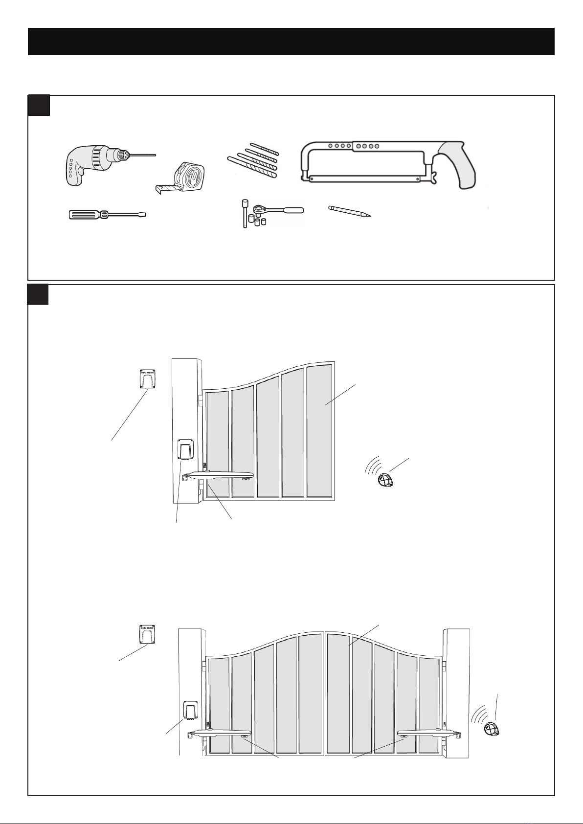
OVERVIEW OF THE GATE OPENER
4
Gate Opener
(MGLX)
Remote
Control
Single
Swing Gate
Control Box
(MGEB or MGEB-LV)
Control Box
(MGEB or
MGEB-LV) Gate Opener (MGLX)
Remote
Control
Double
Swing Gate
T
ransformer Box
mounted near 240V
power supply
(MGTR3-120VA)
NOTE: Only required
for MGLSK-LV low
voltage 24V sales kit
Transformer Box
mounted near 240V
power supply
(MGTR3-120VA)
NOTE: Only required
for MGLDK-LV
low voltage 24V
sales kit
8
INTRODUCTION
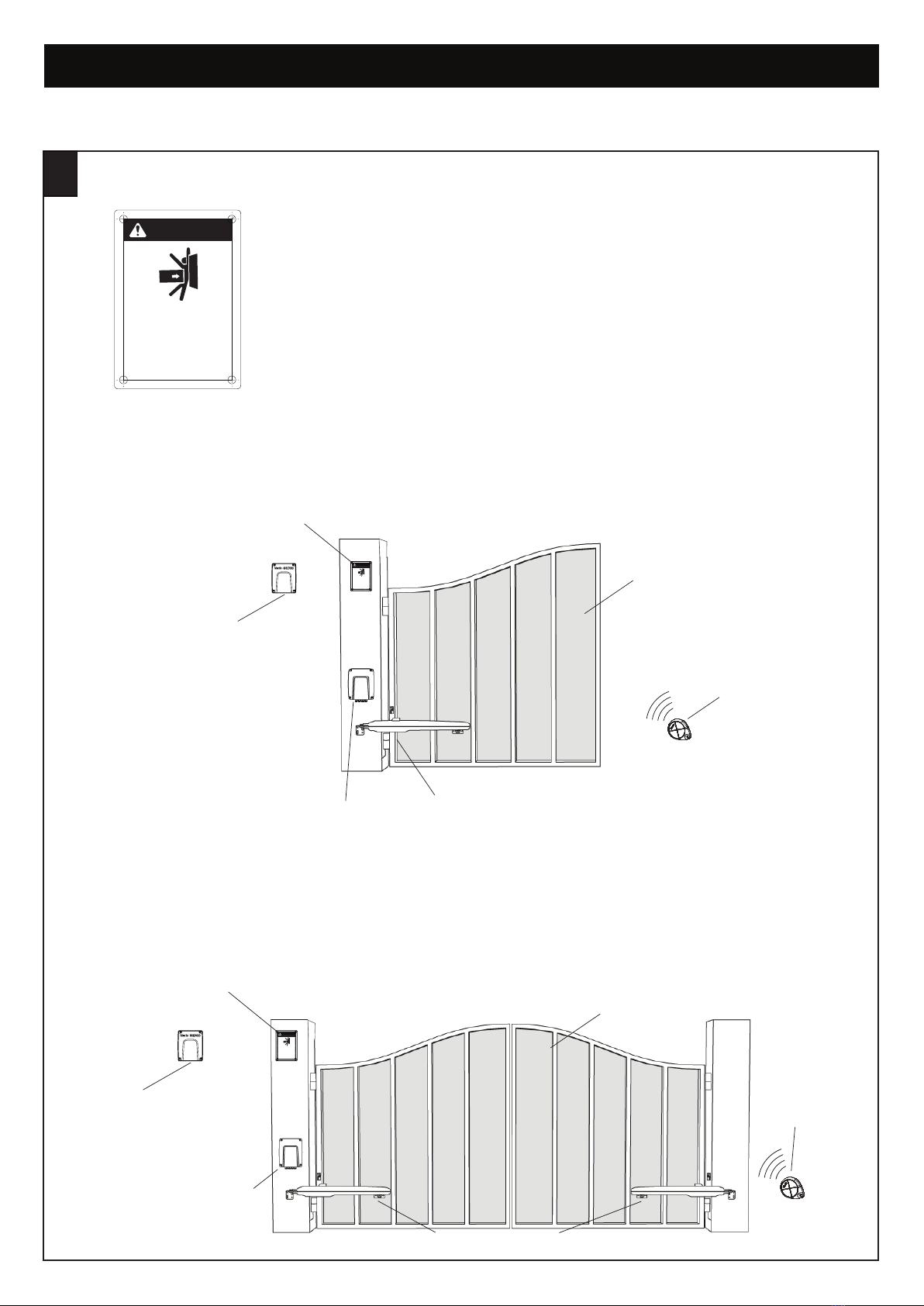
Warning Label is provided with each sales kit (MGLSK, MGLDK,
MGLSK-LV & MGLDK-LV). The warning label must be placed on the
inside of the post.
INSTALLING THE WARNING LABELS
5
Persons are to keep clear! The gate is able to
be moved without prior warning.
Do not let children operate the gate or play in
the gate area.
Moving Gate Can Cause
Serious Injury Or Death
WARNING
132A3224-01
Gate Opener
(MGLX)
Remote
Control
Single
Swing Gate
Control Box
(MGEB or MGEB-LV)
Control Box
(MGEB or
MGEB-LV) Gate Opener (MGLX)
Remote
Control
Double
Swing Gate
Warning Label
placed within
the inside of
the post
Personsare to keep clear! The gate is able to
bemoved without prior warning.
Donot let children operate the gate or play in
thegate area.
Moving Gate Can Cause
Serious Injury Or Death
132A3224-01
WARNING
Warning Label
placed within
the inside of
the post
Personsare to keep clear! The gate is able to
bemoved without prior warning.
Donot let children operate the gate or play in
thegate area.
Moving Gate Can Cause
Serious Injury Or Death
132A3224-01
WARNING
Transformer Box
mounted near 240V
power supply
(MGTR3-120VA)
NOTE: Only required
for MGLDK-LV
low voltage 24V
sales kit
Transformer Box
mounted near 240V
power supply
(MGTR3-120VA)
NOTE: Only required
for MGLDK-LV
l
ow voltage 24V
sales kit
MGLSK – MAINS VOLTAGE 240V SWING GATE OPENER LINEAR ACTUATOR SINGLE KIT OR
MGLSK-LV – LOW VOLTAGE 24V SWING GATE OPENER LINEAR ACTUATOR SINGLE KIT
MGLDK – MAINS VOLTAGE 240V SWING GATE OPENER LINEAR ACTUATOR DUAL KIT OR
MGLDK-LV – LOW VOLTAGE 24V SWING GATE OPENER LINEAR ACTUATOR DUAL KIT

9
INTRODUCTION
Before installing the gate opener, ensure that the gate is opening smoothly. Determine the dimensions based on
the opening angle provided in Table 1 (below) to confirm the position where the post bracket will be mounted.
Ensure that all the required cables (power cable, accessory cables etc) are prepared and laid correctly.
NOTE: All crushing points must be secured by an entrapment protection according to AS/NZS 60335.1 in conjunction with
AS/NZS 60335.2.103.
PLANNING
6
Wind Load Rating for Swing Gate Operators
We do not have wind load ratings on our gate openers, as Chamberlain is not responsible for how gate installers design their gates.
Recommendations
• Do not use a solid leaf/panel gate in windy areas.
• Use a light weight picketed slide or swing gate to minimize the wind force.
• Try using a maglock or e-lock to keep the gate securely shut.
• It may be needed to hold the gate(s) open or close, in windy applications.
• When selecting an opener, be sure to select the correct opener for the size of gate.
• You may need to adjust the gate force margins in high wind applications.
Power Wiring
1. The 240V AC opener is supplied with a mains power plug pre-assembled ready for installation.This may require mains power
supply to be provided close to the opener by a licensed electrician.
2. The 24V AC opener will require a low-voltage power supply from the transformer box (MGTR3-120VA) to the gate opener.
3. The recommended cable sizes for the connection between the transformer box and the Low Voltage (LV) openers:
• Flexible 3 core cable:
• Less than 20m, minimum 1.5mm²
• 20m to 50m, minimum 2.5mm²
• 50m to 100m, minimum 4mm²
4. It is recommended that the Low Voltage (LV) power cable is run inside conduit to the opener as per local installation requirements.
Suitable cable glands must be used that provide sufficient cable restraint against a minimum of 30 N pull force.
Earthing Recommendations
Proper earthing of the opener is recommended to improve the radio range of transmitters and wireless accessories.
• The 240V AC unit is earthed using the standard AC power plug provided
• For the Low Voltage unit earthing can be achieved by running an earth wire back to the transformer box
• Alternatively connect the earth wire supplied with the LV unit to a suitable earth point on the operator base plate
• The use of an extension antenna kit SWG-ANT-EV may also be used to improve the radio range.
Additional Accessories
The vehicle loops allow the gate to stay open when vehicles are obstructing the gate path. Suggested for vehicles 4.2m or longer.
Vehicle loops are not required but are recommended. Before installing any accessories be sure to complete a site check to determine
the best device(s) the site needs.
10
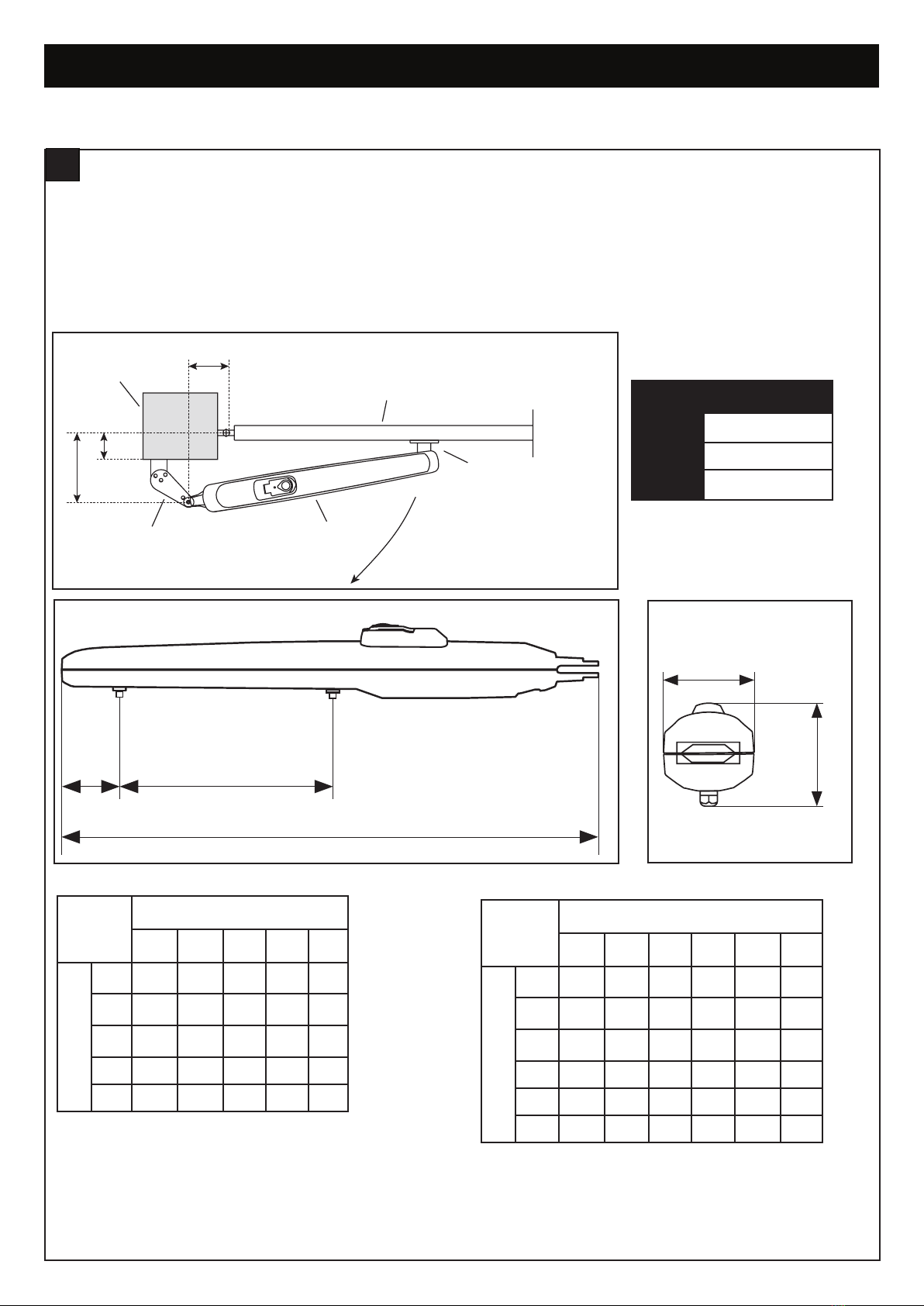
INTRODUCTION
Gate
Post Bracket
Gate Bracket
Gate Post
B
A
c
Gate Operator
Dimensions of Gate Opener
2.0m 300kg
2.5m 250kg
3.0m 200kg
mm A Table 1
100 120 140 160 180
B 100 na 120° 110° 100° 95°
120 120° 110° 100° 95° 90°
140 110° 100° 95° 90° 80°
160 100° 95° 90° 80° 75°
180 95° 90° 80° 75° 70°
mm A Table 1
100 120 140 160 180 200
B 100 na 120° 120° 115° 110° 100°
120 120° 120° 115° 110° 100° 100°
140 120° 115° 110° 110° 100° 90°
160 115° 110° 110° 100° 90° 85°
180 110° 110° 110° 90° 85° 80°
200 100° 100° 100° 85° 80° 75°
MGLX with hardstop, using max travel 300mm. MGLX without hardstop, using max travel 350mm.
835mm
350mm
55mm Max. 350mm (w/o hardstops)
Max. 300mm with hardstops
95mm
137mm
figure 1
figure 2 figure 3
DETERMINE THE POSITION OF THE POST BRACKET
7
1. Determine the A and B dimension in base on the opening angle provided in Table 1 to confirm the position where the post bracket
will be mounted.
2. The max dimension for C, should be the B dimension minus the 60mm (refer to the tables below).
3. For optimal mechanical advantage A and B dimension shall be equal or close. Therefore limit the difference between A and B
within 40mm.
NOTE: Smaller A and B dimensions determine higher peripheral speed of the leaf. Higher differences between cause greater speed and
force variations during the gate opening and closing movement. It is always good practice use all available travel of the operator.
11
INSTALLATION
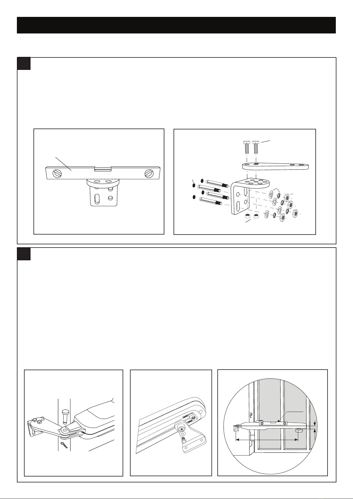
1. Using the fixed post bracket as a reference, mark and drill the holes for the post bracket.
2. Attach the post bracket to the post using appropriate fixings. Masonry fixings are supplied, if required. The correct fastening
material must be used based on existing installation (building / material substance). Please consult the gate manufacturer.
3. The slots on the post bracket allow for alignment. When the post bracket is level (see figure 1), tighten the nuts.
4. Attach the live post bracket to the fixed post bracket as per figure 2.
Level
M10x30 Screw
Non-slip nut
Drill hole
Washers
Nut
figure 1
1. Bring gate to the "closed“ position.
2. Attach the opener to the assembled post bracket using the clevis pin and secure with a hairpin clip (figure 1).
3. Assemble the assembled gate mounting bracket onto the arm using the fasteners & washers provided (figure 2).
4. Release the opener manual release with the release key. See section 11.
5. Position the gate mounting bracket as shown (figure 3).
6. Temporarily secure the gate bracket to the gate with a clamp.
7. Manually open and close the gate to the required positions. Ensure the opener does not bind. If the opening and closing positions
are OK, proceed to Step 8. If there is an issue with the desired opening position, change the gate bracket position or check if the
A and B dimensions of the post bracket were chosen correctly.
NOTE: Be sure that during the manual movement from close to open and vice versa, there is no obstruction or impact of
the arm against the leaf or pillar.
8. Close the gate and re-engage the release mechanism.
9. Connect the gate bracket securely to the gate in the chosen position with appropriate fasteners (not provided).
1115 mm
Spirit level
43.5 mm
730 mm with hardstops
750 mm w/o hardstops
Spirit level
1115 mm
Spirit level
43.5 mm
730 mm with hardstops
750 mm w/o hardstops
Spirit level
1115 mm
Spirit level
43.5 mm
730 mm with hardstops
750 mm w/o hardstops
Spirit level
figure 1 figure 3
figure 2
GATE BRACKET INSTALLATION
9
POST BRACKET INSTALLATION
8
Level
M10x30 Screw
Non-slip nut
Drill hole
Washers
Nut
figure 2

12
INSTALLATION
HARD STOPS INSTALLATION
10
1. Release the opener manual release with the release key. See section 11.
2. Using the internal opener hardstops to adjust the gate’s travelling distance, loosen each of the adjustment screws with a 5mm Allen
key.
3. Move the gate to the desired close position and reposition the hardstop to suit and secure the hardstop with a 5mm Allen key (not
supplied).
4. Move the gate to the open position and secure the hardstop in the desired position using the Allen key. Re-engage the release
mechanism.
5. If the internal opener hardstops are not used, it is mandatory to install external hardstops in the open and close positions.
NOTE: Combination of internal and external hardstops can be used.
5 mm
figure 1
DISENGAGEMENT OF THE MANUAL RELEASE
11
1. Remove the small front plastic cover from the opener.
2. Put the key into the keyhole and turn right.
3. Pull the lever down.
NOTE: To re-engage the opener, follow the procedure in reverse.
13
INSTALLATION
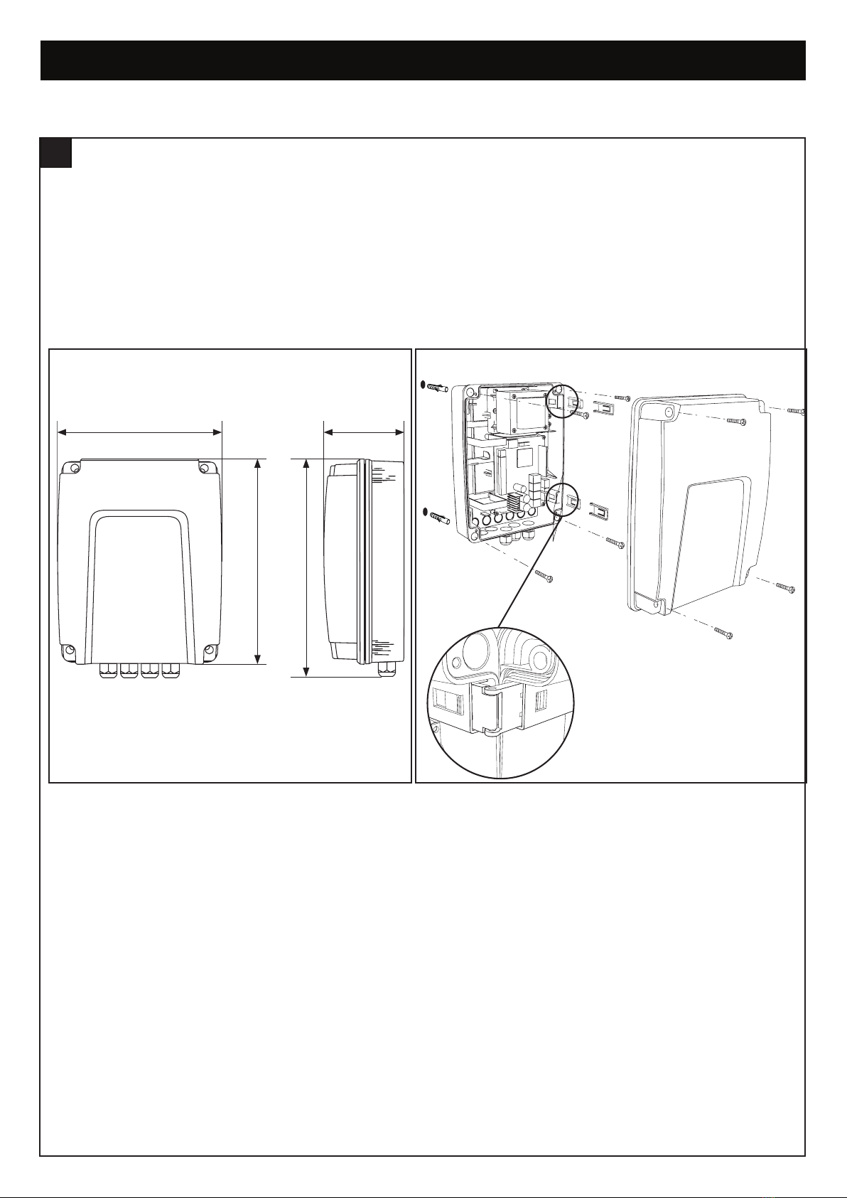
The control box must be installed at a safe location that enables the installer to have access at all times to the logic board without the
risk of the gates crushing or trapping.
It is advised that you must have full view of the gates when programming the logic board.
Install the control box in an appropriate and accessible position. The installation has to be done in accordance with local electrical
regulation.
INSTALL THE CONTROL BOX
12
8 8
225 mm 110 mm
280 mm
310 mm
Ø 6 mm drilling holes
8 8
225 mm 110 mm
280 mm
310 mm
Ø 6 mm drilling holes
figure 1 figure 2

14
WIRING
ELECTRICAL SAFETY
13
To reduce the risk of SEVERE INJURY or DEATH:
• BEFORE installing the power wiring or control stations be sure to follow all specifications and warnings. Failure to do so
may result in SEVERE INJURY to persons and/or damage to the opener.
• ALL electrical connections MUST be made by a licensed electrician.
• DO NOT install any wiring or attempt to run the opener without consulting the wiring diagram.
• ALL power wiring should be on a dedicated circuit and well protected.
• ALL power and control wiring MUST be run in separate conduit.
• Disconnect power at the fuse box BEFORE proceeding.
• ANY maintenance to the opener or in the area near the opener MUST NOT be performed until disconnecting the electrical
power (AC and battery). Upon completion of maintenance the area MUST be cleared and secured, at that time the
unit may be returned to service.
Motor1 Connection
NOTE: The opener wired to the MOTOR 1 terminal will always open first and close last.
1. Feed the motor1 cable through the selected cable gland.
2. Connect motor cables to the MOTOR1 terminals as follows: red cable to RED terminal, green cable to GRN terminal , white cable
to WHT terminal on control board.
Motor 2 Connection
NOTE: The opener wired to the MOTOR 2 terminal will always open last and close first.
1. Feed the motor 2 cable through the selected cable gland.
2. Connect motor cables to the MOTOR2 terminals as follows: red cable to RED terminal, green cable to GRN terminal , white cable
to WHT terminal on control board.
OPENER CONNECTION 1 AND 2
14
1. Isolate the power by turning power off at the isolation switch and/or circuit breaker.
2. Select a hole in bottom of the control box to be used for the incoming AC power.
3. Insert an IP rated gland into the bottom of the control box and tighten with nut.
4. Insert the 240V mains supply cables through the IP rated gland.
5. Connect the mains supply to the PCB.
6. Tighten the IP rated gland.
POWER WIRING
15

15
WIRING
12
10
13
55
5
5
9
10
12
10
0
0
0
0
4321
1
2
3
3 12
1
2
12
13
14
4
11
10
9
8
7
6
5
1
3
2
34 2 1
3
2
1
2 13
2 13
2
1
2
1
1
2
1
22
1
2
11
2
1
2
5
432
1
678910
2
1
11
1
2
11
1
1
IN1
IN1
IN2
IN2
IN3
IN3
WIRING DIAGRAM
16
16
WIRING
24 V BAT
POW
24 V
POWER BOARD
THE PROTECTOR SYSTEM™ (IR BEAMS) (OPTIONAL)
NOTE: Merlin strongly recommends that The Protector System™ (IR Beams) be installed on all gate openers.
Compatible Protector System™ (IR Beams) are 772ANZ and GPS15 Monitored Safety Beams.
The Protector System™ (IR Beams) can be configured to function differently when connected to IR1, IR2 or IR3
inputs.
1. Connect the Protector System™ (IR Beams) to IR1/GND or IR2/GND and or IR3/GND.
2. The IR Beams can be configured to monitor in the open or close direction or both (see section 22 IR Behaviour).
3. The IR Beams will automatically learn to the opener after they have been connected and are default to monitor the close direction.
4. If you need to remove the IRs, you will need to unlearn them from the opener. This is done by switching off the mains power off
and on again twice.
INSTALL ENTRAPMENT PROTECTION DEVICES
17
EDGE SENSOR
The Edge sensor can only be connected to the Edge inputs.
1. Remove the 8.2k resistor from the Edge inputs.
2. Connect the 8.2k compatible edge sensor to the Edge inputs.
EDGE
SE SE
IR SENSOR
GND IR3 IR2 IR1
COMMAND
GND IN3 IN2 IN1
FLA E-LK SPEC
EDGE
SE SE
IR SENSOR
GND IR3 IR2 IR1
COMMAND
GND IN3 IN2 IN1
FLA E-LK SPEC
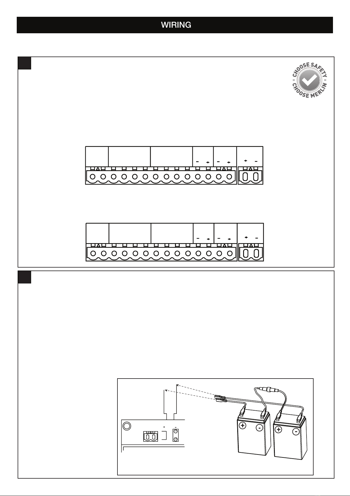
BATTERY BACKUP (OPTIONAL)
18
The batteries are charged in the circuit by the integrated transformer. Recommended items for a battery backup application (separate
accessory purchase) 2 x 12V 2.2Ah SLA batteries (model MGBBU).
1. Disconnect AC power to the opener.
2. Insert the battery power wires through the same hole as the AC power wires.
3. Connect the battery cable to the BATTERY terminals on the power board.
4. Place the batteries inside the opener.
5. Connect a jumper with an in-line fuse (10A) between the positive (+) terminal on one battery and the negative (-) terminal on the
other battery.
6. Connect the positive battery cable wire to the positive (+) terminal on the PCB.
7. Connect the negative battery cable wires to the negative (-) terminal on the PCB.
8. Reconnect AC power to the opener.
9. Place cover on the opener.
17
PROGRAMMING
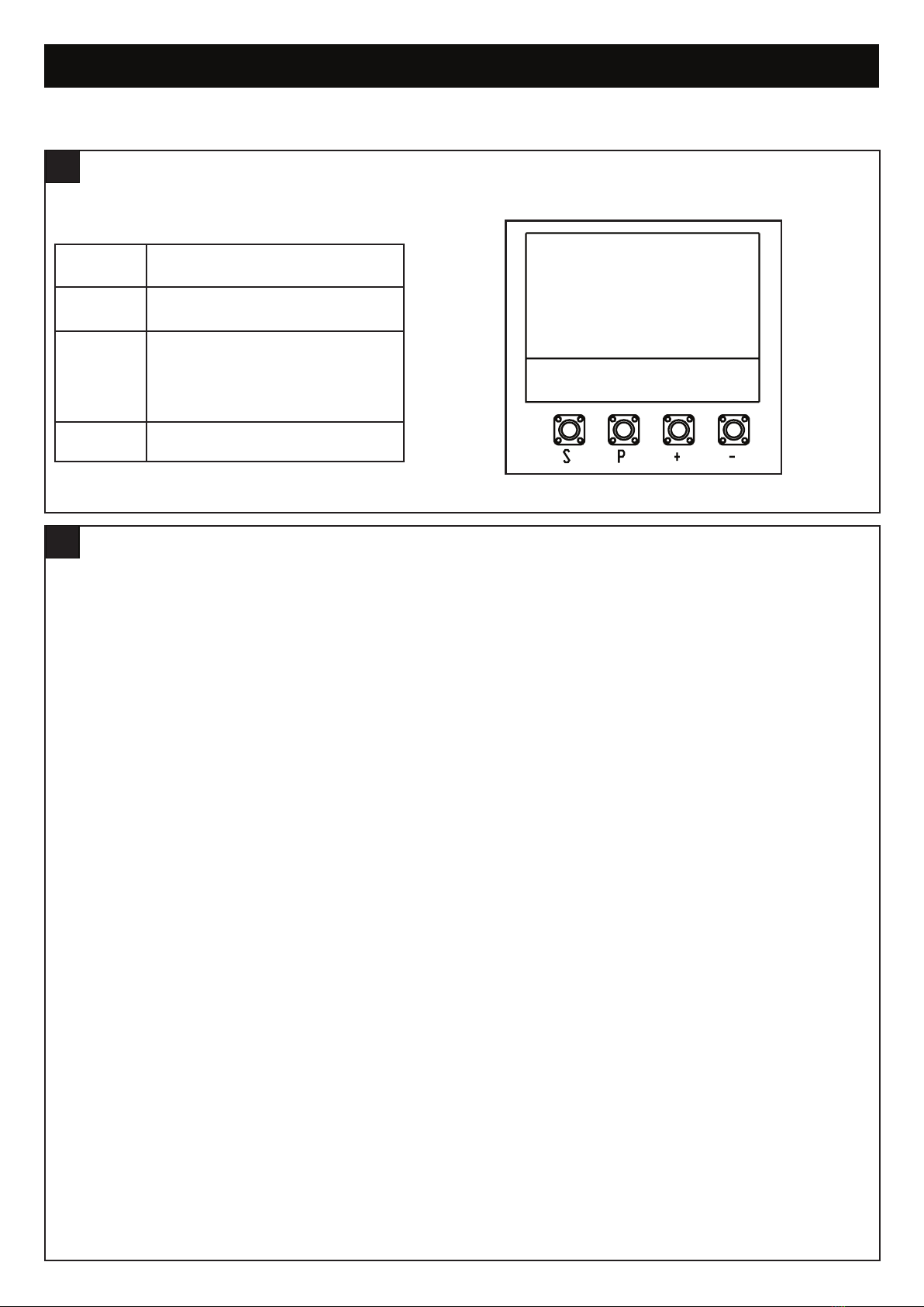
Programming buttons function (4 buttons):
LCD SCREEN MENU
19
Button Function
SProgram / delete remote controls and
specific functions
P
Enter programming mode, select
function and save.
NOTE long press of P button will save
the setting and exit out to the menu
screen.
+/- Navigate through the menu and change
the value on display
The programming of the boards is divided in two steps:
1. Basic - including Initial Setup
2. Advanced - Password Protected Settings
Initial Set-up includes:
• Selection of motor type
• Motor direction
• Limits
• Forces.
After the Initial Set-up is complete, the opener will work as per default Basic Settings.
Initial Set-up is mandatory, if they are not completed, the opener will not work.
Initial Set-up is required before any further changes to Basic or Advanced settings can be made
OVERVIEW
20

18
PROGRAMMING
OVERVIEW
20
Legend Function Section
Application Opener Motor Type 21
Direction Motor 1 Direction Motor 1 21
Direction Motor 2 Direction Motor 2 21
Limit & Force Learn Learning 22
Remote Control Behaviour Adjust the behaviour of remote controls 23
IR1-Behaviour Adjust the behaviour of Protector System Safety IR Beams in input IR 1 23
IR2-Behaviour Adjust the behaviour of Protector System Safety IR Beams in input IR 2 23
IR3-Behaviour Adjust the behaviour of Protector System Safety IR Beams in input IR 3 23
Input 1 Adjust the behaviour of Input 1 command 24
Input 2 Adjust the behaviour of Input 2 command 24
Input 3 Adjust the behaviour of Input 3 command 24
Pedestrian Setup pedestrian opening mode 25
Delay Motor 2-Open Adjust timing delay of motor 2 in open direction 26
Delay Motor 1-Close Adjust timing delay of motor 1 in close direction 27
Timer-To-Close Setup timer-to-close feature 28
Reversal Time Reversal time after obstruction has been detected 29
E-Lock E-Lock 30
Ram-Blow Setup additional electronic lock (E-Lock) or Mag-Lock options 31
Flashing Light Setup flashing light accessory 32
Pre Flashing Adjust pre flashing of flashing light accessory 33
Special Contact Relay Adjust how the special contact input will behave 34
Soft & Hard Start Setting Disable or enable the soft & hard starts 35
Maintenance Counter Setup maintenance counter for service alerts 36
The above completes the Basic Setting requirements
Password Setup, enter and change password in order to enter into the Advance settings 37
Force Motor 1-Open (PW) Adjust the forces of motor 1 in open direction 38
Force Motor 1-Close (PW) Adjust the forces of motor 1 in close direction 38
Force Motor 2-Open (PW) Adjust the forces of motor 1 in open direction 38
Force Motor 2-Close (PW) Adjust the forces of motor 2 in close direction 38
Speed-Motor 1 & 2 Open (PW) Adjust the speed of motor 1 and 2 in open direction 39
Speed-Motor 1 & 2 Close (PW) Adjust the speed of motor 1 and 2 in close direction 40
Soft Stop Speed (PW) Adjust the soft speed, which is the remaining speed towards the end of the travel 41
Factory Reset Reset opener 42
Finish and Exit Complete and exit screen N/A

19
PROGRAMMING
INITIAL SETUP
21
SP
+-
LINEAR ARM
SINGLE
SP
+-
SP
+-
MAIN MENU
DIRECTION MOTOR1
PRESS & HOLD “+”
GATE OPENING?
YES “P”, NO “S”
SP
+-
MAIN MENU
DIRECTION MOTOR1
SP
+-
MAIN MENU
SELECT
APPLCATION
SP
+-
CYCLES: 000, 000
BEGIN SETUP
SP
+-
MAIN MENU
SELECT
APPLCATION
SP
+-
MAIN MENU
SELECT
APPLCATION
SP
+-
MAIN MENU
LIMITED & FORCE
LEARN
SP
+-
MAIN MENU
SELECT
APPLCATION
SP
+-
MAIN MENU
LIMITED & FORCE
LEARN
SP
+-
CYCLES 000,000
STANDBY
GATE CLOSED
figure 1
figure 2
figure 3
Energise the opener. Release the opener manual
release with the key, and move the gate(s) to a mid
open position. Re-engage the manual release.
The LCD screen will display the Cycle count.
1. Press and hold the “P” button for approximately 5
seconds to enter into the Main Menu. MAIN
MENU SELECT APPLICATION will be displayed
on the LCD.
2. Press the “P” button once to enter this Menu
option.
3. Use the “+” or “-” to scroll though the motor
application options. When “LINEAR ARM SINGLE
OR LINEAR ARM DUAL” is shown, press the “P”
button to select. The screen will change to show
MAIN MENU SELECT APPLICATION.
4. Press the “+” button once to scroll to the next
menu option. “MAIN MENU DIRECTION
MOTOR1” will be displayed on the LCD.
5. Press the “P” button to select. The screen will
change to show PRESS & HOLD “+” GATE
OPENING? YES “P”, NO “S”.
6. Press and hold “+”. The gate will start to move.
a) If it moves in the OPEN direction, press “P” to
confirm”. The screen will change to show MAIN
MENU DIRECTION MOTOR!
b) If the gate moves in the CLOSE direction, press
“S” to confirm. The screen will change to
EXECUTE MOTOR DIRECTION CHANGE.
Press “P” to confirm.
Once the direction has been confirmed, the
screen will change to MAIN MENU DIRECTION
MOTOR. If there is a second slide gate opener to
be setup, press the ”+” button to scroll to the
next menu option “MAIN MENU DIRECTION
MOTOR2 and follow the steps 5 and 6.
7. Press the “+” button once to scroll to the next
menu option. “MAIN MENU LIMIT&FORCE
LEARN” will be displayed on the LCD.
8. Press the “P” button to select.
The gate will start
to move.
The screen will change and
LIMIT&FORCE LEARN will flash on the screen.
9. Once complete, the gate will stop moving and the
screen will change to CYCLES: 000,000
STANDBY GATE CLOSED.
Initial setup is now complete. The opener will now
operate using default Basic Settings.
NOTE: If the LIMIT&FORCE LEARN setup needs
to be stopped, press the “S” button. The Screen
will display LIMIT&FORCE LEARN INTERRUPTED.
After 5 seconds, the screen will display
LIMIT&FORCE LEARN. Repeat step 8 to complete
basic setup.

20
BASIC SETTINGS
Within the Basic Setting, navigate through the menu screen until you find “MAIN MENU
IR1-BEHAVIOUR”.
1. Press the “P” button to enter this setting (figure 1).
2. Press the “+” or “-“ buttons to navigate through the options.
3. You can select the following options:
• IR1-CLOSE DIR
• IR1-OPEN DIR
• IR1-OPEN & CLOSE DIR
• IR1-CLOSE DIR + IMMEDIATE CLOSE
4. To confirm the setting, press the “P” button to save and return to the
main menu screen.
NOTE: The above process is the same for IR2 & IR3 Behaviour.
SP
+-
MAIN MENU
IR1-BEHAVIOUR
NOTE: If Timer To Close (TTC) is activated,
during the pause time, when released after 2
seconds it will close immediately.
figure 1
REMOTE CONTROL BEHAVIOUR
23
Within the Advance Setting, navigate through the menu screen until you find “MAIN MENU
REMOTE CONTROL BEHAVIOUR”.
1. Press the “P” button to enter this setting.
2. Press the “+” or “-“ buttons to navigate through the options.
3. You can select the following options:
• OPEN-CLOSE-OPEN
• OPEN-STOP-CLOSE-STOP
• OPEN-STOP-CLOSE-OPEN
• OPEN ONLY
4. To confirm the setting, press the “P” button to save and return to the main menu
screen.
SP
+-
MAIN MENU
REMOTE CONTROL
BEHAVIOUR
figure 1
LIMIT AND FORCE LEARNING
22
Within the Basic Setting, navigate through the menu screen
until you find “MAIN MENU LIMIT & FORCE LEARN”.
1. Press the “P” button to enter this setting (figure1).
2. The menu screen will begin flashing “LIMIT & FORCE
LEARN” while this sequence is in progress and
the
gate will start to move.
3. Three seconds after successfully completing the
“LIMIT & FORCE LEARN” setup, the display will return
to the main menu in standby mode.
Note: If the LIMIT & FORCE LEARN setup needs to be
stopped, press “S” button. The screen will display
“LIMIT & FORCE LEARN INTERRUPTED” (figure 2).
After 5 seconds, the screen will display “LIMIT & FORCE
LEARN”.
SP
+-
MAIN MENU
LIMIT & FORCE LEARN
SP
+-
LIMIT & FORCE LEARN
INTERRUPTED
SP
+-
LIMIT & FORCE LEARN
SP
+-
MAIN MENU
SELECT
APPLCATION
SP
+-
MAIN MENU
LIMITED & FORCE
LEARN
SP
+-
MAIN MENU
LIMITED & FORCE
LEARN
SP
+-
CYCLES 000,000
STANDBY
GATE CLOSED
figure 1 figure 2
figure 3
IR BEHAVIOUR
24
This manual suits for next models
4
Table of contents
Other Merlin Gate Opener manuals

Merlin
Merlin Swing L300 User manual

Merlin
Merlin Slide 600 User manual

Merlin
Merlin G930 User manual

Merlin
Merlin XLR8 MGS524 User manual

Merlin
Merlin G703 User manual

Merlin
Merlin G915D User manual

Merlin
Merlin G900 User manual

Merlin
Merlin G940 User manual

Merlin
Merlin G950 User manual

Merlin
Merlin G950 User manual

Merlin
Merlin G740A User manual

Merlin
Merlin G950 User manual

Merlin
Merlin prolift 430R User manual

Merlin
Merlin G930 User manual

Merlin
Merlin Swing A 200 User manual

Merlin
Merlin Slide 600 User manual

Merlin
Merlin WingMate 3 User manual

Merlin
Merlin MGL400-24 User manual

Merlin
Merlin G703 User manual

Merlin
Merlin Swing L 300 MGLSK User manual


