manuals.online logo
Brands
  1. Home
  2. •
  3. Brands
  4. •
  5. Merlin
  6. •
  7. Gate Opener
  8. •
  9. Merlin Swing L 300 MGLSK User manual

Merlin Swing L 300 MGLSK User manual

QUICK REFERENCE GUIDE
MGLSK / MGLDK /
MGLSK-LV / MGLDK-LV
Complete Instruction Manual for the Swing L 300 MGLSK, MGLDK, MGLSK-LV & MGLDK-LV can be accessed through these QR
Codes. NOTE: The complete Instruction Manual needs to be referred to for the complete correct installation and setup process.
MGLSK
(MAINS VOLTAGE)
MGLSK-LV
(LOW VOLTAGE)
MGLDK
(MAINS VOLTAGE)
MGLDK-LV
(LOW VOLTAGE)
SAFETY INSTRUCTIONS - WARNING!
START BY READING THESE IMPORTANT SAFETY INSTRUCTIONS
ST
Before you begin the installation (The complete Instruction Manual needs to be referred to for the complete correct installation
and setup process):
This product must be installed by a professional installer.
The installer must understand the following:
• The operation of the drive and potential hazards
• The operation of the manual emergency release mechanism
• The regular maintenance, inspection and care according to the standards
• The installer must instruct other uses on the safe operation of the gate opener
Please read the operating instructions and especially the precautions. The following symbols are placed in front of instructions to avoid
personal injury or damage to property. Read these instructions carefully.
Warning Symbols
The general warning symbol indicates a danger that can lead to injuries or death. In the text section, the general warning symbols are
used as described below.
DANGER Symbol WARNING Symbol CAUTION Symbol ATTENTION Symbol
Indicates an imminent
hazardous situation which, if not
avoided, will result in death or
serious injury.
Indicates a potentially hazardous
situation which, if not avoided,
could result in death or serious
injury.
Indicates a potentially hazardous
situation which, if not avoided,
could result in minor or
moderate injury.
Indicates practices not
related to personal injury.
Intended Use
The gate opener is exclusively designed and tested for the operation of smooth-running residential gates.
The maximum permissible gate size and the maximum weight must not be exceeded. The gate must open and close smoothly by hand.
Use the opener on gates which comply with the applicable standards and guidelines. Regional conditions of wind loads must be taken
into account when using door or gate panels. Observe the manufacturer’s specifications regarding the combination of gate and opener.
Possible hazards within the meaning of AS/NZS 60335.1 in conjunction with AS/NZS 60335.2.103 are to be avoided by designing and
installing the gate according to the relevant instructions. This gate mechanism must be installed and operated in accordance with the
appropriate safety rules.
Improper Use
The construction of the gate opener is not designed for the operation of heavy-duty gates. It is not permitted on gates that travel with
incline/decline.
Any improper use of the gate opener could increase the risk of accidents. The manufacturer assumes no liability for such usage. With
this gate opener, automated gates must comply with the current, valid local standards, guidelines and regulations, AS/NZS 60335.1 in
conjunction with AS/NZS 60335.2.103.
Only Merlin genuine and approved accessories may be connected to the gate opener. Incorrect installation and/or failure to comply with
the following instructions may result in serious personal injury or damage to property.
DANGER WARNING CAUTION ATTENTION
• Failure to comply with the following instructions may result in serious personal injury or property damage.
• Read and follow all instructions carefully (The complete Instruction Manual needs to be referred to for the complete correct
installation and setup process.)
• The gate opener is designed and tested to offer safe service, provided it is installed and operated in strict accordance with the
instructions in this quick reference guide.
SAFETY INSTRUCTIONS - WARNING!
START BY READING THESE IMPORTANT SAFETY INSTRUCTIONS
ST
2
QUICK REFERENCE GUIDE
STEPS 1-6 INSTALLATION
1. Using the fixed post bracket as a reference, mark and drill the holes
for the post bracket.
2. Attach the post bracket to the post using appropriate fixings.
Masonry fixings are supplied, if required. The correct fastening
material must be used based on existing installation (building /
material substance). Please consult the gate manufacturer.
3. The slots on the post bracket allow for alignment. When the post
bracket is level (see figure 1), tighten the nuts.
4. Attach the live post bracket to the fixed post bracket as per figure 2.
Level
M10x30 Screw
Non-slip nut
Drill hole
Washers
Nut
figure 1
POST BRACKET INSTALLATION
2
1. Bring gate to the "closed“ position.
2. Attach the opener to the assembled post bracket using the clevis pin and secure with a
hairpin clip (figure 1).
3. Assemble the assembled gate mounting bracket onto the arm using the fasteners & washers
provided (figure 2).
4. Release the opener manual release with the release key. See section 5.
5. Position the gate mounting bracket as shown (figure 3).
6. Temporarily secure the gate bracket to the gate with a clamp.
7. Manually open and close the gate to the required positions. Ensure the opener does not bind. If the
opening and closing positions are OK, proceed to Step 8. If there is an issue with the desired opening
position, change the gate bracket position or check if the A and B dimensions of the post bracket were
chosen correctly.
NOTE: Be sure that during the manual movement from close to open and vice versa, there is no
obstruction or impact of the arm against the leaf or pillar.
8. Close the gate and re-engage the release mechanism.
9. Connect the gate bracket securely to the gate in the chosen position with appropriate fasteners (not provided).
1115 mm
Spirit level
43.5 mm
730 mm with hardstops
750 mm w/o hardstops
Spirit level
1115 mm
Spirit level
43.5 mm
730 mm with hardstops
750 mm w/o hardstops
Spirit level
1115 mm
Spirit level
43.5 mm
730 mm with hardstops
750 mm w/o hardstops
Spirit level
figure 1
figure 3
figure 2
GATE BRACKET INSTALLATION
3
HARD STOPS INSTALLATION
4
1. Release the opener manual release with the release key. See section 5.
2. Using the internal opener hardstops to adjust the gate’s travelling
distance, loosen each of the adjustment screws with a 5mm Allen key.
3. Move the gate to the desired close position and reposition the hardstop
to suit and secure the hardstop with a 5mm Allen key (not supplied).
4. Move the gate to the open position and secure the hardstop in the
desired position using the Allen key. Re-engage the release mechanism.
5. If the internal opener hardstops are not used, it is mandatory to install
external hardstops in the open and close positions.
NOTE: Combination of internal and external hardstops can be used.
5 mm
figure 1
Opener MGLX
Manual
Quick
Reference
guide
Control Box
MGEB or MGEB-LV Instructions
manual 2 x Release
Keys
Fix Post
Bracket Live Post
Bracket
Hairpin
Clip Clevis
Clip
4 x M8 x 80mm
Masonry Anchors
Quick
Reference
Guide
Gate Transformer
240V -24V 120VA
MGTR3-120VA
2 x 4 Channel
Transmitters 13 mm Bolt
& Washer
Gate
Mounting
Bracket
2 x M10x30
Bolts
Manual
Quick
Reference
guide
2 x Opener MGLX
2 x Control Box
MGEB or MGEB-LV Instructions
manual 4 x Release
Keys
2 x Fix Post
Bracket 2 x Live Post
Bracket
2 x Hairpin
Clip
2 x Clevis
Clip
8x M8 x 80mm
Masonry Anchors
Quick
Reference
Guide
Gate Transformer
240V -24V 120V
A
MGTR3-120VA
2 x 4 Channel
Transmitters
2 x 13 mm Bolt
& Washer
2 x Gate
Mounting
Bracket
4 x M10x30
Bolts
1
Take out each of the items
included in the sales kit.
Note that low voltage sales
kits MGLSK-LV & MGLDK-LV
includes gate transformer
(MGTR3-120VA).
SINGLE KITS DUAL KITS
Level
M10x30 Screw
Non-slip nut
Drill hole
Washers
Nut
figure 2
3
QUICK REFERENCE GUIDE
DISENGAGEMENT OF THE MANUAL RELEASE
5
1. Remove the small front plastic cover from the opener.
2. Put the key into the keyhole and turn right.
Pull the lever down.
NOTE: To re-engage the opener, follow the procedure in reverse..
figure 1
The control box must be installed at a safe location that enables the installer to have access at all times to the logic board without the
risk of the gates crushing or trapping.
It is advised that you must have full view of the gates when programming the logic board.
Install the control box in an appropriate and accessible position. The installation has to be done in accordance with local electrical
regulation.
Motor1 Connection
NOTE: The opener wired to the MOTOR 1 terminal will always open first and close last.
1. Feed the motor1 cable through the selected cable gland.
2. Connect motor cables to the MOTOR1 terminals as follows: red cable to RED terminal, green cable to GRN terminal , white cable
to WHT terminal on control board.
Motor 2 Connection
NOTE: The opener wired to the MOTOR 2 terminal will always open last and close first.
1. Feed the motor 2 cable through the selected cable gland.
2. Connect motor cables to the MOTOR2 terminals as follows: red cable to RED terminal, green cable to GRN terminal , white cable
to WHT terminal on control board.
INSTALL THE CONTROL BOX
6
POWER WIRING
1. Isolate the power by turning power off at the isolation switch and/or circuit breaker.
2. Select a hole in bottom of the control box to be used for the incoming AC power.
3. Insert an IP rated gland into the bottom of the control box and tighten with nut.
4. Insert the 240V mains supply cables through the IP rated gland.
5. Connect the mains supply to the PCB.
6. Tighten the IP rated gland.
8 8
225 mm 110 mm
280 mm
310 mm
Ø 6 mm drilling holes
8 8
225 mm 110 mm
280 mm
310 mm
Ø 6 mm drilling holes
4 114A5579A
QUICK REFERENCE GUIDE
COMMISSIONING AND PROGRAMMING
THE PROTECTOR SYSTEM™ (IR BEAMS) (OPTIONAL)
NOTE: Merlin strongly recommends that The Protector System™ (IR Beams) be installed on all gate openers.
Compatible Protector System™ (IR Beams) are 772ANZ and GPS15 Monitored Safety Beams.
The Protector System™ (IR Beams) can be configured to function differently when connected to IR1, IR2 or IR3 inputs.
1. Connect the Protector System™ (IR Beams) to IR1/GND or IR2/GND and or IR3/GND.
2. The IR Beams can be configured to monitor in the open or close direction or both (see section 23 IR Behaviour).
3. The IR Beams will automatically learn to the opener after they have been connected and are default to monitor the close direction.
4. If you need to remove the IRs, you will need to unlearn them from the opener. This is done by switching off the mains power off and
on again twice.
INSTALL ENTRAPMENT DEVICES
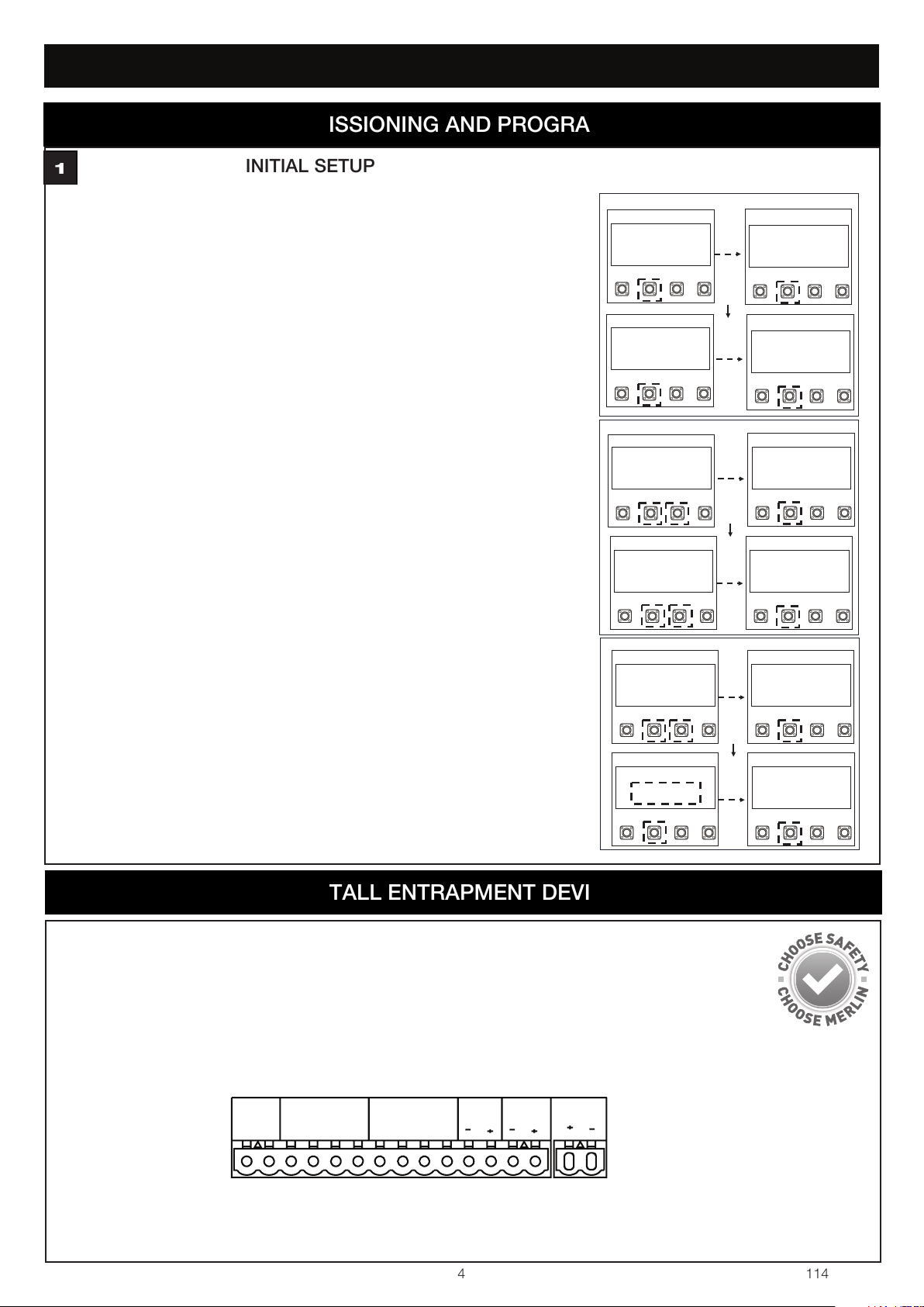
PROGRAMMING - INITIAL SETUP
1
Energise the opener. Release the opener manual release with the key, and move the
gate(s) to a mid open position. Re-engage the manual release.
The LCD screen will display the Cycle count.
1. Press and hold the “P” button for approximately 5 seconds to enter into the Main
Menu. MAIN MENU SELECT APPLICATION will be displayed on the LCD.
2. Press the “P” button once to enter this Menu option.
3. Use the “+” or “-” to scroll though the motor application options. When “LINEAR
ARM SINGLE OR LINEAR ARM DUAL” is shown, press the “P” button to select.
The screen will change to show MAIN MENU SELECT APPLICATION.
4. Press the “+” button once to scroll to the next menu option. “MAIN MENU
DIRECTION MOTOR1” will be displayed on the LCD.
5. Press the “P” button to select. The screen will change to show PRESS & HOLD “+”
GATE OPENING? YES “P”, NO “S”.
6. Press and hold “+”. The gate will start to move.
a) If it moves in the OPEN direction, press “P” to confirm”. The screen will change
to show MAIN MENU DIRECTION MOTOR1
b) If the gate moves in the CLOSE direction, press “S” to confirm. The screen will
change to
EXECUTE MOTOR DIRECTION CHANGE.
Press “P” to confirm.
Once the direction has been confirmed, the screen will change to MAIN MENU
DIRECTION MOTOR. If there is a second slide gate opener to be setup, press the
”+” button to scroll to the next menu option “MAIN MENU DIRECTION MOTOR2
and follow the steps 5 and 6.
7. Press the “+” button once to scroll to the next menu option. “MAIN MENU
LIMIT&FORCE LEARN” will be displayed on the LCD.
8. Press the “P” button to select.
The gate will start to move.
The screen will change
and LIMIT&FORCE LEARN will flash on the screen.
9. Once complete, the gate will stop moving and the screen will change to CYCLES:
000,000 STANDBY GATE CLOSED.
Initial setup is now complete. The opener will now operate using default Basic Settings.
NOTE: If the LIMIT&FORCE LEARN setup needs to be stopped, press the “S”
button. The Screen will display LIMIT&FORCE LEARN INTERRUPTED. After 5
seconds, the screen will display LIMIT&FORCE LEARN. Repeat step 8 to
complete basic setup.
EDGE
SE SE
IR SENSOR
GND IR3 IR2 IR1
COMMAND
GND IN3 IN2 IN1
FLA E-LK SPEC
SP
+-
LINEAR ARM
SINGLE
SP
+-
SP
+-
MAIN MENU
DIRECTION MOTOR1
PRESS & HOLD “+”
GATE OPENING?
YES “P”, NO “S”
SP
+-
MAIN MENU
DIRECTION MOTOR1
SP
+-
MAIN MENU
SELECT
APPLCATION
SP
+-
CYCLES: 000, 000
BEGIN SETUP
SP
+-
MAIN MENU
SELECT
APPLCATION
SP
+-
MAIN MENU
SELECT
APPLCATION
SP
+-
MAIN MENU
LIMITED & FORCE
LEARN
SP
+-
MAIN MENU
SELECT
APPLCATION
SP
+-
MAIN MENU
LIMITED & FORCE
LEARN
SP
+-
CYCLES 000,000
STANDBY
GATE CLOSED
figure 1
figure 2
figure 3
EDGE SENSOR
The Edge sensor can only be connected to the Edge inputs.
1. Remove the 8.2k resistor from the Edge inputs.
2. Connect the 8.2k compatible edge sensor to the Edge inputs.

This manual suits for next models

3

Other Merlin Gate Opener manuals

Merlin G950 User manual

Merlin

Merlin G950 User manual

Merlin G930 User manual

Merlin

Merlin G930 User manual

Merlin G703 User manual

Merlin

Merlin G703 User manual

Merlin Swing L 300 MGL Series User manual

Merlin

Merlin Swing L 300 MGL Series User manual

Merlin prolift 430R User manual

Merlin

Merlin prolift 430R User manual

Merlin Swing L300 User manual

Merlin

Merlin Swing L300 User manual

Merlin Swing A 200 User manual

Merlin

Merlin Swing A 200 User manual

Merlin G950 User manual

Merlin

Merlin G950 User manual

Merlin G740A User manual

Merlin

Merlin G740A User manual

Merlin G930 User manual

Merlin

Merlin G930 User manual

Merlin G715D User manual

Merlin

Merlin G715D User manual

Merlin G815D User manual

Merlin

Merlin G815D User manual

Merlin XLR8 MGS524 User manual

Merlin

Merlin XLR8 MGS524 User manual

Merlin G900 User manual

Merlin

Merlin G900 User manual

Merlin Swing A 200 User manual

Merlin

Merlin Swing A 200 User manual

Merlin Slide 600 User manual

Merlin

Merlin Slide 600 User manual

Merlin MGL400-24 User manual

Merlin

Merlin MGL400-24 User manual

Merlin G940 User manual

Merlin

Merlin G940 User manual

Merlin WingMate 3 User manual

Merlin

Merlin WingMate 3 User manual

Merlin G915D User manual

Merlin

Merlin G915D User manual

Merlin Slide 600 User manual

Merlin

Merlin Slide 600 User manual

Merlin G950 User manual

Merlin

Merlin G950 User manual

Merlin G703 User manual

Merlin

Merlin G703 User manual

Popular Gate Opener manuals by other brands

fadini FIBO 300 instruction manual

fadini

fadini FIBO 300 instruction manual

Mighty Mule 200 E-Z GATE OPENER UL325 SERIES installation manual

Mighty Mule

Mighty Mule 200 E-Z GATE OPENER UL325 SERIES installation manual

Real Carriage Door & Sliding Hardware Franklin Autoswing installation manual

Real Carriage Door & Sliding Hardware

Real Carriage Door & Sliding Hardware Franklin Autoswing installation manual

Chamberlain SGO500 instructions

Chamberlain

Chamberlain SGO500 instructions

TOPMAQ MK1101 user manual

TOPMAQ

TOPMAQ MK1101 user manual

CAME BY-3500T installation manual

CAME

CAME BY-3500T installation manual

V2 BINGO400 user manual

V2

V2 BINGO400 user manual

Nice Thor1500Kit Instructions and warnings for installation and use

Nice

Nice Thor1500Kit Instructions and warnings for installation and use

Schartec P190 Control Box user manual

Schartec

Schartec P190 Control Box user manual

GFA 10003805 00012 installation instructions

GFA

GFA 10003805 00012 installation instructions

Proteco Advantage Installation and user manual

Proteco

Proteco Advantage Installation and user manual

GFA ELEKTROMAT SE 14.21-25,40 ER installation instructions

GFA

GFA ELEKTROMAT SE 14.21-25,40 ER installation instructions

HySecurity SlideDriver II installation manual

HySecurity

HySecurity SlideDriver II installation manual

US Automatic SENTRY 300 S Installation & owner's manual

US Automatic

US Automatic SENTRY 300 S Installation & owner's manual

Cardin Elettronica 800/HL2524ESB instruction manual

Cardin Elettronica

Cardin Elettronica 800/HL2524ESB instruction manual

SELTEX V350 user manual

SELTEX

SELTEX V350 user manual

FAAC 402 manual

FAAC

FAAC 402 manual

tau DAN Automatik MF30 installation manual

tau

tau DAN Automatik MF30 installation manual

manuals.online logo
manuals.online logoBrands
  • About & Mission
  • Contact us
  • Privacy Policy
  • Terms and Conditions

Copyright 2025 Manuals.Online. All Rights Reserved.