TMT Automation PAPILLON 250 User manual

PAPILLON 250
ARTICULATED ARM OPENERS
24V DC GEAR MOTOR
USER MANUAL
Transformer

INDEX
1.1 GENERAL PRECAUTION
1.2 INSTALLATION
A. STANDARD INSTALLATION
B. DIMENSION CHART
C. Components of installation
D. Installation of articulated arm opener
E. Wire Connection
F. Emergency Release
G. Photocell Installation
H. Green Box Installation
I. Power Supply Connections
2. CB19 Control Box
2.1 LED Indication
2.2 Transmitter Memorizing and Erasing Process
2.3 System Learning Process
2.4 Gate Operation
2.5 Gate-Moving Logic
2.6 Checking the Gate Mevements
3. Function Setting
3.1 Function of the LED Display
3.2 Photocell Adjustment
4. Trouble Shooting
5. Technical Features
A. Dimension
B. Technical Feature:
6. Maintenance
1
2
2
2
3
3
4
5
5
6
6
7
10
10
10
11
11
11
11
11
12
13
13
13
14
14

ARTICULATED ARM OPENERS USER MANUAL
1.1 GENERAL PRECAUTION:
1
WARNING :
This user manual is only for qualified technicians who is specialized in installations and automations.
(1) All installations, electrical connections, adjustments and testing must be performed only after
reading and understanding of all instructions carefully.
(2) Before carrying out any installation or maintenance operation, disconnect the electrical power
supply by turning off the magneto thermic switch connected upstream and apply the hazard area
notice required by applicable regulations.
(3) Make sure the existing structure is up to standard in terms of strength and stability.
(4) When necessary, connect the motorized gate to reliable earth system during electricity connection phase.
(5) Installation requires qualified personnel with mechanical and electrical skills.
(6) Keep the automatic controls (remote, push bottom, key selectors…etc) being placed properly
and away from children.
(7) For replace or repair of the motorized system, only original parts must be applied. Any damage
caused by inadequate parts and methods will not be claimed to motor manufacturer.
(8) Never operate the drive if you have any suspect with what it might be faulty or damage to the system.
(9) The motors are exclusively designed for the gate opening and closing application, any other
usage is deemed inappropriate. The manufacture should not be liable for any damage resulting
from the improper use. Improper usage should void all warranty, and the user accepts sole
responsibility for any risks thereby may accrue.
(10) The system may only be operated in proper working order. Always follow the standard procedures
by following the instructions in this installation and operating manual.
(11) Only command the remote when you have a full view of the gate.
Please keep this installation manual for future reference.

ASTANDARD INSTALLATION
BDIMENSION CHART
ARTICULATED ARM OPENERS USER MANUAL
2
1.2 INSTALLATION
2x1.5 mm2
4x0.5 mm2
TX - 4x0.5 mm2
RX - 4x0.5 mm2
2x1.5 mm2
2x1.5 mm2
Please comply with the measures shown on the chart for proper installation. If necessary,
please adjust the gate structure to the best operation.
Before starting the installation, please make sure that the gate moves freely and that :
1) Hinges are properly positioned and greased.
2) No any obstacle in the moving area.
3) No frictions between two gate leafs or and on the ground while moving.
4) To leave enough space when the gate is opening.
a. Distance between the bolt and horizontal wall surface.
b. Distance from the bolt perpendicular to the surface of articulated arm opener.
c. Distance between the position of arm fixation and the bolt.
d. Installation angle from full closed and full opened position.
44
2
33
1
5
1. 24V DC blinker with integrated antenna
2. Push Button
3. Photocells
4. 24V DC articulated arm opener
5. TM3 Transmitter
A(mm)
50
50
50
100
100
100
150
150
150
B(mm)
50
100
150
50
100
150
50
100
150
C(mm)
450~650
380~640
360~620
390~600
370~590
360~580
450~600
510~590
500~580
D
90o
90o
90o
90o
90o
90o
100o
100o
100o
A
D
C
B

CCOMPONENTS OF INSTALLATION
DINSTALLATION OF ARTICULATED ARM OPENER
ARTICULATED ARM OPENERS USER MANUAL 3
1. Refer to the Dimension Chart to choose the correct dimensions of the motors and
position to be installed.
2. Check if the mounting surface of the brackets to be installed is smooth, vertical and rigid.
3. Arrange the cables for power supply cable of the motors.
4. Motor installation and setting for mechanical stopper in opened and closed position.
1
2
3
4
5
6
7
8
9
10
11
12
13
Straight arm
Curved arm
U-shaped fixing plate
Mechanical stopper
Front-end fixing bracket
Screw
Nut Ø10
Screw
Gasket
Screw
Spring washer
Nut Ø8
Cable gland
1 pce
1 pce
1 pce
2 pcs
1 pce
4 pcs
2 pcs
2 pcs
2 pcs
2 pcs
4 pcs
4 pcs
1 pce
2
3 4 5
6
7
8
13 12 11 10 9
1
2) Place the gate in the full closed position and
fix the U-shaped fixing plate on the wall.
1) Remove the upper cover and mechanical
stoppers on the bottom of motor.
A
D
C
B

ARTICULATED ARM OPENERS USER MANUAL
4
4) After positioning the front of curved arm on the bottom of motor,
release the motor and position the minor arm on the end of
curved arm and mounting bracket with corresponding screws
and nuts.
5) Closed position adjustment :
4.1 After the full closed position decided, fix the corresponding mechanical stopper at the position.
4.2 After the full closed position decided, make the pointer on limit switch aligned with the pointer on the curved arm.
(Red points shown on the figure below indicate the pointers)
6) Opened position adjustment :
5.1 Adjust the gate to full opened position and after the position decided, fixed with corresponding mechanical stopper.
5.2 Adjust the gate to full opened position and after the position decided, make the pointer on the electromechanical
limit switch aligned with the pointer on the curved arm. (Red points shown on the figure below indicate the pointers)
WIRE CONNECTION
EWhite (+)
Yellow (-) Motor
Red (5V)
White (Signal)
Black (GND)
Blue (Left-side electromechanical limit switch)
Green (Right-side electromechanical limit switch)
1
5
2
4
13
7
3
8
12
3) Install the motor on the U-shaped fixing
plate with corresponding screws and nuts.
White
+Yellow
-
Red
5V Green
Signal Black
(GND) Blue
Limit 1 Gray
Limit 2
12
9
10

ARTICULATED ARM OPENERS USER MANUAL 5
EMERGENCY RELEASE
F
1) Insert the release key to the release slot
2) Turn the release key anti-clockwise
3) Pull out the release bar
4) Turn the release key clockwise to fix the release bar, the release bar has to be in pulled out position when turning
the release key clockwise
The safety photocells are security devices for control automatic gates. Consist of one transmitter and one receiver
based in waterproof covers; it is triggered while breaking the path of the beams.
INSTALLATION:
Wire Connection of Photocells
TX: Connect terminals 1 and 2 on the transmitter with the terminals GND and PhVcc on the CB19 PCB.
RX: Connect terminals 1,2 and 4 on the receiver with the terminals GND, PhVcc, and Ph1/Ph2 on the CB19 PCB.
And use an extra wire to connect terminals 2 and 5 on the receiver as a bridge.
Detection Method
Sensing Range
Input Voltage
Response Time
Emitting Element
Operation Indicator
Dimensions
Output Method
Current Consumption Max
Water Proof
Through Beam
25M
AC/DC 12~24V
100MS
IR LED
Red LED(RX): ON(When Beam is Broken), Green(TX):ON
96*45*43mm
Relay Output
TX: 35MA/Rx: 38MA (When beam aligned properly);
TX: 35MA/ Rx: 20MA (When beam is broken)
IP54
RX
RX
Lens
Beam Alignmnet
Indicator
Power Led
Indicator
Terminal Block
Power
Terminal Block
COM
N.C.
N.O.
GND
DC (12~24V)
GND
DC (12~24V)
TX
TX
SPECIFICATION:
Figure 1(6)
Figure 1(5)
1 2 3 4 5
1 2 3 4 5 1 2
1 2
PHOTOCELL INSTALLATION
G

ARTICULATED ARM OPENERS USER MANUAL
6
Figure 1(7)
Please kindly notice that the operation of power connection should be carried out by a qualified electrician with
following steps:
1). Make sure the gearmotor is not connected to the power supply before the installation is done.
2). Make sure all the wires are firmly connected.
3). Supply the gearmotor with the power.
OFF ON
Green Box
5+
Cable AC out
AC in
Green Box is for purpose when gate opener is in standby mode to allow it enter the power saving mode.
Installation manner:
AC IN: connect the electricity
AC OUT: connect the power of gate opener, and connect the transformer
5V CABLE: connect 3 pins white socket of control board
Please make sure the switch of Green Box is off before proceeding the system learning and installation of device.
Wait for the system learning and installation of device to be completed, power on the Green Box
Gate opener will enter power saving mode without receiving any instruction in 1 min, and red LED light on Green Box
will be activated. Gate opener start the operation, red LED light and power saving mode will turn off.
CAUTION:
In case of loop or installation of photocell which need power consumption anytime, please do not install Green Box.
GREEN BOX INSTALLATION
H
POWER SUPPLY CONNECTIONS
I

ARTICULATED ARM OPENERS USER MANUAL 7
2. CB19 CONTROL BOX
1. Decide the installation position of control box first, it is suggested to be installed near the gate and should
be protected from possible damage. Be aware of the motor cable length before deciding the installation position.
2. Remove the cover by unscrewing the four screws on the cover. See Figure 1(1).
3. Use a screwdriver to puncture the holes beneath the bottom of the control box. See Figure 1(2).
4. Secure it on the wall.
5. Motor Wiring Connection:
1).Motor Power only (M+, M-) See Figure 1(2)
Gate openers: Refer to Figure 1(4) and connect the wires separately to the terminals on the PCB.
Motor 1: Connect the motor wire (White +) to the terminals M1+, and (Yellow -) to the M1-.
Motor 2: Connect the motor wire (White +) to the terminals M2+, and (Yellow -) to the M2-.
2) Motor with Limit Switch (M+, M-, Limit1, Limit2, GND) See Figure 1(3)
Gate openers: Refer to Figure 1(4) and connect the wires separately to the terminals on the PCB.
Motor 1: Connect the motor wire (White +) to the terminals M1+, and (Yellow -) to the M1-.
Connect the Limit switch wires red, white, and black to the terminal Limit1, Limit2, and GND.
Motor 2: Connect the motor wire (White +) to the terminals M2+, and (Yellow -) to the M2-.
Connect the Limit switch wires red, white, and black to the terminal Limit3, Limit4, and GND.
3) Motor with Hall sensor (M+, M-, 5V, Signal, GND) See Figure 1(4)
Gate openers: Refer to Figure 1(4) and connect the wires separately to the terminals on the PCB.
Motor 1: Connect the motor wire (White +) to the terminals M1+, and (Yellow -) to the M1-.
Connect the Limit switch wires red, green, and black to the terminal 5V, S1, and GND.
Motor 2: Connect the motor wire (White +) to the terminals M2+, and (Yellow -) to the M2-.
Connect the Limit switch wires red, green, and black to the terminal 5V, S2, and GND.
6. Accessories Wiring Connection
Prepare all the wires of the accessories beforehand and connect the wires to the gear motors and accessories on
the PCB as shown in Figure 1(4). All of the wiring connections of the accessories are not requested to
distinguish the positive (+) and the negative (-) polarity.
1). Flashing Light: Connect the two wires from the flashing light to the terminal L+ and L- on the PCB.
2). Electric Latch: Connect the two wires from the electric latch to the terminal Lo + and Lo- on the PCB.
3). Photocells: See Figure 1(4)
(A) If installed one set Photocell to Ph1, please choice 1 in FC.
(B) If installed one set Photocell to Ph2,.please choice 1 in FD.
(C) If installed two sets Photocell, please choice 1 for FC and FD.
(D) If No Photocell has been installed,please choice 0 in FC and FD.

ARTICULATED ARM OPENERS USER MANUAL
8
Figure 1(1)
Flashing
Light
Latch Key
Selector
Push
Button
Transformer
Antenna
TX1
TX2
RX1 RX2 Green Box
M2-M1-
Lat-
Lit- Lmt4Lmt3
Lmt2
Lit+ SKey
S1
M2+
M1+Lat+ Ph2Ph1 PhVcc PhVcc
S25V
ANT
GND
DKey GND
GND GND GND
Lmt1 GND
CB19-PCB1
40121-377-A1
+ -
T4
SW3
J1
Q17
R113
R112
R111
R110
R108
R107
R106
R105
R104
R103
R102
J5
SW1
RF1
MOV1
K5
K3
K2K1
J4 J3
J7
J2
F1
DB1
J8
SW4
SW5
NC NO
CO
+-
NC NO
CO
+-- +
CO
NONC
- +
CO
NONC
NC NO
CO
+-
-
+
1 2 3 4 5 6 7 8
9 10 11 12 13 14 15 16 17 18 19 20 21 22 23 24 25 26
LED2 LED3
LED4
LED Display
LED1 RF Learning
LED2 Photocell 2
LED4 Photocell 1
LED3 Push botton or Key selector
LED1
UP
RF-LEARN
SET
DOWN

ARTICULATED ARM OPENERS USER MANUAL
9
Figure 1(2)
Motor Only
Figure 1(3)
Motor with Limit switch
Figure 1(4)
Motor with Hall sensor
Motor1
Power
Motor2
Power
Antenna
M2-M1-
Lat-
Lit- Lmt4Lmt3
Lmt2
Lit+ SKey
S1
M2+
M1+Lat+ Ph2Ph1 PhVcc PhVcc
S25V
ANT
GND
DKey GND
GND GND GND
Lmt1 GND
CB19-PCB1
40121-377-A1
Q17
J5
RF1
K5
K3
K2K1
J4 J3
J7
J8
NC NO
CO
+-
NC NO
CO
+-- +
CO
NONC
- +
CO
NONC
NC NO
CO
+-
1 2 3 4 5 6 7 8
9 10 11 12 13 14 15 16 17 18 19 20 21 22 23 24 25 26
LED2 LED3
LED4
Motor1
Power
Motor2
Power
Motor1
limit switch
Motor2
limit switch
Antenna
M2-M1-
Lat-
Lit- Lmt4Lmt3
Lmt2
Lit+ SKey
S1
M2+
M1+Lat+ Ph2Ph1 PhVcc PhVcc
S25V
ANT
GND
DKey GND
GND GND GND
Lmt1 GND
CB19-PCB1
40121-377-A1
+ -
T4
SW3
UP
J1
Q17
R113
R112
R111
R110
R108
R107
R106
R105
R104
R103
R102
J5
SW1
RF-LEARN
RF1
MOV1
K5
K3
K2K1
J4 J3
J7
J2
F1
DB1
J8
SW4
SET
SW5
DOWN
NC NO
CO
+-
NC NO
CO
+-- +
CO
NONC
- +
CO
NONC
NC NO
CO
+-
-
+
1 2 3 4 5 6 7 8
9 10 11 12 13 14 15 16 17 18 19 20 21 22 23 24 25 26
LED2 LED3
LED4
Motor1
Power
Motor2
Power
Motor1
Hall sensor
Motor2
Hall sensor
Transformer
Antenna
M2-M1-
Lat-
Lit- Lmt4Lmt3
Lmt2
Lit+ SKey
S1
M2+
M1+Lat+ Ph2Ph1 PhVcc PhVcc
S25V
ANT
GND
DKey GND
GND GND GND
Lmt1 GND
CB19-PCB1
40121-377-A1
+ -
T4
SW3
UP
J1
Q17
R113
R112
R111
R110
R108
R107
R106
R105
R104
R103
R102
J5
SW1
RF-LEARN
RF1
MOV1
K5
K3
K2K1
J4 J3
J7
J2
F1
DB1
J8
SW4
SET
SW5
DOWN
NC NO
CO
+-
NC NO
CO
+-- +
CO
NONC
- +
CO
NONC
NC NO
CO
+-
-
+
1 2 3 4 5 6 7 8
9 10 11 12 13 14 15 16 17 18 19 20 21 22 23 24 25 26
LED2 LED3
LED4

ARTICULATED ARM OPENERS USER MANUAL 10
2.3 SYSTEM LEARNING PROCESS
Step1: Connect the master motor wires to M1 terminals and the slave motor wires to M2 terminals correctly. If only
one gate is installed, the motor wires have to be connected to M1 terminals.
Step2: Set the function F2-1 for double gate learn; or set the function F2-2 for sigle gate learning.
Step3: Press and hold the “UP+SET+DOWN” button on the PCB for 3 seconds. After LED1 blinks once per second,
press the button on the transmitter to choose dual-gate(A button) or single-gate(B button) system learning.
In system learning mode, the gates will proceed with the following procedures.
Step4: When changing F2 setting, it is required to do the system learning process again.
(A) Dual-Gate Mode: Slave Gate closes→Master Gate closes→Master Gate opens→Slave Gate opens→Slave
Gate closes→Master Gate closes.
(B) Single-Gate Mode: Master Gate closes→Master Gate opens→Master Gate closes.
The completion of system learning:
(A) For Dual-Gate installation: The system learning is completed when LED1 quickly blinks twice per second.
(B) For Single-Gate installation: The system learning is completed when LED1 quickly blinks once per second.
Notes:
(A) System learning fails and needs to be learned again when an unpredictable interruption occurs.
(B) Once the system learning is completed, there is no need to proceed with the learning process again when
there isa power failure.
(C) The slave gate opens 3 seconds after the master gate opens and the master gate closes 3 seconds after the
slave gate closes.
(D) While using limit switch mode, please make sure the motor hit limit switch when it’s in deceleration speed.
2.2 TRANSMITTER MEMORIZING AND ERASING PROCESS
(A) Transmitter Memorizing: Press and hold the “RF-LEARN” button on the PCB for 1 second and then the blue LED
indicator on the RF board will be “ON”. Press A button for dual-gate installation ; press B button for single-gate
installation on the transmitter within 5 seconds. The transmitter learning is completed
when the blue indicator is “OFF”.
(B) Transmitter Memory Erasing: Press and hold the “RF-LEARN” button on the PCB for 10 seconds until blue LED off.
(C) One radio receiver can be memorized with 200pcs of transmitters.
LED1 System Learning: blue LED1 in receiver board blinks three times when learning is completed.
LED2 RF : If the switch of the transmitter, key selector, or the push button is activated, LED2 will be on.
LED3 Photocells 1 : LED3 will be on when the first pair of the photocells are activated.
LED4 Photocells 2 : LED4 will be on when the second pair of the photocells are activated.
Antenna
M2-M1-
Lat-
Lit- Lmt4Lmt3
Lmt2
Lit+ SKey
S1
M2+
M1+Lat+ Ph2Ph1 PhVcc PhVcc
S25V
ANT
GND
DKey GND
GND GND GND
Lmt1 GND
CB19-PCB1
40121-377-A1
T4
SW3
UP
Q17
J5
SW1
RF-LEARN
RF1
K5
K3
K2K1
J4 J3
J7
F1
DB1
J8
SW4
SET
SW5
DOWN
NC NO
CO
+-
NC NO
CO
+-- +
CO
NONC
- +
CO
NONC
NC NO
CO
+-
-
+
1 2 3 4 5 6 7 8
9 10 11 12 13 14 15 16 17 18 19 20 21 22 23 24 25 26
LED2 LED3
LED4
2.1 LED INDICATION

ARTICULATED ARM OPENERS USER MANUAL
11
2.4 GATE OPERATION
Press the button “A” on the transmitter for dual-gate operation.
Press the button “B” on the transmitter for single-gate
operation in either single-gate or dual-gate installation.
2.5 GATE-MOVING LOGIC
(A) In gate-opening phase: The gates stop if the transmitter/push button/key selector is activated, and close when
the transmitter/push button/key selector is reactivated.
(B) In gate-closing phase: The gates stop if the transmitter/push button/key selector is activated, and open when
the transmitter/push button/key selector is reactivated.
(C) In gate-opening or gate-closing phase: For safety purpose, the gates stop if encountering obstacles.
2.6 CHECKING THE GATE MEVEMENTS
1). Release the gearmotor with the release key and move the gate to the middle so that it is free to move in both
opening and closing directions; then lock the gearmotor.
2). Perform the gate opening and closing several times and make sure the gates reaches the limit switch at least
2~3 centimeters before the mechanical stop.
A B
C D
3.1 FUNCTION OF THE LED DISPLAY
3. Function Setting
LED Display Programmable Functions
“N-L”: The system learning is not done.
“RUN”: The system is in normal performing.
“CLN” The memory of the system is all cleaned/deleted. Press and hold “UP+DOWN” for
5 seconds.
“STP”: The motor stop in the middle of the operating process.
“ME”: Motor operation error
“LEA”: Enter learning mode and then wait for learning instructions.
The operation of gate learning:
(1). Press “SET” + “DOWN” + “UP” for 3seconds, and the LED display shows “LEA” +”DG”;
and then press the transmitter (A) button one time. After 1~3seconds, the LED display shows
the current value during learning mode, it shows 10 for 1A.
ARTICULATED ARM OPENERS USER MANUAL
12
1. F9-1
Type of Safety Device
FULLY CLOSED
FULLY OPENED
STOP DURING MOVING
CLOSING
OPENING
Safety Device2 :
Photocell-OPEN
Open not allowed
No effect
Open not allowed
No effect
Close
Safety Device1 :
Photocell-CLOSE
No effect
Reload automatic closing time
Reload automatic closing time
Open
No effect
Position of Gate When safety devices are activated
2. F9-2
Type of Safety Device
FULLY CLOSED
FULLY OPENED
STOP DURING MOVING
CLOSING
OPENING
Safety Device2 :
Safety Edge
Open not allowed
Locks
Reverse to open for 2 seconds
Reverse to clsoe for 2 seconds
Reload automatic closing time
Safety Device1 :
Photocell-CLOSE
No effect
Reload automatic closing time
Open
No effect
Position of Gate When safety devices are activated
3. F9-3
Type of Safety Device
FULLY CLOSED
FULLY OPENED
STOP DURING MOVING
CLOSING
OPENING
Safety Device2 :
Opening Device
Open
Open
Open
No effect
Reload automatic closing time
Safety Device1 :
Photocell-CLOSE
No effect
Reload automatic closing time
Open
No effect
Position of Gate When safety devices are activated
4. F9-4
Type of Safety Device
FULLY CLOSED
FULLY OPENED
STOP DURING MOVING
CLOSING
OPENING
Safety Device2 :
Photocell-OPEN/CLOSE
Open not allowed
Locks
Stop
Stop
Close not allowed, Open for 2 seconds when auto closing is ON
Safety Device1 :
Photocell-CLOSE
No effect
Close not allowed
Open
No effect
Position of Gate When safety devices are activated
3.2 PHOTOCELL ADJUSTMENT
The actions of the photocells safety edge loop detector when they detecting obstacles.

ARTICULATED ARM OPENERS USER MANUAL 13
5. TECHNICAL FEATURES
DIMENSION
A
190mm 850mm250mm
255.2mm
Overheated Back-up Batteries
The gate doesn’t move when pressing the
button of the transmitter
The gate only moves a little distance when
pressing the button of the transmitter.
The transmitting distance is too short
The gear motors run very slowly
The Flashing light does not work
The leaves shall be closed instead of opening
The leaves suddenly stop during moving
The leaves does not move or only move toward
one direction
The master gate closes to the end first and the
slave gate stops, the flashing light blinks fast for
five seconds.
The gear motors does not run and the relay is
noisy when operating the gate opening and
closing
Check the wiring connection of the batteries.
1. Check if LED3 or 4 is “OFF”.
2. Check if the voltage of the batteries is upon 22V.
3. Check if LED1 is “OFF”.
4. Make sure all the wiring connections are firmly connected to the
terminals on the PCB.
5. Make sure the fuse is workable.
Make sure the wiring connection of the hall sensor is firm.
Make sure the connecting terminals of the
Antenna is firm.
Check the dip switch setting of the speed adjustment.
Check if the wiring connection of the flashing light is correct.
Change the polarity connection of the positive (+) with the negative (-)
of the gear motors.
1. Check if the “RESET” socket is activated.
2. Make sure the wiring connection of the gear motors is firm.
3. Make sure the hall sensor wiring connection is firm.
4. The GND terminal of the photocells on the PCB must be
short-circuited if no photocells installed.
5. Make sure the fuse is workable.
1. Check if the “RESET” socket is activated.
2. Make sure the wiring connection of the gear motors is firm.
3. Make sure the hall sensor wiring connection is firm.
4. The GND terminal of the photocells on the PCB must be
short-circuited if no photocells installed.
Cut off the AC input power and the output of the batteries. Release the
master gate and slave gate manually, then open the master to the end
and close the slave gate to the end by hand, then power the whole unit
by connecting the AC and battery terminals.
Check if the fuse is burned.
4. TROUBLE SHOOTING

ARTICULATED ARM OPENERS USER MANUAL
14
6. MAINTENANCE
Low Voltage
24V
24V power supply
for great safety
Durability
Solid material apply
with lasting usage
EZ Instal
Easy installation
and user friendly
interface
Silence
Worm gear application
give silence operation
Manual release device
with easy use and
highly protection
Key Release
Conduct the following operations at least every 6 months. If in high intensity of use, shorten the period in between.
Disconnect the power supply:
(1) Clean and lubricate the screws, the pins, and the hinge with grease.
(2) Check the fastening points are properly tightened.
(3) Make the wire connection are in good condition.
Connect the power supply:
(1) Check the power adjustments.
(2) Check the function of the manual release.
(3) Check the function of photocells or other safety devise.
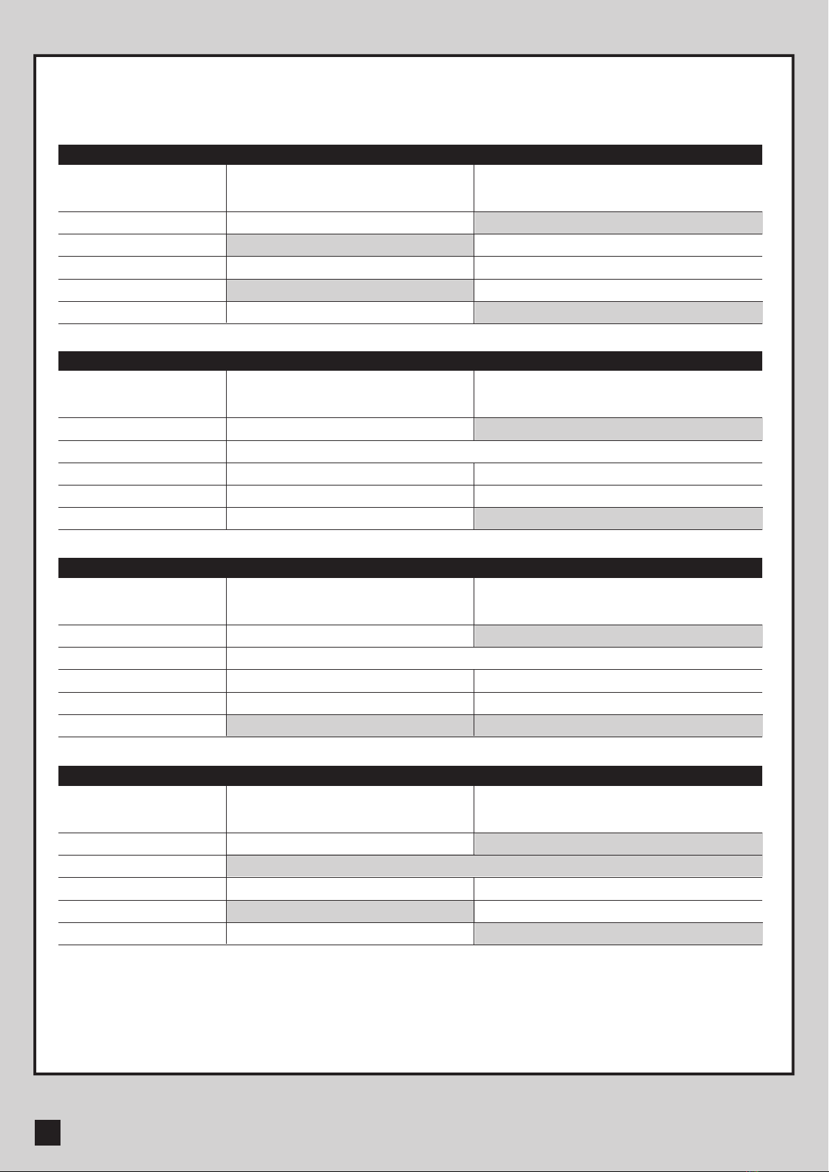
BTECHNICAL FEATURE:
Model
Motor
Gear type
Nominal thrust
Maximum Gate Weight
Maximum Gate Length
Operating Temperature
Dimension
Weight
PAPILLON 250
24Vdc motor
Electromechanical worm gear
1200N
250 kg per leaf
2.5 meters per leaf
-20oC~+50oC
256 x 187 x 267mm
6 kg
Model
Main power supply
Back-up battery
Receiver board
Installation
Operating Temperature
Dimension
CB19
230Vac/110Vac, 50Hz/60Hz
2pcs of batteries for emergency operation, 1.2A each
433.92MHz; 200 transmitters memory
Wall mounted vertically
-20oC~+50oC
275mm x 195mm x 102mm
This manual suits for next models
1
Table of contents
Other TMT Automation Gate Opener manuals


Popular Gate Opener manuals by other brands

Mighty Mule
Mighty Mule Mighty Mule installation manual

Chamberlain
Chamberlain LA412PKGUL instruction manual

Chamberlain
Chamberlain LC-36A quick start guide

Genius
Genius TRIGON 02 GUIDE FOR THE INSTALLER

Biketronics
Biketronics CribClicker BT385 installation guide

Chamberlain
Chamberlain LA500UL installation manual


tau
tau T-SKY Use and maintenance manual

Automatic Technology Australia
Automatic Technology Australia Elite installation instructions

HySecurity
HySecurity StrongArmPark DC Programming and operations manual

HySecurity
HySecurity SlideSmart DC Quick start steps

GiBiDi
GiBiDi TAIMEN T6 Instructions for installation

GiBiDi
GiBiDi FLOOR 830 manual