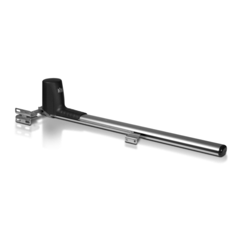
DITEC CS 61E Manual

Manuale di installazione e
manutenzione per
automazioni per cancelli
scorrevoli.
Installation and mainte-
nance manual for sliding
gate automatic system .
Manuel d'installation et
d'entretien pour
automatisme pour portails
coulissants
Montage und Wartungs-
handbuch für Schiebetore
Automatisierung
Manual de instalaciòn y
manutenciòn para
automatizaciòn de
cancelas de corredera.
CS 61E / CS 61
IP1580 30/06/99

2
DITEC S.P.A - IP1580 30/06/99 - CS61/CS61E
Installazione tipo .............................................................................................................................................. pag. 3
Illustrazioni ....................................................................................................................................................... pag. 4-5
Avvertenze generali per la sicurezza................................................................................................................ pag. 6
Dati tecnici......................................................................................................................................................... pag. 7
Riferimenti illustrazioni .................................................................................................................................... pag. 7
Installazione.......................................................................................................................................................pag. 7
Collegamenti elettrici CS61E ............................................................................................................................pag. 8
Avviamento........................................................................................................................................................ pag. 9
Collegamenti elettrici CS61.............................................................................................................................. pag. 9
Piano di manutenzione..................................................................................................................................... pag. 9
Ricerca guasti .................................................................................................................................................. pag. 9
Istruzioni d’uso.................................................................................................................................................. pag. 10
Standard installation ........................................................................................................................................ page 3
Illustration.......................................................................................................................................................... page 4-5
General safety precautions .............................................................................................................................. page 11
Technical data.................................................................................................................................................... page 12
Reference to illustrations..................................................................................................................................page 12
Installation..........................................................................................................................................................page 12
Electrical connections CS61E...........................................................................................................................page 13
Starting-up..........................................................................................................................................................page 14
Electrical connections CS61............................................................................................................................. page 14
Maintenance program........................................................................................................................................page 14
Trouble shooting .............................................................................................................................................. page 14
Operating instruction.........................................................................................................................................page 15
Installation type ............................................................................................................................................... page 3
Elements .......................................................................................................................................................... page 4-5
Consignes generales de securité..................................................................................................................... page 16
Donnees tecniques............................................................................................................................................page 17
Elements....................... .................................................................................................................................... page 17
Installation......................................................................................................................................................... page 17
Raccordement electriques CS61E.................................................................................................................... page 18
Demarrage......................................................................................................................................................... page 19
Raccordement electriques CS61..................................................................................................................... page 19
Entretien periodique......................................................................................................................................... page 19
Recherche pannes ........................................................................................................................................... page 19
Instructions d’utilisation................................................................................................................................... page 20
Standard Montage ............................................................................................................................................ pag. 3
Abbildungen ..................................................................................................................................................... pag. 4-5
Allgemeine Sicherheitshinweise...................................................................................................................... pag. 21
Technischen Daten............................................................................................................................................ pag. 22
Verweis auf Abbildungen................................................................................................................................. pag. 22
Montage............................................................................................................................................................. pag. 22
Elektrische Anschlüsse CS61E........................................................................................................................ pag. 23
Anlauf................................................................................................................................................................ pag. 24
Elektrische Anschlüsse CS61.......................................................................................................................... pag. 24
Regelmässige Instandhaltung.......................................................................................................................... pag. 24
Fehlersuche ...................................................................................................................................................... pag. 24
Bedienungsanleitung.........................................................................................................................................pag. 25
Installaciòn tipo ................................................................................................................................................ pàg. 3
Elementos ........................................................................................................................................................ pàg. 4-5
Advertencias generales de seguridad............................................................................................................. pàg. 26
Datos tecnicos................................................................................................................................................... pàg. 27
Referencias de las ilustraciones...................................................................................................................... pàg. 27
Installacion........................................................................................................................................................ pàg. 27
Conexiones eléctricas CS61E ..........................................................................................................................pàg. 28
Arranque ........................................................................................................................................................... pàg. 29
Conexiones eléctricas CS61. .......................................................................................................................... pàg. 29
Mantenimiento.................................................................................................................................................. pàg. 29
Busqueda de averias ....................................................................................................................................... pàg. 29
Instrucciones de uso.........................................................................................................................................pàg. 30
INDICEINDEXINDEXANGABEINDICE

3DITEC S.P.A - IP1580 30/06/99 - CS61/CS61E
Fig. 1
Impianto tipo
Standard installation
Installation type
Standard Montage
Instalaciòn tipo
I
UK
F
D
E
TX - 4x0.5 mm²
RX-4x0.5 mm²
4x0.5 mm²
1
3
2
5
3x1.5 mm²
2x1.5 mm²
4
8
5
66
7

4
DITEC S.P.A - IP1580 30/06/99 - CS61/CS61E
fig. 2
200 9520
315
200
100
110
275
fig. 3
913 12 11 10
15
14
fig. 4 fig. 5
80
200
130
270
max 5 mm
B
DE
F
G
min. 30

5DITEC S.P.A - IP1580 30/06/99 - CS61/CS61E
2÷3
fig. 6 fig. 7
fig. 8
~20
fig. 9 fig. 10DIP1 OFF DIP1 ON
H
M
1~
U
W
V
NERO / BLACK
C
16 µF
A
BLU / BLUE
BIANCO/WHITE
NERO / BLACK
BLU / BLUE
BIANCO/WHITE
CS61
com
FC1 / 11
FC2 / 12
COM / 0
fig. 11

11 DITEC S.P.A - IP1580 30/06/99 - CS61/CS61E
DECLARATION BY THE MANUFACTURER
(Directive 98/37/EC, Annex II, sub B)
Manufacturer: DITEC S.p.A.
Address: via Mons. Banfi, 3 - 21042 Caronno Pertusella (VA) - ITALY
Herewith declares that the electromechanical automatic system series CS61E-CS61
- is intended to be incorpored into machinery or to be assembled with other machinery to constitute machinery convered by Directive
98/37/EC, as amended;
- is in conformity with the provisions of the following other EEC directives:
Electromagnetic Compatibility Directive 89/336/EEC, as amended;
Low Voltage Directive 73/23/EEC, as amended;
and furthermore declares that it is not allowed to put the machinery into service until the machinery into which it is to be incorporated or
of which it is to be a component has been found and declared to be in conformity with the provisions of Directive 98/37/EC and with
national implementing legislation.
Caronno Pertusella, 03/06/1999. Fermo Bressanini
(Chairman)
ENGLISH
GENERAL SAFETY PRECAUTIONS
This installation manual is intended for professionally competent personnel only.
The installation, the electrical connections and the settings must be completed in conformity with good workmanship and
with the laws in force.
Read the instructions carefully before beginning to install the product. Incorrect installation may be a source of danger.
Packaging materials (plastics, polystyrene, etc) must not be allowed to litter the environment and must be kept out of the reach of children
for whom they may be a source of danger.
Before beginning the installation check that the product is in perfect condition.
Do not install the product in explosive areas and atmospheres: the presence of flammable gas or fumes represents a serious threat to
safety.
Before installing the motorisation device, make all the structural modifications necessary in order to create safety clerance and to guard
or isolate all the compression, shearing, trapping and general danger areas.
Check that the existing structure has the necessary strength and stability.
The manufacturer of the motorisation device is not responsible for the non-observance of workmanship in the costruction of the frames to
be motorised , nor for deformations that may be occur during use.
The safety devices (photoelectric cells, mechanical obstruction sensor, emergency stop, etc) must be installed taking into account: the
provisions and the directives in force, good workmanship criteria, the installation area, the funtional logic of the system and the forces
developed by the motorised door or gate.
The safety devices must protect against compression, shearing, trapping and general danger areas of the motorized door or gate.
Display the signs required by law to identify danger areas.
Each installation must bear a visible indication of the data identifying the motorised door or gate.
Before connecting to the mains check that the rating is correct for the destination power requirements.
A multipolar isolation switch with minimum contact gaps of 3 mm must be included in the mains supply.
Check that upstream of the electrical installation there is an adequate differential switch and a suitable circuit breaker.
Ensure that the motorised door or gate has an earth terminal in accordance with the safety regulations in force.
The manufacturer of the motorising device declines all responsability in cases where components which are incompatible with the safe
and correct operation of the product only original spare parts must be used.
For repairs or replacements of products only original spare parts must be used.
The fitter must supply all information corcerning the automatic, the manual and emergency operation of the motorised door or gate, and
must provide the user the device with the operating instructions.
MACHINERY DIRECTIVE
Pursuant to Machinery Directive (98/37/EC) the installer who motorises a door or gate has the same obligations as the manufacturer of
machinery and as such must:
- prepare the technical file which must contain the documents indicated in Annex V of the Machinery Directive; (The technical file must
be kept and placed at the disposal of competent national authorities for at least ten years from the date of manufacture of the
motorised door);
- draft the EC declaration of conformity in accordance with Annex II-A of the Machinery Directive;
- affix the CE marking on the power operated door in accordance with point 1.7.3 of Annex I of the Machinery Directive.
For more information consult the “Technical Manual Guidelines” available on Internet at the following address: http://www.seisnet.it/ditec/
APPLICATIONS
Maximum permissible weight: 600 kg
Recommended weight: 400
Service life: 3 (minimum 10÷5 years of working life with 30÷60 cycles a day)
Applications: FREQUENT (For vehicle or pedestrian accesses to town houses or small condominiums with frequent use).
Minimum number of consecutive cycles: 15
• Performance characteristics are to be understood as referring to the recommended weight (approx. 2/3 of maximum permissible
weight). A reduction in performance is to be expected when the access is made to operate at the maximum permissible weight.
• Service class, running times, and the number of consecutive cycles are to be taken as merely indicative having been statistically
determined under average operating conditions, and are therefore not necessarily applicable to specific conditions of use. During
given time spans product performance characteristics will be such as not to require any special maintenance.
• The actual performance characteristics of each automatic access may be affected by independent variables such as friction, balancing
and environmental factors, all of which may substantially alter the performance characteristics of the automatic access or curtail its
working life or parts thereof (including the automatic devices themselves). When setting up, specific local conditions must be duly
borne in mind and the installation adapted accordingly for ensuring maximum durability and trouble-free operation.

12
DITEC S.P.A - IP1580 30/06/99 - CS61/CS61E
1. TECHNICAL DATA
Powersupply 230 V~ 50 Hz
Absorption 2 A
Motor power 250 W
Torque 700 N
Max. run 13 m
Max. door weight 600 kg
Speed 0.18 m/s
Intermittence S2 = 15 min. / S3 = 25%
Temperature -15 °C / +50 °C
Degree of protection IP54
Weight 12.7 kg
2. REFERENCE TO ILLUSTRATIONS
2.1 Standard installation references (fig. 1)
ATTENTION: Only use DITEC’s safety devices and accessories for installation.
1 Radio
2 Flashing light
3 Key selector
4 Connectpower supply toan omni-pole switch witha contact openinggapof no lessthat 3 mm (notsupplied
by us)
2.2 Geared motor references (fig. 2)
9 Geared motor
10 Carter
11 Release access door
12 Release
3. INSTALLATION
3.1 Preliminary checks
Check for gate stability and that the slide wheels are in good condition and the top guides do not cause any
friction. The slideway must be securely anchored to the ground and fully exposed along its full length. It must be
perfectly smooth so as to avoid jamming of the gate.
Provide an opening and closing stop.
Make sure that the gate is securely inserted in the slideway so that it cannot come out of the
slideway and fall.
Geared motor installation
Unless otherwise specified, all measurements are expressed in millimetres.
3.2 (Fig. 4) Lay a concrete foundation with buried anchoring brackets and the base plate, making sure that it is
pefectly level and smooth. Allow for 80 mm between the plate axis and the rack B . Route the cable ducts
through the two holes in the middle of the plate.
3.3 (Fig. 5) Open the release access door 11 , loosen the screw that locks the carter and lift it. Insert the
ancoring feet G at the gear motor base. Position the geared motor on to the base plate. Adjusting
gearmotor: horizontally by sliding in the ancoring feet notches, vertically with the 4 levelling screws D :
while adjusting vertically, keep the motor slightly raised above the base plate so as to allow enough
space to secure the rack and to make any subsequent adjustments, if necessary.
3.4 (Fig. 6) Secure the rack by disengaging the geared motor and opening the gate. Place the rack on pinion
15 and move the gate manually to secure the rack along its full length. Once the rack has been secured,
verticallyadjust the geared motorso as to havea gap of 2to 3 mm betweenthe pinion and therack. Finally,
firmly secure the geared motor by fitting shims E and washers F .
3.5 (Fig. 7, 8) Adjusting limit switch: secure the limit stop skids H on to the rack so that the gate stops about
20 mm before reaching the stop.
ENGLISH
5 Geared motor + Electrical board
6 Photocells
7 Rubber hip / Sensitive hip
8 Opening and closing stop
13 Electrical board
14 Limit-switch spring
15 Pinion

13 DITEC S.P.A - IP1580 30/06/99 - CS61/CS61E
WARNING: Link up all N.C. contacts (if not used) by means of jumpers.
The terminal bearing the same number are equivalent.
ENGLISH
4. ELECTRICAL CONNECTIONS CS61E
4.1 Controls
CONTACT FUNCTION DESCRIPTION
15(N.O.) STEP BY STEP With TC at maximum: “open-stop-close” sequence.
With TC not at maximum: “open-close/automatic
closure” sequence. The closing control can operate
when the gate is standing opened.
16(N.C.) STOP SAFETY It stops and/or prevents any movement.
CONTACT
18(N.C.) REVERSAL SAFETY Reverses movement (re-opens) during closing.
CONTACT When door is not moving, inhibits all operation.
19(N.C.) EMERCENCY Byopeningthe 1-9 contact thegatestops or remains
STOP still and the automatic closing is disabled.
REMOTE CONTROL STEP BY STEP It has the same function as the 1-5 control.
Parallel connection Thismodeldoesnot permit the running of twomotors
of automatic controls in parallel.
4.2. Output and accessories
1 + Accessories power supply. 24V / 0.15A (nominal) / 0.3 A (peak) output
0- for powering of external accessories including gate state lamp.
1 11 Lamp (24 V / 1.5 W) gate open with DIP1 ON, closed gate lamp with
DIP1 OFF.
1 12 Lamp (24 V / 1.5 W) gate close with DIP1 OFF, open gate lamp with
DIP1 ON.
W N Flashing light. 230 V~/ 100 W max. output. Itis lighting during theopening
and closing operation. With automatic closure mode the flashing begins
3 s before the end of the setted time of TC, with TC lesser 3 s the flashing
lasts as long as the break time.
F1 F2
Q.E. D61
LN UWV 1211015689
230 V~
M
1 ~
FC2
FC1
COM
16 µF
RF TC R1 DIP1
Limit switch
Release micro
Limit switch
ON
OFF
+
-
24 V / 0.15 A F1 = F5 A line
F2 = F315 mA accessories
CONTROL BOARD
com

14
DITEC S.P.A - IP1580 30/06/99 - CS61/CS61E
ENGLISH
4.3 Setting and adjustments
TC - Automatic closure time. From 0 to 120 s, with TC from 0 to 3/4 turn. The counting begins:
- at the end of the opening operation and lasts as long as the time set on the TC trimmer;
- after a safety device has operated (1-6 / 1-8) and lasts half the time set on the TC.
TCatmaximum disable the automatic closure.Warning: thepositionofTC (which enables or disablesautomatic
closing ) also selects the function of control 1-5.
RF - Power adjustment. Setting of RF from min to max selects min to max power. The motor always starts up
at max power and after 1 s switches over to the power set via RF.
R1 - Obstacle detection adjustment. The electric board is fitted with a safety device which, in case of an
obstacle being detected, causes the gate to stop moving when it is opening and to reverse movement when it is
closing. With trimmer R1 at minimum there is maximum sensitivity. With R1 at maximum the function is cut out.
DIP1 - Selection of movement direction OFF = opening toward the right, ON = opening toward the left (see
fig. 9 and 10).
5. STARTING UP
WARNING: the operations regarding point 5.2 are without safety devices.
the trimmer can only be adjusted with gate not moving (RF excluded).
5.1. Set TC, RF and R1 at maximum. Short circuit the safety devices and the stop device. Select desired
movement direction by means of DIP1 (see fig. 9 and 10).
5.2.Power and check thegate functions correctly witha sequence of step-by-stepcommands. Check the action
of the limit switches.
5.3. Remove the jumpers and connect the safety devices (1-6 and 1-8) and the stop (1-9). Check their function.
5.4. Adjust the automatic closure with TC. Warning: the automatic closure time after the operation of one of
the safety devices is half the set time.
5.5. Put RF in the position which ensures functioning and the safety of the user.
5.6. After having set RF, set the obstacle detection sensitivity with R1.
5.7. Connect any accessories and check their function.
5.8. Re-fit the casing and make sure that the stop microswitch tripped by release door 11 is properly operating.
6. ELECTRICAL CONNECTION CS61
Connect the motor and limit switches to the control panel as in figure 11. A and C refer to opening and clos-
ing limit switch.
7. TROUBLE SHOOTING
8. MAINTENANCE PROGRAM (each 6 month)
Power off (230 V~ mains and batteries, if installed)
- Check gate/gear motor alignment and the distance (2-3 mm) between the mouth of the pinion and the crest of the rack.
- Clean the wheel slideways, the rack and the pinion of the geared motor.
Power on (230 V~ mains and batteries)
- Check the functioning of the limit switches (the gate must come to a halt ~ 20 mm before the stop)
- Check the power adjustments.
- Check the operation of all command and safety functions (photocells).
ATTENTION: For spare parts, see the spares price list.
PROBLEM
Gate fails to open and close.
Gate opens but fails to close.
External safeties fail to trigger.
Flashing light not work.
POSSIBLE CAUSE
Power failure.
F1/F2 fuse blown.
Safety contacts open.
Geared motor released.
Radio control not working.
Safety contacts open.
Photocells activated.
Automatic closure not working.
Incorrect wiring between photocells and the
Electric Board.
Bulb blown.
REMEDY
Check for power supply from mains.
Change fuse.
Check terminals 6, 8 and 9 in the E. B.
Check that release door is locked and that
release microswitch is pressed.
Check for proper installation and activation of
the radio device (TX and RX).
Check terminal 8 of the E.B.
Check that photocells are clean and properly
working
Check that TC trimmer is not set to maximum.
Connect N.C. safety contact in series and
remove any jumpers.
Replace with a 230 V bulb.

ENGLISH
TEAR OFF AND DELIVER TO USER
DITEC S.p.A.
Via Mons. Banfi, 3
21042 Caronno P.lla (VA) Italy
Tel.02/963911 - Fax 02/9650314
www.ditec.it
Operating instruction CS61E, CS61
ISO 9001 - Cert. n° 0957/0
Automation for sliding gates
GENERAL SAFETY PRECAUTIONS
The following precautions are an integral and essential part of the product and must be supplied to the user.
Read them carefully as they contain important indications for the safe installation, use and maintenace.
These instruction must be kept and forwarded to all possible future user of the system. This product must be used only for that which it has
been expressely designed. Any other use is to be considered improper and therefore dangerous.
The manufacturer cannot be held responsible for possible damage caused by improper, erroneous or unresonable use.
Avoid operating in the proximity of the hinges or moving mechanical parts. Do not enter the field of action of the motorised door or gate
while in motion. Do not obstruct the motion of the motorised door or gate as this may cause a situation of danger.
Do not lean against or hang on to the barrier when it is moving.
Do not allow children to play or stay within the field of action of the motorised door or gate.
Keep remote control or any other control devices out of the reach of children, in order to avoid possible involuntary activation of the
motorised door or gate. In case of breack down or malfunctioning of the product, disconnect from mains, do not attempt to repair or
intervene directly and contact only qualified personnel. Failure to comply with the above may create a situation of danger.
All cleaning, maintenance or repair work must be carried out by qualified personnel.
In order to guarantee that the system works efficiently and correctly it is indispensable to comply with the manufacturer’s indications thus
having the periodic maintenance of the motorised door or gate carried out by qualified personnel.
In particular regular checks are recommended in order to verify that the safety devices are operating correctly.
All installation, maintenance and repair work must be documented and made available to the user.
RELEASE INSTRUCTION
Incase of faultyoperation or powerfailure, insert androtate the keyanticlockwise. Open the door and rotate the
release knob anticlockwise. Manually slide the gate open
To re-lock the gate, rotate the knob clockwise without tightening, slightly move the gate and finally fully tighten
down the knob. To return to automatic mode, lock the door with the key.
WARNING: If the door is opened, the limit switch common is opened thus preventing all operations.
This manual suits for next models
1
Table of contents
Other DITEC Gate Opener manuals

DITEC
DITEC LUXO3BH E2H User manual

DITEC
DITEC COM502ES User manual

DITEC
DITEC OBBI User manual

DITEC
DITEC Arc Series Manual

DITEC
DITEC 0DT848 User guide

DITEC
DITEC TRAFFIC C User guide

DITEC
DITEC CROSS35 User manual

DITEC
DITEC TRAFFIC C User guide

DITEC
DITEC 0DT872 User guide

DITEC
DITEC FACIL Series User manual
Popular Gate Opener manuals by other brands

Beninca
Beninca RI.15T Operating instructions and spare parts catalogue

BFT
BFT BAT installation manual

CAME
CAME OPB001CB installation manual

Nortek Security & Control
Nortek Security & Control Mighty Mule HD272 installation manual

CAME
CAME Ferni Series Manaul

Ghost Controls
Ghost Controls TDS2 Installation and owner's manual