Merlino FUTURA S Series User manual
USER MANUAL
Designed and produced in accordance with EEC directives
MERLINO elettronica s.a.s. di Meroni N.
Via Como, 33/A - 20035 Lissone - MB
E-mail: [email protected]
Web-site: www.merlinoelettronica.it
ITALIA-UE Tel & Fax ++39-039-2450296
Partita I.V.A. e Codice Fiscale 03398650964
Pag. 1
MISU_UK-0642 - 2.0
“FUTURA-S”
SERIES
ACTIVE OPTO-ELECTRONIC
PROTECTIVE DEVICE “AOPD”
IN COMPLIANCE WITH THE
MACHINERY DIRECTIVE
2006/42/EEC
2006/42
PREFACE
This manual provides the user and/or installer with the information required for correct use
of the "FUTURA" device in the application for which it was designed, and in safety and risk-
prevention.
The manual must be kept carefully in such a way as to be immediately available should it be
required.
Contact the manufacturer for clarification, explanations or additional copies or updates of
the manual itself.
The manufacturer reserves the right to vary products and the manual without being
obliged to update previous products and manuals.
MISU_UK 2.0 - Revision 2.0 of 14-April-2010

CONTENTS
2
PAG.1
PAG.2
PAG.3
PAG.4
PAG.5
PAG.6
PAG.7
PAG.8
PAG.9
PAG.10
PAG.11
PAG.12
PAG.13
PAG.14
PAG.15
PAG.16
PAG.17
PAG.18
Pag. 2
PROGETTAZIONE E PRODUZIONE
APPARECCHIATURE ELETTRONICHE
MERLINO elettronica s.a.s. di Meroni N.
Via Como, 33/A - 20035 Lissone - MI
E-mail: [email protected]
Web-site: www.merlinoelettronica.it
1. Preface ......................................................................................
2. Contents ...................................................................................
3. Warranty - Supplied material ................................................
4. Legend ......................................................................................
5. Precautions ..............................................................................
6. Installation - FUTURA3/FUTURA4 ........................................
7. Light indicators and setting controls - TX ............................
.
7.1 Light indicators and setting controls - RX ............................
8. Rating plate ..............................................................................
9. Determining the safe distance ...............................................
10. Technical characteristics - FUTURA14 FUTURA38 .............
10.1 Technical characteristics - FUTURA76 FUTURA114 ...........
11. Electrical connections - TX .....................................................
11.1 Electrical connections - RX .....................................................
12. Mechanical data .......................................................................
13. Maintenance and controls - Spare parts ..............................
14. How to order ............................................................................
15. Declaration of conformity .......................................................
MISU_UK-0642 - 2.0
WARRANTY
3
4
Pag. 3
PROGETTAZIONE E PRODUZIONE
APPARECCHIATURE ELETTRONICHE
MERLINO elettronica s.a.s. di Meroni N.
Via Como, 33/A - 20035 Lissone - MI
E-mail: [email protected]
Web-site: www.merlinoelettronica.it
The warranty
MATERIALSUPPLIEDASSTANDARD
is valid for a period of 12 months from the consignment date and expires at the
end of this period, irrespective of whether the appliance has in fact been used. The guarantee
covers all parts of the device if the materials or assembly of said parts are shown to be faulty and
in respect of the following conditions:
The warranty covers replacement of all those parts shown to be of faulty manufacture
under normal conditions of use.
The warranty is not valid unless accompanied by a copy of the invoice proving purchase.
The warranty is not valid in the following cases:
a if the device has been tampered with in any way;
b use of the device in ways not conforming to the instructions and warnings
given in this manual;
c damage caused by an unsuitable working environment or phenomena not
dependent on normal operation (e.g. an unsuitable mains voltage and/or
frequency values);
d repairs carried out by persons or technical assistance centres not authorised
by the manufacturer.
The resulting costs and risks associated with transport, packing and labour are the
responsibility of the purchaser.
The replacement of the device and/or extension of the period of guarantee validity
following a fault are excluded.
Compensation will not be paid for damages occurring as a result of the device being
inoperative while repairs are carried out.
Where not explicitly specified, reference should be made to 85/374/EEC on the
responsibility for faulty products as incorporated in Italian Decree D.P.R. 224 of 1998.
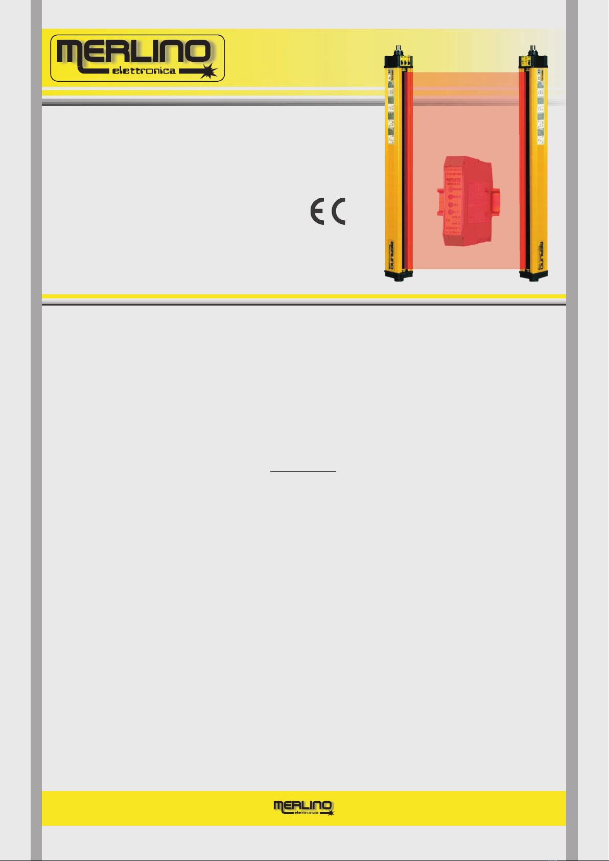
The "FUTURA" invisible optoelectronic active infrared light curtain consists of the following
elements supplied suitably packed:
Transmitter (TX) complete with M12 5 pole output connector with 5 m long cable
Receiver (RX) complete with M12 8 pole output connector with 5 m long cable
Copy of the present manual including the “ DECLARATION OF CONFORMITY”
Adjustable brackets for installing the Transmitter TX and Receiver RX.
MISU_UK-0642 - 2.0

LEGEND
4
Pag. 4
PROGETTAZIONE E PRODUZIONE
APPARECCHIATURE ELETTRONICHE
MERLINO elettronica s.a.s. di Meroni N.
Via Como, 33/A - 20035 Lissone - MI
E-mail: [email protected]
Web-site: www.merlinoelettronica.it
FUTURA
ESPE
OSSD
TX
RX
EDM
=
=
= Trans
)
= R
=
Elettro Sensitive Protective Equipment
Output Signal Switching Device=
=950 nm
name of the device covered by this manual
mitter (section of the “FUTURA
” light curtain emitting IR radiation with
a wavelength of
eceiver (section of the "FUTURA" acting as a sensor and com
and control device and incorporating the two OSSDs).
component monitoring the contacts efficiency of devices connected externally
to the outputs of the light curtain (External Device Monitor).
light curtain
mand
P
W
T
RXTX
PH
PD
PA
DC
WD
=
=
= PH x PD =
=
=
protected by the invisible IR curtain generated by the "FUTURA" device
protected with the declared detection capability (DC)
protected area
detection capability (eg. 14, 38, 76 etc.)
working distance of the two sections: Transmitter TX and Receiver RX
height
distance
Test piece to control
detection capability
To calculate the distance actually
protected with the detection
capability (DC) declared on the
rating plate, use the following
formula, replacing the parameters
with the values corresponding to
your specific application:
where N is a function of the
protected and the detection
capability of the light curtain
according to the formula:
height
Fig.1
VERIFYINGTHEPROTECTEDAREA
RUN ALT
This should be performed using a cylindrical test piece with a diameter corresponding to the
detection capability of the device concerned. This must be intercepted anywhere within the
protected area, causing the green LED to light off and the red LED to light on.
The output signal switching devices (OSSDs) should also open, disabling operation of the
machine. A test piece suitable for the device in use should always be available near the work
station.
MISU_UK-0642 - 2.0

PRECAUTIONS
5
Pag. 5
PROGETTAZIONE E PRODUZIONE
APPARECCHIATURE ELETTRONICHE
MERLINO elettronica s.a.s. di Meroni N.
Via Como, 33/A - 20035 Lissone - MI
E-mail: [email protected]
Web-site: www.merlinoelettronica.it
The "FUTURA" device has been designed and produced with the aim of eliminating or reducing
as far as possible all risks for the user. However, could result in unforeseen
conditions with some degree of danger which cannot be completely eliminated. Installation,
testing and maintenance of the "FUTURA" device must be performed exclusively by qualified
personnel following the instructions in this manual faithfully and meticulously.
The and housings are electrically connected to the earth of the internal circuit, thus to the
conductor of the connector. Contact between the housing and the chassis of the machine
(unless free of potential) must therefore be avoided. Failure to observe this precaution could
lead to damage of the units. This danger is totally avoided if the sensor units are correctly fixed by
means of the special adjustable insulating "L" brackets (or by means of optional rear shock
absorbing cylinders).
Connection of other equipment to the power source used to power the "FUTURA" device is not
recommended. This could generate electrical disturbance, jeopardising correct operation of the
various parts of the device itself.
If liquid or foreign bodies of any kind penetrate the device, stop using it immediately and
disconnect it from the power supply.
The “FUTURA” device has been designed and produced in such a way that the housing does not
have to be opened for the device to be used. Given the particular function of the device itself,
removal of the heads of the aluminium housings of the transmitter TX and receiver RX is
prohibited. No attempt should be made to repair them. Always contact the manufacturer only.
improper use
MECHANICALWARNINGS
To prevent shift of the light curtain and consequently also of the protected field, it must be fixed
solidly and precisely respecting the instructions given in paragraph 12 "Mechanical Data".
Connection cables must be arranged so as to avoid accidental contact with, for example,
abrasive, hot or sharp objects which could cause dangerous damage to the cables themselves.
In the event of damage to the connection cables, do not use the device and disconnect
immediately from the power supply. Avoid the connection cables coming into contact with water
or damp surfaces.
For increased safety, shiny surfaces near the light curtain should be opacified. While in
operation, avoid the presence of any infrared diffusing translucent screen in the protected area
as failure to calibrate the light curtain precisely or installation beyond the specified distance
could create detection uncertainty. Mark the extent of the protected area with a material
boundary. If this is not possible, increase the installation distance between the TX and RX to
ensure that the entire area providing access to the danger zone is safely included in the
protected distance PD. Use barriers with a protected height PH such as to prevent the operator
from reaching the danger zone above the upper limit or below the lower limit. In addition, prevent
access to the danger zone with other fixed material barriers where this is not possible by the use
of electro sensitive protective devices.
ELECTRICALWARNINGS
TX RX
GND
MISU_UK-0642 - 2.0

INSTALLATION
6
Pag. 6
PROGETTAZIONE E PRODUZIONE
APPARECCHIATURE ELETTRONICHE
MERLINO elettronica s.a.s. di Meroni N.
Via Como, 33/A - 20035 Lissone - MI
E-mail: [email protected]
Web-site: www.merlinoelettronica.it
Ensure the two units, TX and RX, are perfectly parallel and fix using the special adjustable
insulating brackets at the working distance specified when ordering and reported on the rating
plate under the heading "Working Distance". Keep the Receiver out of direct sunlight.
The equipment is turned on by powering the transmitter TX and receiver RX according to the
information given on the rating plate. After about one second the device should be ready for
operation. The meaning of the light indicators is described and illustrated in detail in paragraph 7
".
After turning power to the two units on and aligning them correctly, make sure that at least the
yellow indicator on the TX and the green indicator on the RX are on. The red
indicator on the RX lights on in the presence of an obstacle inside the protected area or if the units
are not perfectly aligned. To prolong the connections, use shielded cable to avoid all
interference.
If there are shiny reflectant surfaces near the light curtain, they should ideally be coated with matt
black paint to reduce the risk of undesirable reflections.
The sensor units are normally factory calibrated for the distance requested. However, in certain
cases it may be necessary to recalibrate on site using the " " buttons on the front panel
of the top head of the emitter TX. This should be done starting from the lowest value, repeatedly
pressing the button while holding the button down until all three LEDs on the buttons
light off. At this point, without intervening in the protected zone and in the total absence of obsta
cles, repeatedly press the button only for just the number of times necessary for the green
indicator on the RX to lights on steadily. This must be performed at least twice together with
reciprocal alignment of the two sensor units. The final position of the digital compara
tor will therefore be that nearest to the GREEN RED switch point of the indicators.
Finally press the button to confirm and store the new calibration. This operation produces
the best calibration obtainable for the distance considered.
This procedure must be performed by specialist accident prevention personnel supervised by
the company safety manager who will previously have contacted the manufacturer.
stan
dard
"Light indicators and setting controls
DISTANCE
MIN RUN ALT
DISTANCE
INC DEC
INC
RUN
RUN ALT-
Also verify correct operation using the test piece to ensure it is intercepted at all points of the area
to be protected. The minimum diameter of the test piece unequivocally intercepted at all points of
the protected area is known as the Maximum Detection Capability (from IEC EN 61496
) of the light curtain. For example, for the FUTURA 38 system this is 38 mm.
The choice between the two models must be made on the basis of the risk category attributed to
the machine, assessed in accordance with European standard . The model
is suitable for all applications with maximum accident risk, both in terms of the frequency with
which the operator is exposed to said risk and the gravity of the danger (machines listed in annex
IV of Directive 98/37). The model is suitable for all other applications where the severity
and frequency of exposure to the risk of accident is less.
EN954-1 FUTURA4
FUTURA3
SET
FUTURA3 -FUTURA4
MISU_UK-0642 - 2.0
LIGHT INDICATORS and SETTING CONTROLS - TX
7
Pag. 7
PROGETTAZIONE E PRODUZIONE
APPARECCHIATURE ELETTRONICHE
MERLINO elettronica s.a.s. di Meroni N.
Via Como, 33/A - 20035 Lissone - MI
E-mail: [email protected]
Web-site: www.merlinoelettronica.it
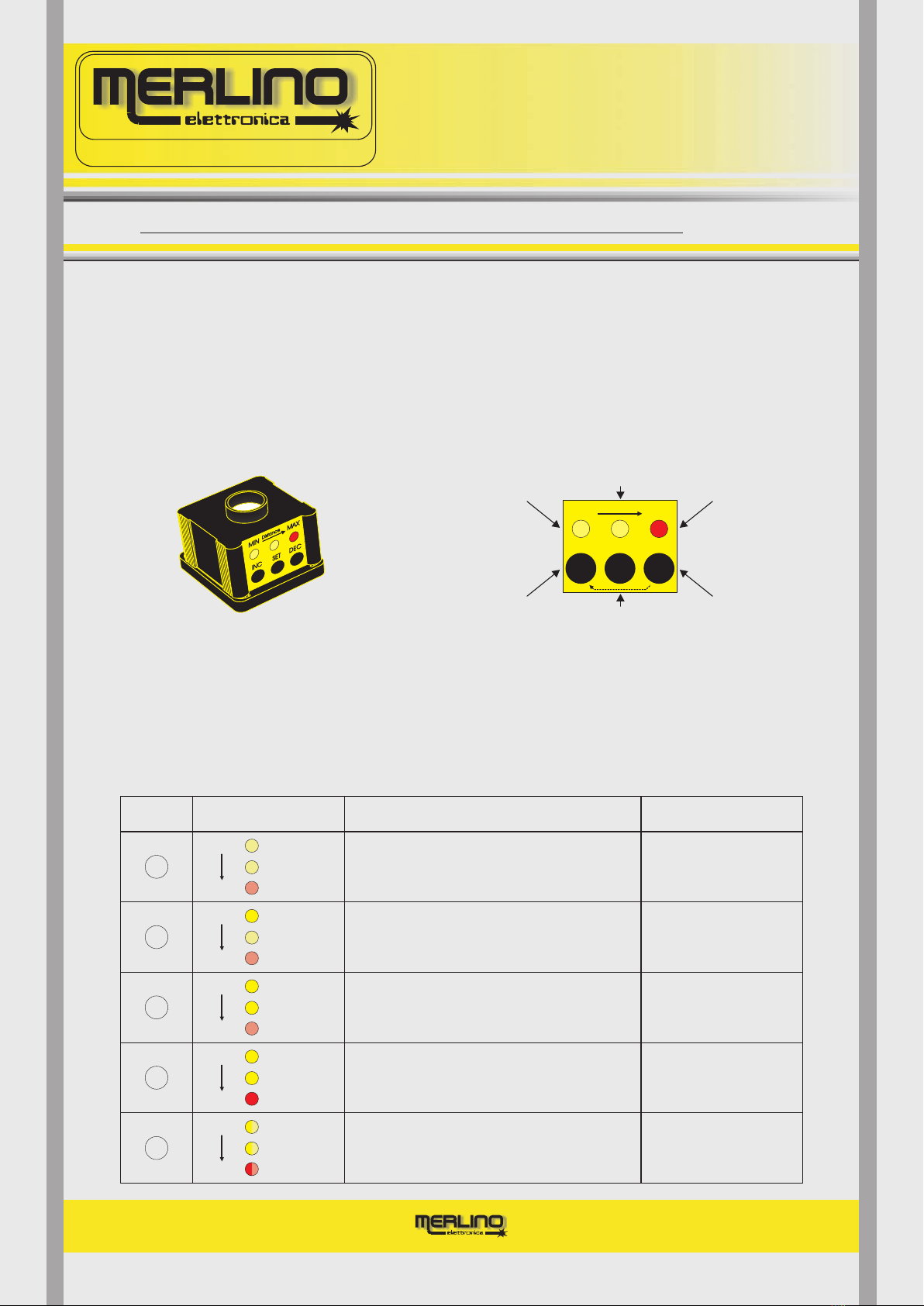
The "FUTURA" active optoelectronic light curtain has a number of light indicators providing
rapid and unequivocal information on its operating status. In particular, there are three LEDs
on the top head of the transmitter (TX) and five on the top head of the receiver (RX).
There are also a number of controls to set and regulate the emitter and receiver. To ensure their
correct use, they are identified and described below.
INC
SET
DEC
button: modifies the working distance. Press repeatedly a maximum of 30 times to increase or decrease (if the button is held down at the
same time) the distance up to the maximum or down to the minimum allowed for that specific model.
button: confirms the working distance. Press once to maintain the set working distance (until pressed again) also after having disconnected
from the power supply.
button: decreases the working distance. If held down while the button is pressed, reducesthe working distance to the minimum allowed for
that specific model.
DEC
INC
Setting controls (absent in the /AUTO model)
T
NA
Fig.2
INC DEC
SET
MIN Distance MAX
Indicates short
distance calibra.
light-curtain
Indicates medium
distance calibrated
l i g h t - c u r t a i n Indicates long
distance calibra.
light-curtain
Push-button to
increase and
decrease distance
Push-button
to confirm
distance
Psh-button
to decrease
distance
Fig.3
CHECK AND
SOLUTION
A
B
C
DEVICE STATUS
D
LEDs STATUSCASE
No power.
Possible internal fault
Calibrated for minimum
working distance
Check the suitability of
the installation distance
Calibrated for medium
working distance
Calibrated for maximum
working distance
OFF
OFF
OFF
MAX
MIN
OFF
OFF
ON
MAX
MIN
OFF
ON
ON
MAX
MIN
ON
ON
ON
MAX
MIN
Check power supply
and connections.
If persist return to factory
Check the suitability of
the installation distance
Check the suitability of
the installation distance
E
TEST input activeted
MAX
MIN
I.R. emission
inhibited
SLOW
SIMULTANEOUS
BLINKING
{
TROUBLESHOOTING
TX - TOP HEAD
MISU_UK-0642 - 2.0
LIGHT INDICATORS and SETTING CONTROLS - RX
7.1
Pag. 8
PROGETTAZIONE E PRODUZIONE
APPARECCHIATURE ELETTRONICHE
MERLINO elettronica s.a.s. di Meroni N.
Via Como, 33/A - 20035 Lissone - MI
E-mail: [email protected]
Web-site: www.merlinoelettronica.it
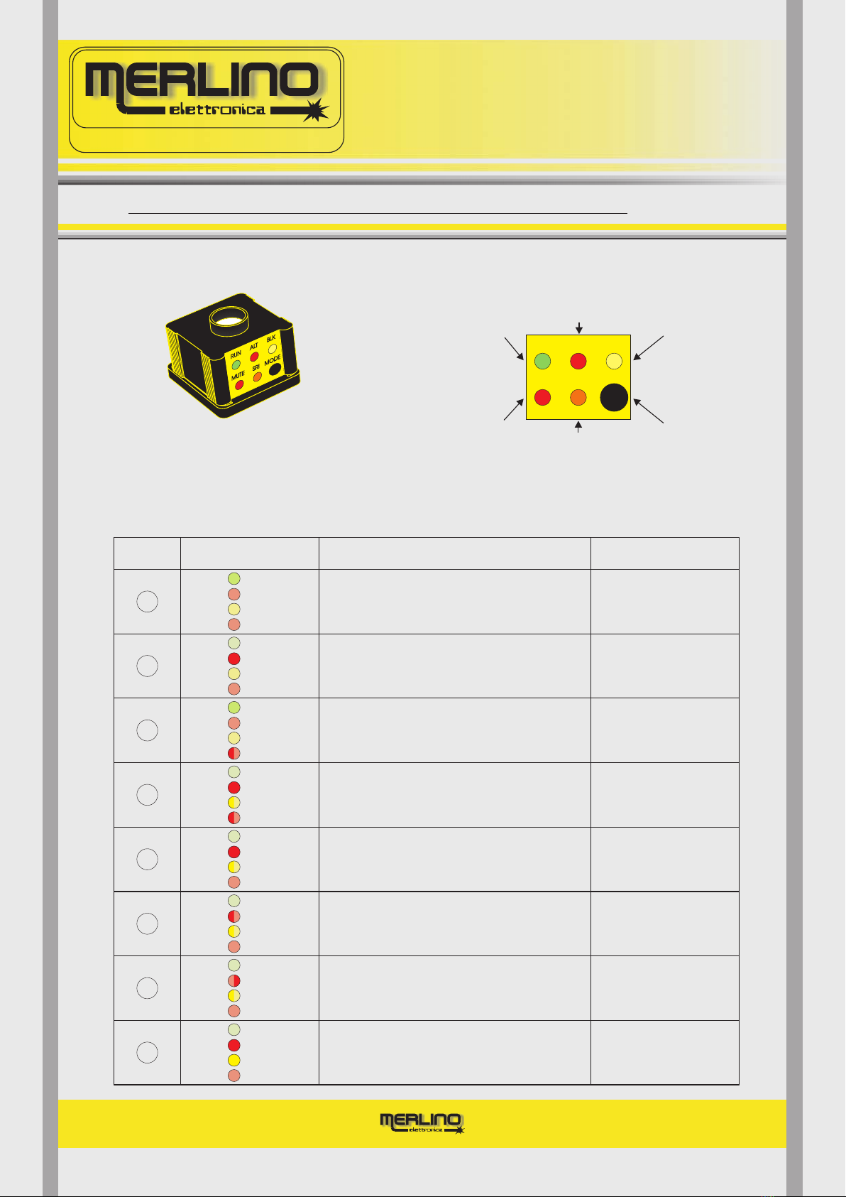
RX - TOP HEAD
MODE
SRI
MODE
function mode selector: taking of the jumper located under
the black cap the light-curtain switches from the automatic to
the manual restart operation (start/restart interlock)
manual restart operation selection indicator
(start/restart interlock), it lights on taking of the jumper
U
TROUBLESHOOTING
Fig.4
Indicates
curtain
manual
restart operation
light-
MUTE MODE
SRI
RUN BLK
ALT
Indicates aligned
with
no
light-curtain
obstacles
Indicates misaligned
light-curtain or
obstacles presence Indicates
for failure
lockout
state light-curtain
Indicates
light-curtain
muting
state
(FUTURA4 only)
Light-curtain
selector
function mode
Fig.5
CHECK AND
SOLUTION
A
Disparity between the
inside driving channels
Block briefly
the protective curtain,
if persist send to factory
Load sinking current connected
to the OSSD1 or OSSD2 higher than 0,7A,
OSSD1 or OSSD2 short-circuited to GND
(FUTURA4 model only)
FAST
SIMULTANEOUS
BLINKING
B
C
{
DEVICE STATUS
OSSD1 or OSSD2 connected to the +24Vcc
or OSSD1 short-circuited with OSSD2
(FUTURA4 model only)
OSSD1 or OSSD2 connected to the +24V
during power-on
(FUTURA4 model only)
D
LEDs STATUSCASE
BLINKING
ON
OFF
BLK
ALT
RUN
OFF
MUTE
E
F
G
H
OFF
OFF
ON
BLK
ALT
RUN
OFF
MUTE
OFF
ON
OFF
BLK
ALT
RUN
OFF
MUTE
OFF
OFF
ON
BLK
ALT
RUN
BLINKING
MUTE
BLINKING
ON
OFF
BLK
ALT
RUN
BLINKING
MUTE
ON
ON
OFF
BLK
ALT
RUN
OFF
MUTE
OFF
BLK
ALT
RUN
OFF
MUTE
OFF
BLK
ALT
RUN
OFF
MUTE
Optical alignment O.K.,
no obstacles
No failures
SLOW
ALTERNATE
BLINKING
{
No optical alignment
or obstacles presence
Possible internal fault
Improve the alignment,
remove probable obstacles.
If persist send to factory
MUTING activated, protective action
temporarely neutralized
(FUTURA4 model only)
Warning,
possible unsafe
situation
Disparity state between the
inputs, or inputs activated
with obstacles presence
MUTING Check MUTING sources,
remove probable obstacles.
If persist send to factory
Switch-off power supply,
remove the factor,
switch-on power supply
Check if the
are in the ON state
OSSDs
Remove the factor
and block briefly the
protective curtain
Remove the factor
and block briefly the
protective curtain
MISU_UK-0642 - 2.0
RATING PLATE
8
Pag. 9
PROGETTAZIONE E PRODUZIONE
APPARECCHIATURE ELETTRONICHE
MERLINO elettronica s.a.s. di Meroni N.
Via Como, 33/A - 20035 Lissone - MI
E-mail: [email protected]
Web-site: www.merlinoelettronica.it
M12 5 poles male plug M12 5 poli spina maschio
If the function TEST is not used short circuit the conductors 4-5
Se la funzione TEST non viene utilizzata cortocircuitare i conduttori 4-5
1)
2)
3) /Blu
4) /Nero
Brown
White
Blue
Black
/Marrone
/Bianco
=
= Ref.
= GND
= Test
+ 24V 5) /GrigioGrey = Test
1 2
3
4
5
M12 8 poles male plug M12 8 poli spina maschio
If the functions E.D.M. and START/RESTART are not used short circuit the conductors 3-4
Se le funzioni E.D.M. e START/RESTART non vengono utilizzate cortocircuitare i conduttori 3-4
1) /Bianco
2) /Marrone
3) /Verde
4) /Giallo
White
Brown
Green
Yellow
= SW1
= SW1
=
=}E.D.M. /
Start-Restart
5) /Grigio
6) /Rosa
7) /Blu
8) /Schermo
Grey
Pink
Blue
Shield
= SW2
= SW2
= + 24V
= GND
12
3
4
5
6
7
8
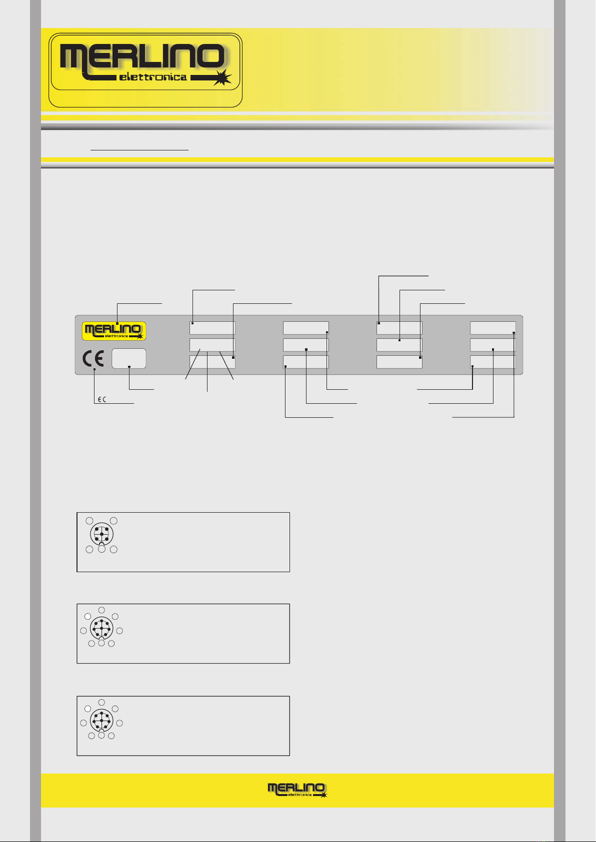
On both Transmitter (TX) and Receiver (RX) there is a label showing all the technical data
typical of the device according to the Machinery Directive 98/37/EEC Annex l° § 1.7.3
concerning safety components.
Following with reference to a specific model of light curtain called “FUTURA4/14” there is an
example of rating plate
A second label, located on the aluminium housing, shows on how to carry out electrical
connections useful for a correct use of the device.
It identified all the conductors with reference to their colouring and to the corresponding
function.
TX FUTURA
Power consumption
Progressive Num.
Month: February
Year: 2002
Protected height
Via Como 33/A LISSONE (MI) ITALY Serial number
Numero di serie
Detection capab.
Capacità di rilev.
Model
Modello
14 mm
2020001
FUTURA 4
RX Safety category
Categoria di sic.
Working range
Gamma esercizio
Protected height
Altezza protetta
TYPE 4
415 mm
PH - 6m Power consumption
Assorbimento
Response time
Tempo di risposta
40 70 mA
÷
5 - 48 ms Working temp.
Temp. esercizio
Protection degree
Grado protezione
0..+55°C
Working distance
Distanza esercizio 1200 mm
Supply voltage
Tensione aliment.
24V +/- 10%
0..+55°C
IP 65
{
{
Range
Working temperature
Protection degree
Safety category
Setting distance
Responce time
Supply voltage
Device model
Detection capability
RX FUTURA3
RX FUTURA4
1)
2)
3) /Blu
4) /Nero
Brown
White
Blue
Black
/Marrone
/Bianco
=
= Ref.
= GND
= Test
+ 24V 5) /Grigio
Grey = Test
Section
Company Logo
Marking
Fig.6
Fig.7
Fig.8
Fig.9
M12 8 poles male plug M12 8 poli spina maschio
If the functions E.D.M. and START/RESTART are not used short circuit the conductors 3-4
Se le funzioni E.D.M. e START/RESTART non vengono utilizzate cortocircuitare i conduttori 3-4
1) /Bianco
2) /Marrone
3) /Verde
4) /Giallo
White
Brown
Green
Yellow
= OUT1
= OUT2
=
=}E.D.M. /
Start-Restart
5) /Grigio
6) /Rosa
7) /Blu
8) /Schermo
Grey
Pink
Blue
Shield
= Mute1
= Mute2
= + 24V
= GND
12
3
4
5
6
7
8
1) /Bianco
2) /Marrone
3) /Verde
4) /Giallo
White
Brown
Green
Yellow
= SW1
= SW1
=
=}E.D.M. /
Start-Restart
5) /Grigio
6) /Rosa
7) /Blu
8) /Schermo
Grey
Pink
Blue
Shield
= SW2
= SW2
= + 24V
= GND
1) /Bianco
2) /Marrone
3) /Verde
4) /Giallo
White
Brown
Green
Yellow
= OUT1
= OUT2
=
=}E.D.M. /
Start-Restart
5) /Grigio
6) /Rosa
7) /Blu
8) /Schermo
Grey
Pink
Blue
Shield
= Mute1
= Mute2
= + 24V
= GND
MISU_UK-0642 - 2.0

DETERMINING THE SAFE DISTANCE
9
Pag. 10
PROGETTAZIONE E PRODUZIONE
APPARECCHIATURE ELETTRONICHE
MERLINO elettronica s.a.s. di Meroni N.
Via Como, 33/A - 20035 Lissone - MI
E-mail: [email protected]
Web-site: www.merlinoelettronica.it
To ensure the device fulfils its accident prevention functions correctly, it must be installed at a
safe distance from the point actually dangerous for the operator of the machine in such a way as
to stop the dangerous movement before that point is actually reached.
The procedure for calculating this distance is established in the harmonised European standard
EN999 which gives a number of formulas using parameters dependent on various factors
discussed below (for more detail see the standard itself).
For information only, a number of examples to calculate the installation distance from the danger
point for vertically installed light curtains with a detection capability of no more than 40 mm are
given below.
is the safe distance to be respected when installing the device
is a constant establishing the speed at which the operator approaches the danger point,
established at 2 m per second
is the time in milliseconds deriving from the sum of the time t1 taken by the machine to stop
its dangerous movement after an ALT command and the time t2 taken by the light curtain to
open the OSSDs after an obstacle has been introduced into the protected area.
is the detection capability of the in millimetres
If the result of this formula exceeds 500 mm, the value of the constant K may be reduced to 1.6 m
per second.
As is obvious, when the has a detection capability of 14 mm, the additional factor C is
zero, considerably reducing the distance in absolute value of the installation from the danger
point, in fact:
For vertically installed light curtains with a detection capability of between 40 and 70 mm, accor
ding to EN999, the formula to be used is the following:
light curtain
light curtain
For accesses protected by normally vertically installed multiple light beam device with a detec
tion capability of more than 70 mm used, the formula to be used is:
where T = t1 + t2 while C = 8 x (d 14)
C=8 x (14 14) = 0
S=KxT+C
S
K
T
d
S= 1,6x(t1+t2)+850
S= 1,6x(t1+t2)+1200
MISU_UK-0642 - 2.0

10 TECHNICAL CHARACTERISTICS - FUTURA 14 FUTURA 38
Pag. 11
PROGETTAZIONE E PRODUZIONE
APPARECCHIATURE ELETTRONICHE
MERLINO elettronica s.a.s. di Meroni N.
Via Como, 33/A - 20035 Lissone - MI
E-mail: [email protected]
Web-site: www.merlinoelettronica.it
PROTECTED HEIGHT (PH) 125 270 415 560
DETECTION CAPABILITY (DC) 14mm
WORKING RANGE
RESPONSE TIME 18 - 78msec
TX INDICATORS
OSSDs TYPES
PROTECTION FEATURES
SUPPLY VOLTAGE 24Vdc 10% on request 12Vdc±
CURRENT CONSUMPTION TX 70mA RX 50mA
WORKING TEMPERATURE 0 to +50°C
UMIDITY 25 85%÷
INTERFERENT LIGHT IMMUNITY 50.000 lux
FUTURA - 14 MODEL
PROTECTION DEGREE IP65
L= PH 5 Meters÷ H = 5 15÷ Meters
705
RX INDICATORS
TOTAL HEIGHT (TH) 195 340 485 630 775
MAX. LOAD CAPACITY 0,1 uF
WAVELENGHT = 950 nm
DISTANCE SETTING MANUAL / AUTOMATIC
OUTPUT CONNECTION
5 METERS CABLE LENGHT M12 CONNECTOR TX = 5 POLE - RX = 8 POLE
HOUSING YELLOW RAL 1021 ALUMINIUM - CROSS SECTION 41 x 46 mm
AVAILABLE FUNCTIONS
2 PNP OPEN COLLECTORS 0,7A@ 24Vdc (F4)
POLARITY INVERSION - OUTPUTS SHORT CIRCUIT - CURRENT THRESHOLD(F4) (F4)
YELLOW=LOW RANGE YELLOW=MEDIUM RANGE RED=HIGH RANGE
GREEN=ALERT RED=ALARM YELLOW=BLOCK
BLK. RED=MUTING (F4) ORANGE=MANUAL RESTART
2 VOLTAGE FREE SWITCHES 0,7A @ 40Vdc/ac
E D MXTERNAL EVICE ONITOR - START/RESTART INTERLOCK - MUTING (F4)
150
38mm
10,5 - 63msec
FUTURA - 38 MODEL
220 1739
1522
1305
1088871654
437
367 584 801 1018 1235 1452 1669
TX 70mA RX 50mA
0 to +50°C
25 85%÷
50.000 lux
IP65
0,1 uF
= 950 nm
24Vdc 10% on request 12Vdc±
L = PH 5 Meters÷ H = 5 15÷ Meters
MANUAL / AUTOMATIC
5 METERS CABLE LENGHT M12 CONNECTOR TX = 5 POLE - RX = 8 POLE
YELLOW RAL 1021 ALUMINIUM - CROSS SECTION 41 x 46 mm
2 PNP OPEN COLLECTORS 0,7A@ 24Vdc (F4)
POLARITY INVERSION - OUTPUTS SHORT CIRCUIT - CURRENT THRESHOLD(F4) (F4)
YELLOW=LOW RANGE YELLOW=MEDIUM RANGE RED=HIGH RANGE
GREEN=ALERT RED=ALARM YELLOW=BLOCK
BLK. RED=MUTING (F4) ORANGE=MANUAL RESTART
2 VOLTAGE FREE SWITCHES 0,7A @ 40Vdc/ac
E D MXTERNAL EVICE ONITOR - START/RESTART INTERLOCK - MUTING (F4)
PROTECTED HEIGHT (PH)
DETECTION CAPABILITY (DC)
WORKING RANGE
RESPONSE TIME
TX INDICATORS
OSSDs TYPES
PROTECTION FEATURES
SUPPLY VOLTAGE
CURRENT CONSUMPTION
WORKING TEMPERATURE
UMIDITY
INTERFERENT LIGHT IMMUNITY
PROTECTION DEGREE
RX INDICATORS
TOTAL HEIGHT (TH)
MAX. LOAD CAPACITY
WAVELENGHT
DISTANCE SETTING
OUTPUT CONNECTION
HOUSING
AVAILABLE FUNCTIONS
MISU_UK-0642 - 2.0

TECHNICAL CHARACTERISTICS - FUTURA 76 FUTURA 114
10.1
Pag. 12
PROGETTAZIONE E PRODUZIONE
APPARECCHIATURE ELETTRONICHE
MERLINO elettronica s.a.s. di Meroni N.
Via Como, 33/A - 20035 Lissone - MI
E-mail: [email protected]
Web-site: www.merlinoelettronica.it
295
76mm
10,5 - 33msec
FUTURA - 76 MODEL
365 799 1233 1667
729 1163 1597
TX 70mA RX 50mA
0 to +50°C
50.000 lux
IP65
0,1 uF
= 950 nm
25 85%÷
PROTECTED HEIGHT (PH)
DETECTION CAPABILITY (DC)
WORKING RANGE
RESPONSE TIME
TX INDICATORS
OSSDs TYPES
PROTECTION FEATURES
SUPPLY VOLTAGE
CURRENT CONSUMPTION
WORKING TEMPERATURE
UMIDITY
INTERFERENT LIGHT IMMUNITY
PROTECTION DEGREE
RX INDICATORS
TOTAL HEIGHT (TH)
MAX. LOAD CAPACITY
WAVELENGHT
DISTANCE SETTING
OUTPUT CONNECTION
HOUSING
AVAILABLE FUNCTIONS
24Vdc 10% on request 12Vdc±
L = PH 5 Meters÷ H = 5 15÷ Meters
MANUAL / AUTOMATIC
5 METERS CABLE LENGHT M12 CONNECTOR TX = 5 POLE - RX = 8 POLE
YELLOW RAL 1021 ALUMINIUM - CROSS SECTION 41 x 46 mm
2 PNP OPEN COLLECTORS 0,7A@ 24Vdc (F4)
POLARITY INVERSION - OUTPUTS SHORT CIRCUIT - CURRENT THRESHOLD(F4) (F4)
YELLOW=LOW RANGE YELLOW=MEDIUM RANGE RED=HIGH RANGE
GREEN=ALERT RED=ALARM YELLOW=BLOCK
BLK. RED=MUTING (F4) ORANGE=MANUAL RESTART
2 VOLTAGE FREE SWITCHES 0,7A @ 40Vdc/ac
E D MXTERNAL EVICE ONITOR - START/RESTART INTERLOCK - MUTING (F4)
657
114mm
13 - 23msec
FUTURA - 114 MODEL
727 15951161
1091 1525
TX 70mA RX 50mA
0 to +50°C
50.000 lux
IP65
0,1 uF
= 950 nm
25 85%÷
24Vdc 10% on request 12Vdc±
L = PH 5 Meters÷ H = 5 15÷ Meters
MANUAL / AUTOMATIC
5 METERS CABLE LENGHT M12 CONNECTOR TX = 5 POLE - RX = 8 POLE
YELLOW RAL 1021 ALUMINIUM - CROSS SECTION 41 x 46 mm
2 PNP OPEN COLLECTORS 0,7A@ 24Vdc (F4)
POLARITY INVERSION - OUTPUTS SHORT CIRCUIT - CURRENT THRESHOLD(F4) (F4)
YELLOW=LOW RANGE YELLOW=MEDIUM RANGE RED=HIGH RANGE
GREEN=ALERT RED=ALARM YELLOW=BLOCK
BLK. RED=MUTING (F4) ORANGE=MANUAL RESTART
2 VOLTAGE FREE SWITCHES 0,7A @ 40Vdc/ac
E D MXTERNAL EVICE ONITOR - START/RESTART INTERLOCK - MUTING (F4)
PROTECTED HEIGHT (PH)
DETECTION CAPABILITY (DC)
WORKING RANGE
RESPONSE TIME
TX INDICATORS
OSSDs TYPES
PROTECTION FEATURES
SUPPLY VOLTAGE
CURRENT CONSUMPTION
WORKING TEMPERATURE
UMIDITY
INTERFERENT LIGHT IMMUNITY
PROTECTION DEGREE
RX INDICATORS
TOTAL HEIGHT (TH)
MAX. LOAD CAPACITY
WAVELENGHT
DISTANCE SETTING
OUTPUT CONNECTION
HOUSING
AVAILABLE FUNCTIONS
MISU_UK-0642 - 2.0

ELECTRICAL CONNECTIONS
11
Pag. 13
PROGETTAZIONE E PRODUZIONE
APPARECCHIATURE ELETTRONICHE
MERLINO elettronica s.a.s. di Meroni N.
Via Como, 33/A - 20035 Lissone - MI
E-mail: [email protected]
Web-site: www.merlinoelettronica.it
RXTX
5
12
34
12
3
4
5
6
7
8
1
2
3
4
5
6
7
8
1) Brown
2) White
3) Blue
4) Black
5) Grey
= + 24V
= Ref.
= GND
= Test
= Test
1) White
2) Brown
3) Green
4) Yellow
5) Grey
6) Pink
7) Blue
8) Red
Shield
= OSSD1................. SW1
= OSSD2 SW1
=
=
= MUTE1 SW2
= MUTE2 SW2
= + 24V
= GND
................
.................
.................
= GND
}E.D.M./
Start-Restart
FUTURA3
1 2
3
5
4
Male plug
5 CONDUCTORS M12
FEMALE CONNECTOR
Female socket Female socket
Male plug
If the function TEST is not used, short
circuit the conductors 4 5 and connect
them to the “0V” of power supply blue (3)
If the functions E.D.M. and START RESTART
are not used, short circuit the conductors
3 4 and connect them to the “0V” of power
supply red/shield (8)
3
2
1POWER SUPPLY
24Vdc +/- 10%
BROWN
BLUE
BLACK
WHITE
GREY
5
4
TEST INPUT
NORMALLY CLOSED
CONTACT
Jumper
If the function TEST is not used, short
circuit the conductors 4 5 and connect
them to the “0V” of power supply blue (3) 5m standard
cable length
Reference voltage (useful for testing)
connect it to the “0V” of power supply blue (3)
TX FUTURA
5 conductors cable
8 CONDUCTORS M12
FEMALE CONNECTOR
5 CONDUCTORS M12
FEMALE CONNECTOR
Fig.10 Fig.11
Fig.12
+24V
0V
MISU_UK-0642 - 2.0

ELECTRICAL CONNECTIONS - RX
11.1
Pag. 14
PROGETTAZIONE E PRODUZIONE
APPARECCHIATURE ELETTRONICHE
MERLINO elettronica s.a.s. di Meroni N.
Via Como, 33/A - 20035 Lissone - MI
E-mail: [email protected]
Web-site: www.merlinoelettronica.it
D1
D2
K1
K2
RX FUTURA4
8 conductors shielded cable
RX FUTURA3
8 conductors shielded cable
5
6
BROWN
WHITE
PINK
YELLOW
GREY
GREEN
2
1
SW1
SW2
SW1
SW2
Imax = 0,7A
Imax = 0,7A
Vmax = 40Vdc/ac
Vmax = 40Vdc/ac
5m standard
cable length
F1
F2
F1=F2= fuses of a higher value
than the current sinking
into the load (suggested)
Fig.13
D1=D2= rectifier diodes to suppress
“spike” generated by the an
inductive load that reduced
life of the output switches of
the light-curtain (recommended)
8 CONDUCTORS M12
FEMALE CONNECTOR
SCR = extra-voltages discharger to
suppress possible high energy
discharge (recommended)
5
6
BROWN
WHITE
PINK
YELLOW
GREY
GREEN
D1
2
1
3
4
D2
E D Mxternal evice onitor
K2
I =max 0,7A
K1
OSSD1
MUTE1
Control devices of the MUTING function.
: when activated, temporarely, they
neutralize the light-curtain protective action.
WARNING
OSSD2
Jumper
MUTE2
5m standard
cable length
8 CONDUCTORS M12
FEMALE CONNECTOR
F1F2
Fig.14
If the functions E.D.M. and START-RESTART
are not used, short circuit the conductors
3-4 and connect them to the “0V” of power
supply red/shield (8)
P.N. : the E.D.M. function works
only if loads K1, K2, … Kn are
with forced interlocked contacts
operation. E.D.M. must be used to
reach the safety caegory declared.
I =max 0,7A
INTERLOCK
PUSH-BUTTON
START/RESTART
F1=F2= fuses of a higher value
than the current sinking
into the load (suggested)
D1=D2= rectifier diodes to suppress
“spike” generated by the an
inductive load that reduced
life of the output switches of
the light-curtain (recommended)
+24V POWER SUPPLY
24Vdc +/- 10%
SCR
SCR = extra-voltages discharger to
suppress possible high energy
discharge (recommended)
P.N. : if the sinking current is less than
100mA than connect the load to the
conductor, if it is higher to
the “0V” of power supply
green (3)
red/shield (8)
NC SWITCH
K1
NC SWITCH
K2
NC SWITCH
Kn
3
4
E D Mxternal evice onitor
Jumper
If the functions E.D.M. and START-RESTART
are not used, short circuit the conductors
3-4 and connect them to the “0V” of power
supply red/shield (8)
INTERLOCK
PUSH-BUTTON
START/RESTART
NC SWITCH
K1
NC SWITCH
K2
NC SWITCH
Kn
0V
+24V POWER SUPPLY
24Vdc +/- 10%
SCR
0V
P.N. : the E.D.M. function works
only if loads K1, K2, … Kn are
with forced interlocked contacts
operation. E.D.M. must be used to
reach the safety caegory declared.
BLUE
SHIELD
RED
7
8
{
7
8
BLUE
RED
SHIELD
{
MISU_UK-0642 - 2.0

MECHANICAL DATA
12
Pag. 15
PROGETTAZIONE E PRODUZIONE
APPARECCHIATURE ELETTRONICHE
MERLINO elettronica s.a.s. di Meroni N.
Via Como, 33/A - 20035 Lissone - MI
E-mail: [email protected]
Web-site: www.merlinoelettronica.it
14
3
20
16
24
1,5
1
18
2
7
8,5 1,5
0,5
1,5 1,5
44
6,5 3,5 3,5
41
6,5
15,5
3
5,5
TOP HEAD
SECTION VIEW
3
20
24
1,5
6
2
7
8,5 1,5
0,5
1,5 1,5
44
41
13,5
3
Fig.15
Fig.16
Fig.17
Fig.18
7
13
4MA
15
46
41
15
HOUSING CROSS
SECTION
41x46
Osmall
shock absorbing cylinders
ptional
O second
frontal black filter
ptional
Tighten the hexagonal
head screw to block
Tighten the hexagonal
head screw to block
H
BOTTOM HEAD
SECTION VIEW
HOUSING CROSS
SECTION VIEW
MISU_UK-0642 - 2.0

MAINTENANCE AND CONTROLS
13
Pag. 16
PROGETTAZIONE E PRODUZIONE
APPARECCHIATURE ELETTRONICHE
MERLINO elettronica s.a.s. di Meroni N.
Via Como, 33/A - 20035 Lissone - MI
E-mail: [email protected]
Web-site: www.merlinoelettronica.it
The transmitter and receiver units require no particular maintenance. However, the black front
screens protecting the optics should be cleaned daily to remove large quantities of dust.
Avoid rubbing the screens with abrasive cloths as rubbing causes static electricity and attracts
dust. To clean, use alcohol. Avoid plastic solvents.
When the device is used for the first time, to guarantee safe conditions, the correct setting of the
functions must be controlled. When using the device for the first time, operation of the device in
the particular application must first be verified. This must be done by specialist personnel. Acci
dent prevention legislation specifies that this control should be performed daily.
Before beginning any form of work, it is good practice to verify that:
with the machine stationary and power to the on (no obstacle in the protected
area), the green indicator is lit.
with the machine stationary and power to the on in the presence of an obsta
cle in the protected area, the red indicator is lit.
moving parts are not accessible to personnel. Any extraordinary maintenance must
therefore be carried out under the strict supervision of the safety manager. All accesses
not pro tected by electro sensitive protective devices must be equipped with fixed material
barriers or other.
A sheet indicating the daily checks must be compiled by the operator of the machine and must
be clearly visible near the workstation.
DAILYCONTROLSANDPERIODICALTESTS
RUN
ALT
light curtain
light curtain
with the machine running, introduction of the test piece at any point in the protected area
switches the green indicator to the red indicator, shutting down the machine within the
specified time.
The "FUTURA" invisible optoelectronic active infrared light curtain consists of the following ele
ments, provided on request as spare parts:
M12 5 pole output connector for TX with 5 m long cable....................
M12 8 pole output connector for RX with 5 m long cable..................
Manual with duplicate of the “ DECLARATION OF CONFORMITY
Adjustable brackets for installing the TX and RX ............................
ALT
MATERIALSUPPLIEDASSPAREPARTS
a)
b)
d)
c)
code
....... CON M12 5P 5M
......... CON M12 8P 5M
”........... MISU FUTURA
......... SSO 49 28,5
MISU_UK-0642 - 2.0

HOW TO ORDER
14
Pag. 17
PROGETTAZIONE E PRODUZIONE
APPARECCHIATURE ELETTRONICHE
MERLINO elettronica s.a.s. di Meroni N.
Via Como, 33/A - 20035 Lissone - MI
E-mail: [email protected]
Web-site: www.merlinoelettronica.it
REFERENCE CODE FOR ORDERING
All models of the "FUTURA" active infrared light curtains are calibrated during
factory testing according to the specified by the customer in the last part of
the order code. Should it be necessary to modify this distance at a later date, you should
contact the manufacturer who will modify the calibration for the new working distance.
Alternatively, contact the factory telephonically for instructions on how to proceed. For all
those models ordered with the optional function of
(AUTO), calibration takes place completely automatically for the specific distance concerned
each time power to the device is turned on.
optoelectronic
working distance
automatic working distance calibration
Below are a number of examples of order codes (with relative comments) for different models of
the "FUTURA" optoelectronic light curtains.
model designed to protect from risks up to category 3 ac
cording to EN954 1, with a maximum detection capabi
lity of 76 mm, protected height of 729 mm and range of
between 5 and 15 m.
Calibrated working distance 7,5 m.
model designed to protect from risks up to category 4 ac
cording to EN954 1, with a maximum detection capabi
lity of 14 mm, protected height of 560 mm and range of
between 560 and 5000 mm.
Calibrated working distance 900 mm.
model designed to protect from risks up to ca
tegory 4 according to EN954 1, with a maxi
mum protection capability of 38 mm and pro
tected height of 801 mm, with automatic cali
bration for a distance of between 801 and
5000 mm.
.
FUTURA3/76 - PH729/H/7,5
FUTURA4/14 - PH560/L/900
FUTURA4/38/AUTO - PH801/L
Automatic calibration
SAFETY CATEGORY ( )3 OR 4
RANGE
PROTECTED HEIGHT
(mm)
H5÷15m
AUTOMATIC CALIBRATION
WORKING DISTANCE
AUTO LPH÷5m
FUTURA / / - PH / /
DETECTION CAPABILITY (mm)
(14 - 38 - 76 - 114)
Optional WORKING DISTANCE
(m)
(mm)
Fig.19
MISU_UK-0642 - 2.0
This manual suits for next models
6
Table of contents
Other Merlino Safety Equipment manuals

Popular Safety Equipment manuals by other brands

Trinity Highway
Trinity Highway QuadGuard Elite M10 Product Description Assembly Manual

Syntech
Syntech MAXAIR CAPR 2272PB-100 User instructions

KidKusion
KidKusion 4680 instructions

Metacon-Next
Metacon-Next FirePro V4 user manual

Guardian Fall Protection
Guardian Fall Protection Cable LE Lanyard instruction manual

Harken
Harken SNATCHET INSN65R manual


