Metacon-Next FirePro V4 User manual

User manual
FirePro V4
Type: HW V4.4 SW V5.2
Version: 20220628
PLEASE CAREFULLY REA THIS USER MANUAL BEFORE YOU USE
THE CONTROLLER.
STORE THIS INFORMATION SO THAT IT CAN BE REFERENCE IN
THE FUTURE!

2
© 2022 RDA-BV.
This manual is translated from the original Dutch manual, In the e ent of discrepancies between the two, the
Dutch ersion shall pre ail.
Subject to changes and typing errors.
The information in this manual is subject to change and can be re ised if necessary. No rights can be claimed
from the pro ided information.
All rights reser ed. All mentioned trademarks are the property of their respecti e owners.
No part of this publication can be reproduced and/or disclosed by way of printing, photocopy, microfilm or any
other means whatsoe er without recei ing written consent from RDA-BV..
RDA-BV.
Spoorakkerweg 6 info@rda-b .nl
5071 NC Udenhout www.rda-b .nl
Item no. : 714487.000001

3
Foreword
1. Foreword
This manual is intended as a guide when using the FirePro controller in combination with a “Fail-safe”
dri e unit type FS by GFA Elektromaten.
We would like to thank you for working with us, and for the trust that you ha e placed in our
product.
2. Using the manual
Before using the controller, it is mandatory to read this user manual and to ha e in depth knowledge
of the information in this user manual. All actions on the controller must be carried out as described
in the user manual.
This user manual is an integral part of the controller and must, as prescribed by applicable legislation,
be retained for reference purposes until the controller is disposed of.
Make sure that this user manual is within reaching distance of people who come into contact with
the controller. Ensure a place that is safe, dry and shielded from the sun.
If the manual is damaged, a new copy must be requested form RDA-BV..
3. Target group
This user manual is intended for users as well as installation engineers, and addresses use,
maintenance and testing procedures relating to this controller and the connected dri e unit. Users
must be suitably trained to operate and/or test this controller in combination with the connected
door, and may not perform acti ities on the controller under any circumstances.
4. Used symbols
The following symbols ha e been used in this user manual:

4
TIP
Gi es the user suggestions or ad ice that make a procedure easier or more practical to execute.
COMMENT
A general comment that possibly offers extra economic benefits.
ENVIRONMENT
Guidelines that must be followed when using hazardous substances and when recycling products
and materials.
CAUTION
Indicates a dangerous situation that, if safety-related instructions are not followed, could result in
a minor to moderate injury and/or damage to the controller or the surroundings.
WARNING
Indicates a dangerous situation that, if safety-related instructions are not followed, could lead to a
serious or fatal injury and/or damage to the controller or the surroundings.
ANGER
Indicates a dangerous situation that, if safety-related instructions are not followed, will lead to a
serious or fatal injury.

5
Contents
Foreword .......................................................................................................................... 3
1. Foreword ................................................................................................................................. 3
2. Using the manual .................................................................................................................... 3
3. Target group ............................................................................................................................ 3
4. Used symbols .......................................................................................................................... 3
Contents ........................................................................................................................... 5
1
Introduction ............................................................................................................... 8
1.1 Intended use............................................................................................................................ 8
1.2 Forbidden use .......................................................................................................................... 8
1.3 Life span of batteries ............................................................................................................... 9
1.4 Type designation ..................................................................................................................... 9
1.5 Technical details .................................................................................................................... 10
2
escription ............................................................................................................... 11
2.1 Front iew.............................................................................................................................. 11
2.2 Internal iew .......................................................................................................................... 12
2.3 Description of controller ....................................................................................................... 13
3
Functioning .............................................................................................................. 14
3.1 Functioning ............................................................................................................................ 14
4
Safety ....................................................................................................................... 17
4.1 Safety systems ....................................................................................................................... 17
4.2 Safety arrangements ............................................................................................................. 17
4.3 Specific safety guidelines ...................................................................................................... 17
4.4 Meaning of warning signals .................................................................................................. 18
4.5 Signs and symbols ................................................................................................................. 19
5
Transport and storage .............................................................................................. 20
5.1 Transporting the de ice ........................................................................................................ 20
5.2 Storing the de ice for a long period ...................................................................................... 20
6
Assembly and installation ......................................................................................... 21
7
Commissioning ......................................................................................................... 23
7.1 Commissioning ...................................................................................................................... 25
7.2 Configuring end switches (NES) ............................................................................................ 25
7.3 Configure “o er-close NES position” ..................................................................................... 26
7.4 Runtime NES dri e unit ......................................................................................................... 26
7.5 Configuring end switches DES ............................................................................................... 27
7.6 Configure “o er-close DES position” ..................................................................................... 27
8
Connection ............................................................................................................... 28
8.1 Terminal connections ............................................................................................................ 28

6
1.
Mains power .............................................................................................................................. 28
2.
Brake .......................................................................................................................................... 28
3.
Brake interruption ..................................................................................................................... 28
4.
Potential-free contacts .............................................................................................................. 29
5.
Programmable input .................................................................................................................. 29
6.
Photocell .................................................................................................................................... 29
7.
PNP light curtain ........................................................................................................................ 30
8.
Pass door / Slack cable / cable breakage X12 ............................................................................ 30
9.
Safety edge ................................................................................................................................ 30
10.
OSE light curtain ........................................................................................................................ 31
11.
External controls ........................................................................................................................ 31
12.
Inputs ......................................................................................................................................... 31
13.
Fire alarm input ......................................................................................................................... 32
14.
Safety brake ............................................................................................................................... 32
15.
Dri e unit ................................................................................................................................... 32
16.
Control panel ............................................................................................................................. 33
17.
RJ 45 connector ......................................................................................................................... 33
18.
DES / NES ................................................................................................................................... 33
8.2 Control cable FirePro V4 ........................................................................................................ 34
8.3 Operating instructions ........................................................................................................... 35
8.4 Parameter series 0, basic settings ......................................................................................... 36
8.5 Parameter series 1, (end) position settings ........................................................................... 38
8.6 Parameter series 2, action settings ....................................................................................... 39
8.7 Parameter series 3, emergency settings ............................................................................... 40
8.8 Parameter series 4, warning settings .................................................................................... 41
8.9 Parameter series 5, output settings ...................................................................................... 43
8.10 Parameter series 8, maintenance settings ............................................................................ 45
8.11 Parameter series 9, registration ............................................................................................ 45
9
(Error) Messages ...................................................................................................... 46
9.1 Status messages .................................................................................................................... 46
9.2 Error messages (for questions: +31 (0) 182 23 15 25 or ser ice@metacon-next.com) ........ 46
10
Configuration fire/smoke detector ........................................................................... 50
10.1 FD (fire detection) function (alarm/emergency) ................................................................... 50
10.2 Continue running if battery empty (only for digital end switch DES) ................................... 50
10.3 Maintenance counter ............................................................................................................ 51
10.4 Smoke gasket ......................................................................................................................... 51
11
Maintenance ............................................................................................................ 52
11.1 Pre enti e maintenance ........................................................................................................ 52
11.1.1
Maintenance plan ...................................................................................................................... 52
11.1.2
Maintenance instructions .......................................................................................................... 53
11.1.3
Cleaning the de ice ................................................................................................................... 53
12
ecommissioning and disposal ................................................................................. 54
12.1 Decommissioning .................................................................................................................. 54
12.2 Disposal.................................................................................................................................. 54
Appendices ..................................................................................................................... 55
5. EC declaration or Declaration of incorporation..................................................................... 55

7
6. Spare parts ............................................................................................................................ 57
7. Installation details (to be filled in by the installation engineer) ........................................... 58
8. Maintenance sheet ............................................................................................................... 59

8
1Introduction
1.1 Intended use
Safe use of this controller can only be guaranteed if it is used for its intended purpose. The
manufacturer is not responsible for damage that is caused by external components or failure to
comply with these instructions.
-Modifications are only permitted in consultation with the manufacturer. The manufacturer’s
declaration of conformity will no longer be alid if modifications are made without recei ing
consent from the manufacturer.
-When installing, commissioning, maintaining and inspecting the controller, the safety and
accident-pre ention guidelines that apply to the specific project must be respected.
-Only qualified personnel, who possess the required equipment and knowledge, are
permitted to perform acti ities on this controller. ‘Qualified personnel’ can be interpreted as:
people who are familiar with the installation, configuration, commissioning and operation of
electric door and gate installations. They must be capable of e aluating the whole
installation, recognizing potential dangers, and installing the required safety features.
-Suitable and appro ed tools must be used when installing, commissioning, maintaining and
inspecting the controller.
-The controller must be installed in the immediate icinity of the door that is to be operated.
A good iew of the door opening must be guaranteed when doing so.
-Only use safety products that comply with the applicable norms. Examples include: safety
edges, photocells, smoke detectors and heat detectors.
-People who do not possess enough experience cannot use this de ice unless they are being
super ised or ha e recei ed instructions about how the de ice can be used in a safe manner,
and understand the accompanying risks.
-Pay special attention to pre enting risks that could lead to injury if people become crushed
between components that are operated by the automated system and the stationary
surrounding components; children must be super ised to ensure that they do not play with
the equipment. The controller cannot be used for mo ing parts with a pass door, unless it
can only be operated when the pass door is in safety mode.
If used for other purposes, please contact the supplier.
1.2 Forbidden use
The manufacturer accepts no liability for damage that has been caused by operation and connection
errors, failure to comply with the user manual or sub-standard maintenance and/or ser ice, and once
again draws attention to dangerous situations that could be encountered as a result. Despite

9
conformity with harmonized standards, it is not possible to foresee all dangers. That is why people
should only enter the danger zone if this is truly necessary. If there are doubts about the installation,
do not continue and contact the supplier for clarification.
All information in this document (photos, drawings, characteristics and dimensions) may be subject
to change without prior notification.
It is forbidden to connect components to the controller which ha e not been appro ed by the
manufacturer.
They could:
hinder the performance of the controller;
endanger the safety of the user or other people;
reduce the life span of the controller;
nullify compliance with CE guidelines.
It is forbidden to use the controller for a purpose other than the intended use. Failure to comply with
the intended use could endanger the safety of the user or other people.
1.3 Life span of batteries
The life span of batteries used in this controller is ca. 2 years if installed in an en ironment of ca.
20°C. En ironment temperatures abo e 40°C or below 5°C during use or abo e 40°C or below -15°C
during storage can ha e an impact on the life span and/or correct operation of the batteries. We
recommend replacing the batteries e ery year.
1.4 Type designation
Figure 1 Example of the type plate
10
Figure 2 Position of the type plate
1.5 Te hni al details
Ta le1 Technical details
ata
Explanation
Weight 10 kg
Height 400 mm
Width 300 mm
Depth 150 mm
Electricity consumption Max. 2.2 kW
Power 3N~400Vac +/- 10%, 50/60 Hz
3~230Vac +/- 10%, 50/60 Hz
1N~230Vac +/-10%, 50/60 Hz
Fuse Max. 6.3 A slow
Motor capacity Max. 2.2 kW
Electricity Max. 8,3 A
Brake 24 Vdc
Control oltage 24 Vdc
Control current 300 mA
External power 24 Vdc
Current external power Max 500 mA
Relay outputs potential-free changeo er switches
Load of relay contacts Max. Ohm load = 1 A / Max. inducti e load = 1 A
Battery Voltage : 12 Vdc
Capacity : 5.2 Ah
LxWxH : 90 x70 x 106 mm
Brand : CSB battery
Type : HR1221W
Weight : 1.8 Kg
Technology : AGM
Protection class IP 40
En ironment temperature +5...+40°C
Relati e humidity Max. 93% (non-condensing)
Vibration Install ibration-free (e.g. brick wall)

11
2escription
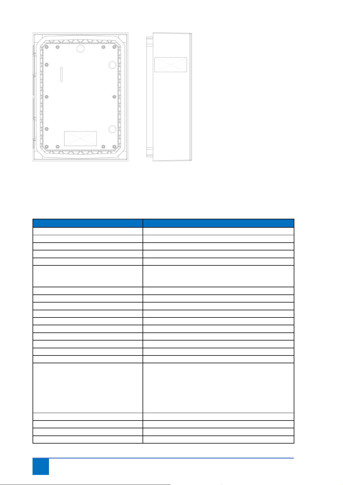
2.1 Front view
Figure 3 Front view
Ta le 2 Layout front view
No.
Component
1
Casing
2
Signal transmitter
3
Front
panel
4
Cable inlet 4 x M16
5
Ventilation
6
Lock
7
Cable inlet 2 x M20
12
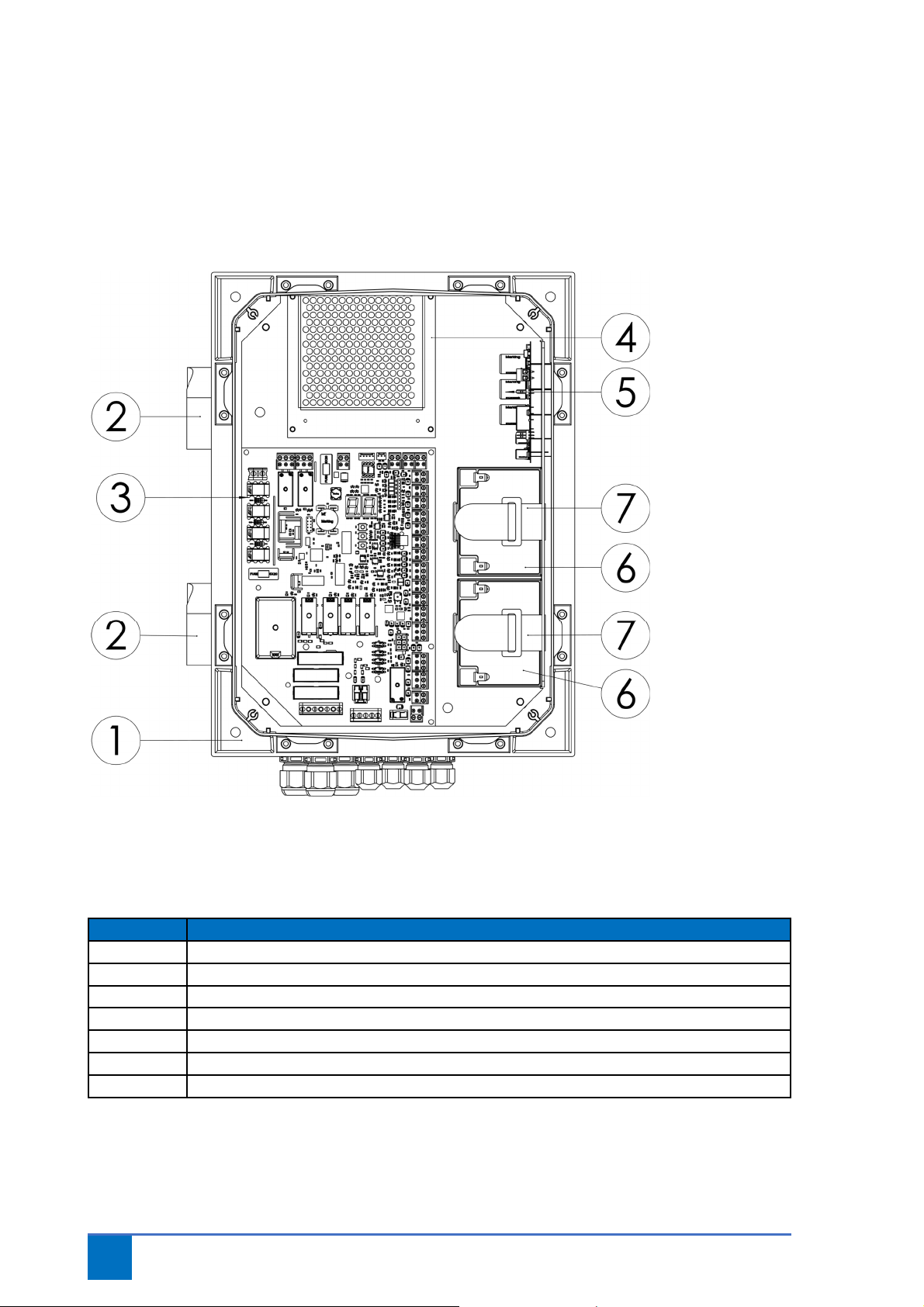
2.2 Internal view
The FirePro includes a cabinet containing a control circuit board in combination with
power/charger and 2 batteries (12V-5.2Ah). The lid of the cabinet has a control panel that
features 4 status LEDs.
Figure 4 Internal view
Ta le 3 Layout internal view
No.
Component
1
Casing
2
Ventilation
3
FirePro V4 control circuit board
4
Power/charger
5
Signal transmitter board (P
-
CAP)
6
Battery
7
Battery attachment

13
WARNING
Only use accessories that comply with the applicable standards.
2.3 Des ription of ontroller
The FirePro is a controller for ertically-operating fire and/or smoke-proof doors (for example,
shutter sectional doors and fire hatches) that feature a FailSafe dri e unit (FS series) by GfA-
Elektromaten.
This controller is part of an electrically-powered fireproof door, and uses its own energy - in this case,
based on gra ity - to close the door in the e ent of a fire.
The FirePro includes a cabinet containing a control circuit board in combination with power/charger
and 2 batteries (12V-5Ah).
Characteristics of this controller:
-Hold to run or automatic operation
-Operation ia panel on cabinet lid or external controls
-Status display ia 4 LEDs on cabinet lid
-Buzzer with mute function
-Fire alarm input
-Smoke and heat alarm input
-Input for safety edge
-Input for security contacts (safety brake, pass door/slack cable contact)
-Input for sensor operation
-Input for escape button
-2 potential-free programmable switch contacts
-Output for signal transmitter
In case of fire alarm, loss of power or empty batteries, the door will lower because power to the
electric brake is cut (if this has been selected in the menu). If mains power is still present, the door
will lower until the ‘close’ end switch or the “o er close” end switch has been reached. Once the fire
alarm returns to normal, the door will be released immediately (par.5.3), after a certain period of
time (par.3.4) or can be reset (par.4.6).

14
3Functioning
3.1 Fun tioning
The FirePro co ers a cabinet with a control circuit board in combination with a power
supply/charger.
This controller can operate as “hold to run” as well as automatically when in normal mode.
-Operation in normal mode is possible using the buttons on the cabinet and/or the external
up, stop and down controls. An input is also a ailable for sensor-based operation (e.g. pull
switch).
-The lid features 4 LEDs for showing the status of the controller (see table 7).
-An input is a ailable for the safety contact (NC) and safety brake; this input is a stop function.
There is also an input for cable breakage protection and/or a pass door contact; this is an NC
contact in series with a 5.1kΩ +/-10% resistor. The controller can be attached to batteries so
that the control will continue to operate effecti ely in case of power failure, until the
batteries are almost empty.
WARNING
Upon deli ery, the + side of the batteries will be disconnected in order to pre ent drainage!
Make sure that the batteries ne er become completely empty; this can be caused if the controller
is not connected to mains power for a long period of time. The batteries cannot be re-used if they
become completely empty. In this case, replace the batteries. Disconnect the battery connection if
the door is in a safe position.
WARNING
If the dri e unit has mechanical limit switches, an interim stop is only possible if the “o er-close”
function is not being used.
-In case of fire alarm, the ‘close in case of power loss’ option or empty batteries, the door will
lower because power to the electric brake will be cut. If power is still present, the door will
lower until the ‘close’ end switch or the “o er close” end switch has been reached.
PLEASE NOTE: in case of digital end switches (DES), there must be effecti e communication between
the end switch and the controller!
WARNING
The doors will close automatically if the fire contact is acti ated, in case of power failure or if the
batteries are almost empty (and the “close” option has been selected in this case). PLEASE NOTE:
this mo ement can be performed without the safety feature!
-
The menu can be used to configure whether the door, if closing for safety reasons, will lower
until the normal end switch or until the “o er-close” end switch has been reached. The
“o er-close” end switch makes it possible to close the door further than it would close during
normal operation. It is also possible to make an interim stop, for a configured time, when
closing in case of a fire, in case of power failure or in case of low battery oltage.
15
-In case of a fire alarm, the door will be released immediately or after an extended period of
time.
-There are two fire alarm inputs. The menu can be used to decide whether or not they must
be reset so that the door is restored to normal operating mode. If a fire alarm input must be
reset, a time delay can be selected for releasing the door. This means the door will only
operate normally after the configured period of time.
-It also possible to select whether escape is possible or not when the door is completely
closed at a desired fire alarm input. A decision can also be made about whether the contact,
which indicates that the door is closed, will be switched on if the door has closed after the
fire alarm input was acti ated.
WARNING
Once a fire alarm has been acti ated, escape will no longer be possible if the door is fully closed.
That is why, in accordance with existing legislation, a separate escape route must be a ailable.
-There are two inputs that can be configured ia the menu. These inputs ha e arious
functions, as described in the menu-related explanation in this user manual.
-A P-CAP signal transmitter is installed in the casing. This will issue a signal if an error message
becomes acti e. If the “mute” button is pressed on the lid, this will be stopped until a new
message becomes acti e. The “mute” button will not work if the door closes during
emergencies.
-An output is present for connecting an extra signal transmitter.
-It is possible to connect a safety edge. This can be done using a safety feature with potential-
free relay contact (N.C.) in combination with a 1.2KΩ resistor that features an air pressure
switch/dw contact. Or ia an electric pressure frame with an 8.2KΩ resistor or opto sensors.
WARNING
If a safety edge is used, the door must be inspected to confirm that it complies with applicable
standards. If a safety feature with a relay contact (potential-free NC contact) is used, a 1.2KΩ
resistor must be connected in series within this safety feature. In this case, a test must also carried
be out on the DW/air pressure switch.
-During normal operation, the safety edge will only work if self-hold closing has been
selected. During closure in case of fire alarm, low battery oltage or power failure (if
batteries are present and ha e enough capacity), the software can be used to switch the
safety edge on or off as preferred. If the safety edge has been acti ated, the door will stop
descending when the safety edge is triggered. The programming menu can be used to select
the preferred safety feature, and it is possible to configure the time that the door will wait
(when a safety feature is triggered) before continuing to descend. If mains power is still
present, one can also decide to open the door completely and then close once again. In this
case, the door will stop and fully open again. The same can be done when acti ating the
photocell safety feature.
WARNING

16
If the safety edge or photocell safety feature is acti ated in case of closure during a fire alarm,
power failure or almost empty battery, the controller will regard the concerned safety feature to
be faulty if it is acti ated continuously for 120 seconds (factory setting) or longer, and the door
will then continue closing without the safety feature!
-It is possible to connect an escape button, whereby the door can be opened in case of a fire
alarm (if mains power is still present), to allow someone to escape. The door will close again
after a configured time. There is also a setting that allows the door to be opened again with
the open button if mains power is a ailable. The door will close again when the button is
released.
-Parameter 8.5 in the menu can be used to acti ate a maintenance cycle. The LED will flash
red and green alternately if this has been acti ated and the number of configured cycles has
been reached. A message will appear on the display. Parameter 8.7 can also be used to close
the door once the number of configured mo ements has been reached.
17
4Safety
4.1 Safety systems
Only use safety products that comply with the applicable norms.
Examples include: safety edges, photocells, smoke detectors and heat detectors.
4.2 Safety arrangements
Only qualified personnel, who possess the required equipment and knowledge, are permitted to
perform acti ities on this controller. ‘Qualified personnel’ can be interpreted as: people who are
familiar with the installation, configuration, commissioning and operation of electric door and gate
installations. They must be capable of e aluating the whole installation, recognizing potential
dangers, and installing the required safety features.
This controller is a component within a machine. Make sure that e ery component used in the
installation is suitable for the intended system as a whole.
Do not continue with the installation if one of the components is not suitable!
Perform a risk analysis, which includes a list of essential safety guidelines as prescribed in Appendix I
of the Machinery Directi e, where the implemented solutions are mentioned. The risk analysis is one
of the documents that is included in the technical dossier of the electrically powered door. This must
be compiled by a professional installation engineer.
4.3 Spe ifi safety guidelines
Safe use of this controller can only be guaranteed if it is used for its intended purpose. The
manufacturer is not responsible for damage that is caused by external components or failure to
comply with these instructions.
Modifications are only permitted in consultation with the manufacturer. The manufacturer’s
declaration of conformity will no longer be alid if modifications are made without recei ing consent
from the manufacturer.
When installing, commissioning, maintaining and inspecting the controller,
safety and accident-pre ention guidelines that apply to the specific project must be
taken into consideration.
Suitable and appro ed tools must be used when installing, commissioning, maintaining and
inspecting the controller. Before starting acti ities on this controller, the door must be placed in a
safe position, the mains power must be cut and the poles of the batteries must be disconnected.
WARNING
Performing acti ities on the controller while it is still being powered is perilous and can cause
serious injury!
WARNING
Only use the controller for the purpose for which it was designed. See 1.1 Intended use on page
8.

18
WARNING
The controller can only be managed by people who ha e read the user manual and are thus
sufficiently familiar with the functioning, operation, maintenance, etc. of the controller, as
described in this user manual.
ANGER
It is forbidden to remo e, bypass or deacti ate safety features and protecti e de ices.
CAUTION
Make sure that all safety features are correctly acti ated again after all maintenance acti ities and
other inter entions.
ENVIRONMENT
Comply with local legal requirements for all products that are used in the controller and for all
products used to maintain and clean the controller.
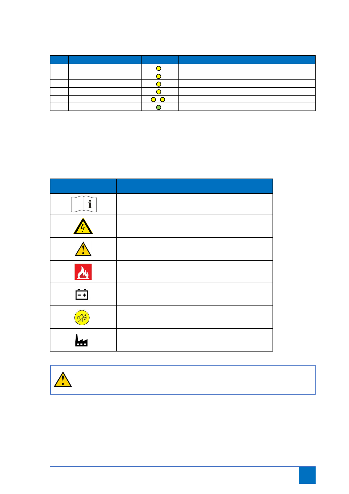
4.4 Meaning of warning signals
Ta le 4 Warning signals control panel
No.
Warning signal
Symbol
Meaning
1 Green LED
LED on: Mains power present
LED flashing: Maintenance cycle reached
1 Red LED
LED on: Error message acti e
2 Red LED
LED on: Emergency acti e
3 Red LED
LED on: Battery error
4 Mute button
Switch off buzzer
5 Signal transmitter
See Parameter 5.5
19
Ta le 5 Warning signals power/charger.
4.5 Signs and symbols
Ta le 6 Signs and sym ols
Pictogram
Explanation
4
Please carefully read the manual before using this de ice.
Risk of electrocution
Low oltage – 230/400 V ac
Warning
Possible injury or danger
Emergency
Battery
Switch off buzzer
Factory setting
CAUTION
Make sure that the pictograms are isible at all times. Clean the pictograms on a regular basis and
replace them in case of wear and tear.
No.
Warning signal
Symbol
Meaning
1 Mains fail
LED on: No mains power
1 Batt Low
LED on: Low battery oltage
2 Batt O/C
LED on: No battery present
3 Charger loss
LED on: Error message charger
4 Batt O/C + Batt. low
LED on: High impedance batteries (replace batteries)
5 Status
LED flashing: charger OK

20
5Transport and storage
5.1 Transporting the devi e
The de ice will be deli ered by specialized companies and will be assembled and configured by an
authorized installation engineer. As the operator, you are responsible for monitoring requirements at
the configuration location.
5.2 Storing the devi e for a long period
En ironment temperatures abo e 40°C or below 5°C during use or abo e 40°C or below -15°C during
storage can ha e an impact on the life span and/or correct operation of the batteries.
Upon deli ery, the + side of the batteries will be disconnected in order to pre ent drainage!
Disconnect the battery if the controller is not being used; this will help to pre ent deep discharge.
Table of contents
Other Metacon-Next Safety Equipment manuals


Popular Safety Equipment manuals by other brands

CSE
CSE BIOMARINE PROIWT user manual

Seago
Seago LIFEBUOY owner's manual

HACA LEITERN
HACA LEITERN 0529.1904 Instructions for assembly and use

CMC
CMC PROSWIVEL instruction manual

CarlStahl
CarlStahl Textile Bridle Sling operating instructions

Classic Accessories
Classic Accessories Over Drive 5th Wheel Hitch Cover instructions


