MERLYN ARYSTO COLOUR User manual
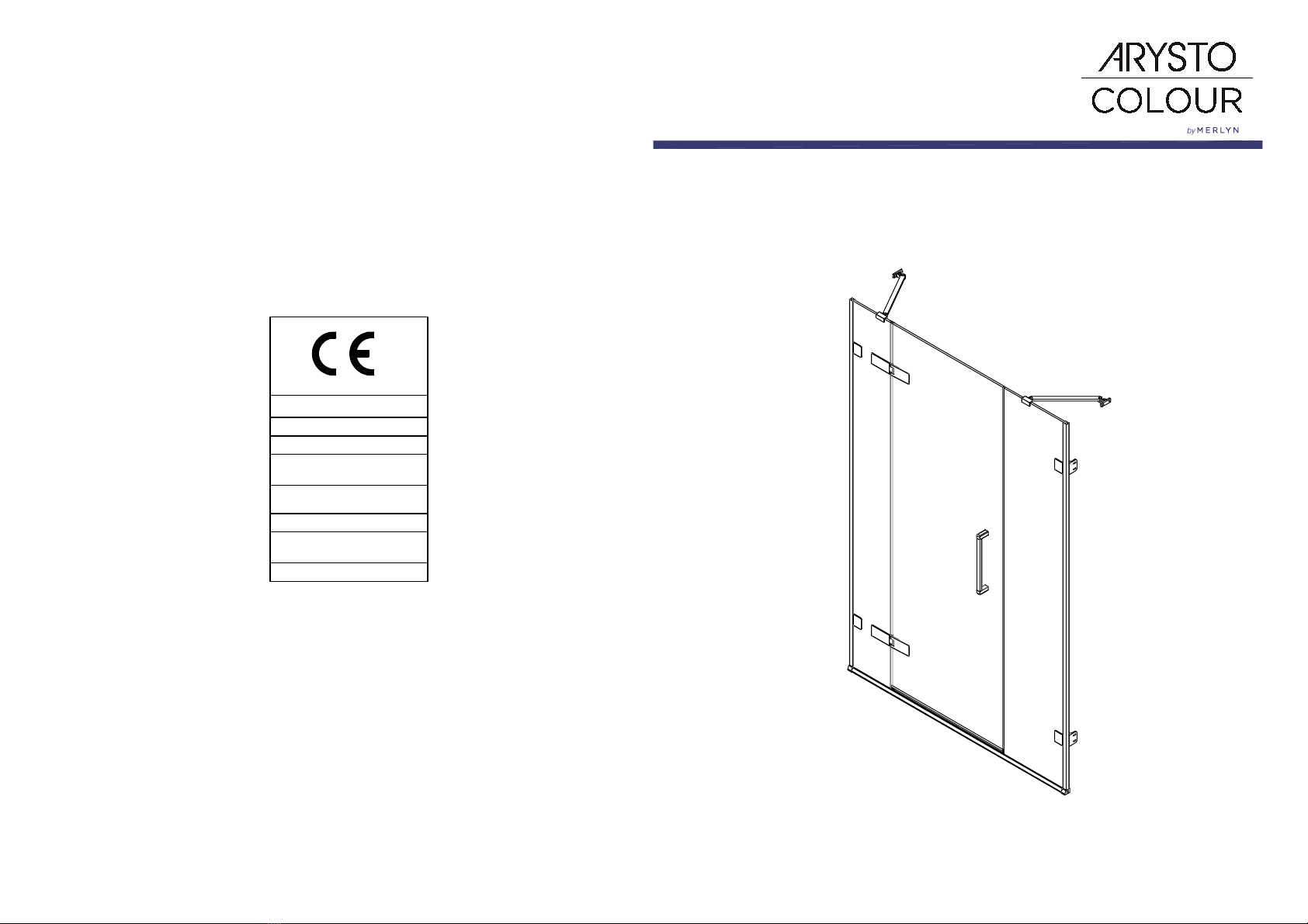
INSTALLATION GUIDE
Hinge Door & 2 Inline
Panels-Recess
www.merlynshowering.com
Merlyn Showering
Unit 8, Purcellsinch Industrial Park,
Dublin Road, Kilkenny, Ireland.
Tel: 00353 56 779 1555
Fax: 00353 56 779 1576
www.merlynshowering.com
To download the Declaration of Performance (DOP) for
this product please use the link below.
https://merlynshowering.com/aftersales-support/dop-certs/
MERLYN
Merlyn Industries Ltd (MER01)
20
EN 14428
Shower enclosures with aluminium
profiles and safety glass
Cleanability
Impact resistance/
shatter properties
: Pass
: Pass
Durability : Pass
Declaration of performance number
CEARH1.2
12
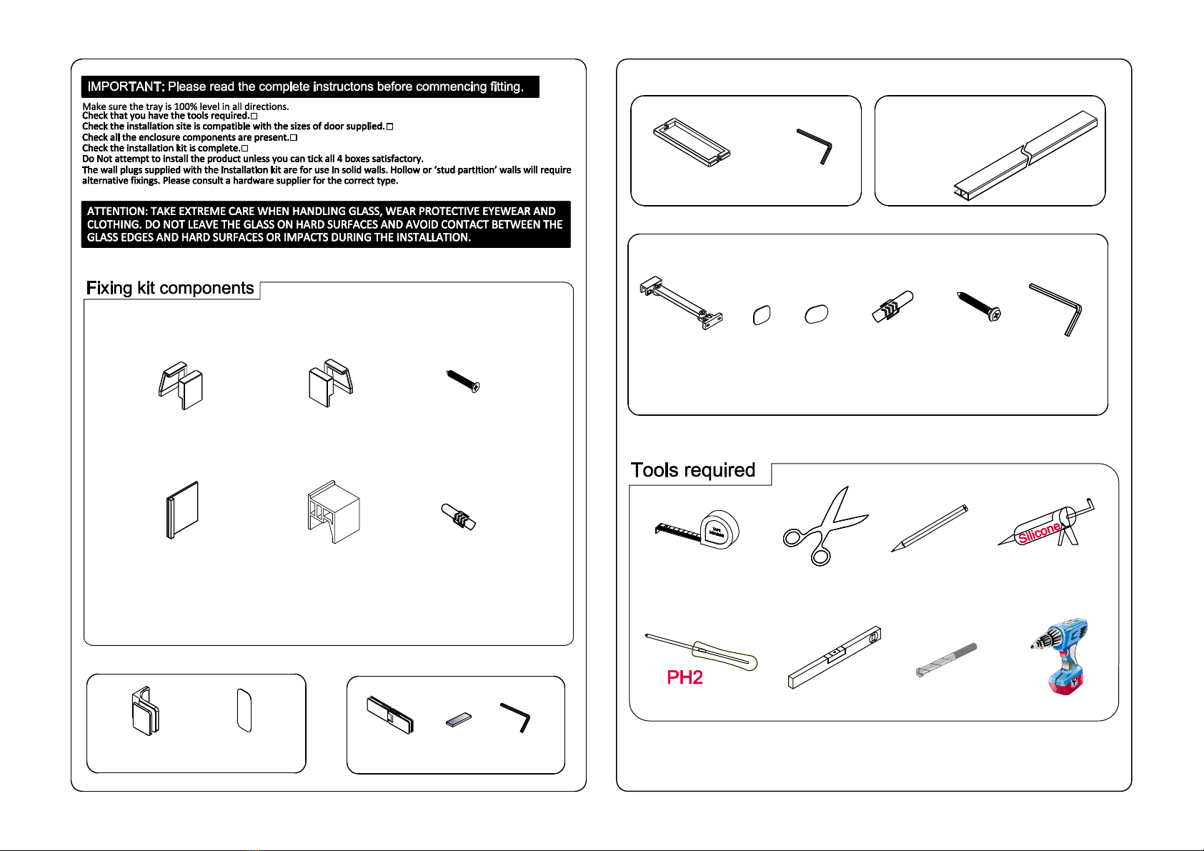
SP010SP281000
1
Door assembly tool
6&8
MGVC45
Installation tool
1
4
MG8x51PLUG
x4
MGST5X65
AC34 AC35
AC25SPACER
11
2
AC13
x4 AC14
x2 A06S0046
2
8S1300511
1
AC07
x1
Bracing bar Wall plug
x4 430 screw
44mm Hex key
22
Clamp
cover cap
x4
Wall bracket
cover cap
x4
AC10
Covercap
x4 Spacer
x 2

34
No. QTY Part No. Part No.
1
2
3
4
5
8
1
2
1
4
No. QTY
7
8
9
2
1
6
Part No.No. QTY
2
1
10
11
12
13
14
15
16
17
1
1
1
2
8
AC13
MG8x51PLUG
MGVC33A1
1
2
3
4
5
6
7
8910
11
12
13
14
15
16
17
GMGHFA
MGVC44LSET/RSET
1
MGVC30A
MGST5X65
1 AC07
GMGCPA
GMGDPA/B/C/D
AC14
AC01
AC34
AC37
AC10
AC35
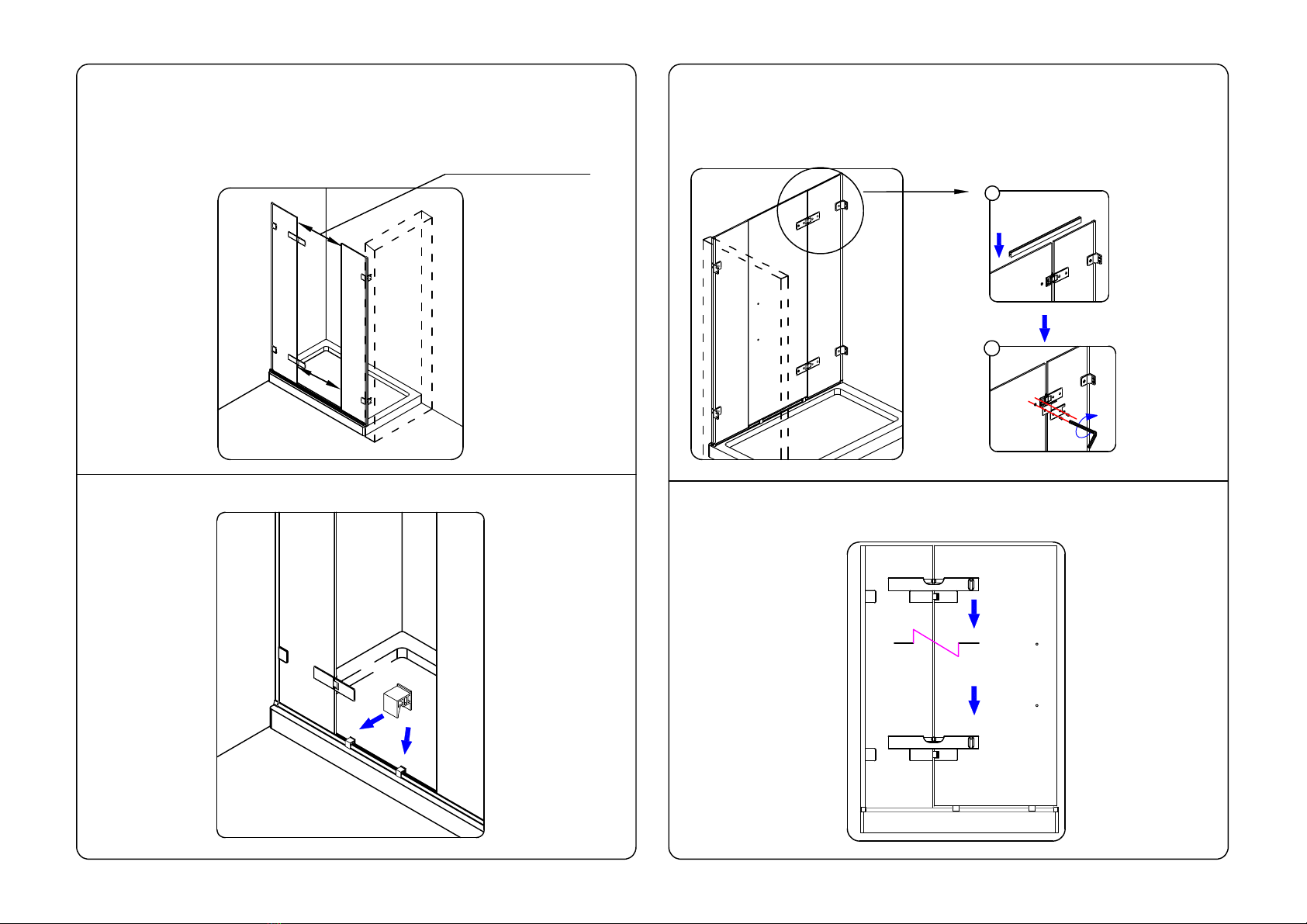
Put bottom track in place on the tray, insert bottom brackets to both ends.
Attention: Keep the sloped side of bottom profile to outside.
Step 2
AC03SL/AC04SL
Step 1 IMPORTANT!
Whether fitting on a tray or on a tiled Wetroom
the tray or floor must be 100% level!
100% level
2A 2B

56
Step 3 Step 4
Before assembling the brackets make sure it is orientated the correct way. Measure
hole centres from top and bottom to determine correct orientation of panel.
Note the differences between the hinged fixed panel (has notch cuts for hinge) and
the closing side fixed panel (no notch cuts).
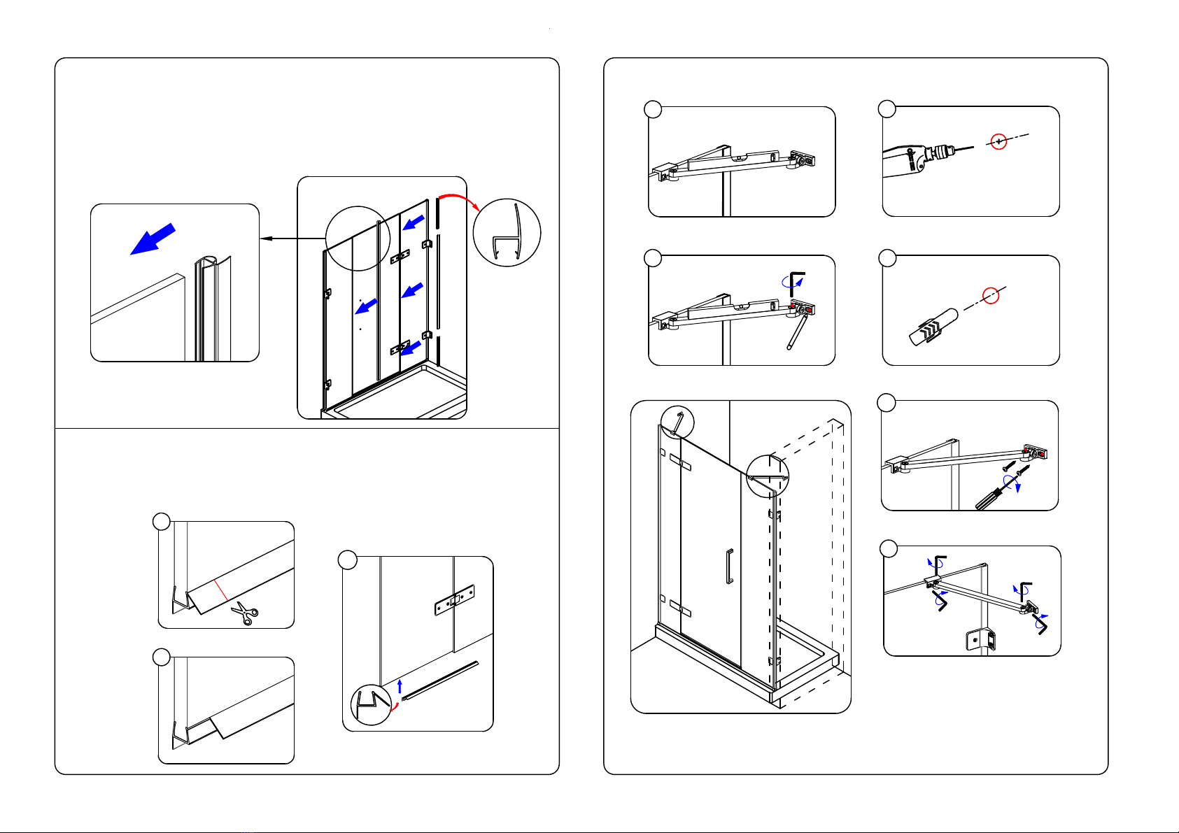
Step 5
Push on wall profile completley ensuring end is flush with the top of the
glass panel.
Top
250mm
Bottom
275mm
THIS WAY UP THIS WAY UP
Hinged fixed panel Closing side
fixed panel Top
250mm
Bottom
275mm
0-15mm Adjustment
0-15mm Adjustment
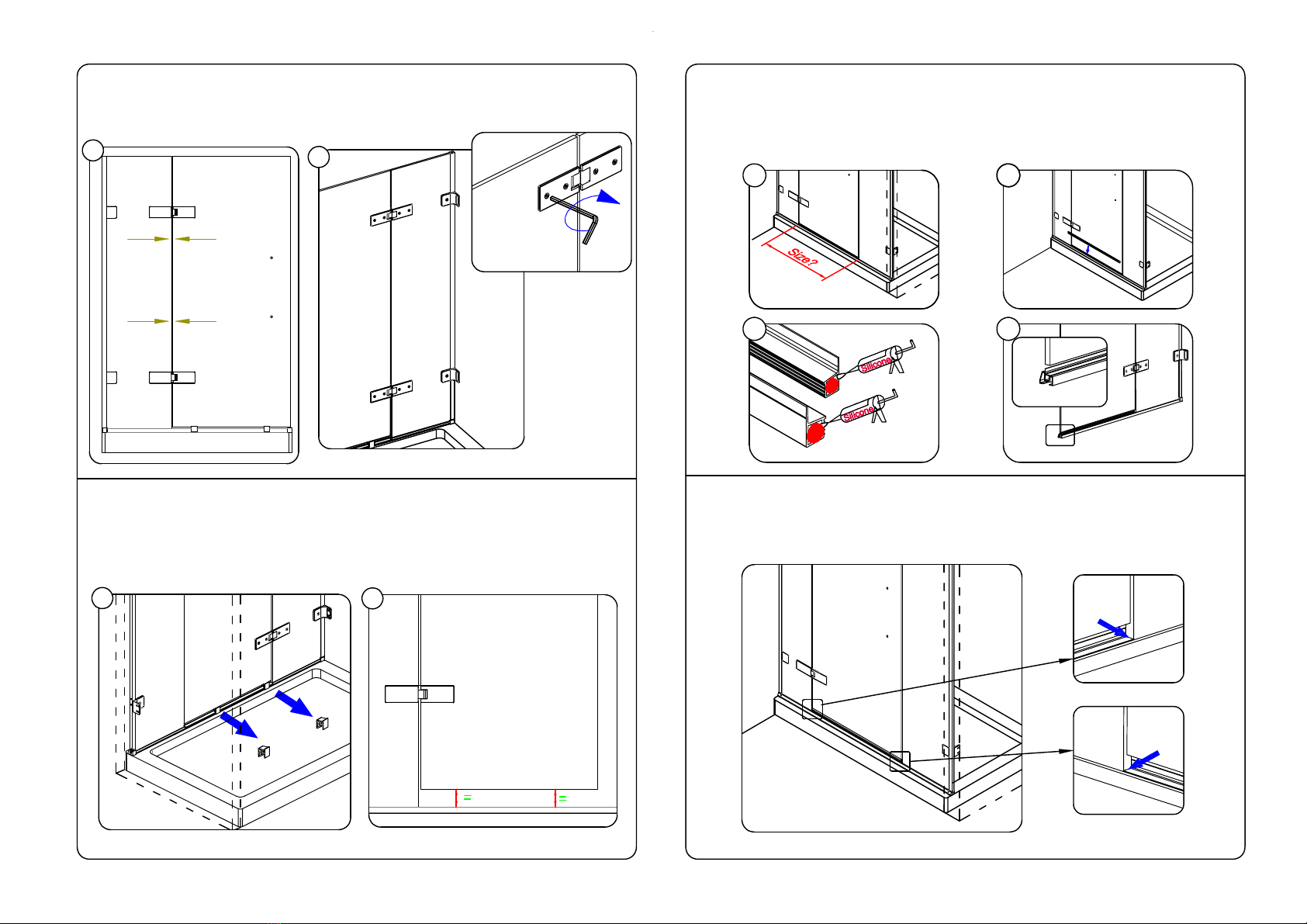
Position the track parallel to the tray edge while ensuring the gap between the ends
of the track and the inside edge of the bracket is within the 0-15mm adjustment.

Step 6
INSIDE
78
INSIDE
Insert wall plugs
Drill holes for hinge
8mm
MG8x51PLUG
Remove both fixed panels and the bottom track, then drill holes with 8mm
diameter masonry bit and insert wall plugs. Ensure the wall plugs are flush with
the tile.
Step 8
INSIDE
Screw 5 65
MGVC45
Step 9
Fix the wall brackets loosely making sure to have the wall bracket in the center
of the hole in the glass.
IMPORTANT ! This is critical as it is where the panel adjusts. If the brackets are
not positioned in the center adjustment will be affected.
Lift the assembled panels into the track. Plumb each panel and mark the centre
of each slot.
A.Place the assembled bottom track back on the
tray and place fixed panel into the track. Fix wall
brackets.
Do not fully tighten, leave enough slack for
adjustment. Secure the top bracket first.
B.Hold glass panel and gently tap profile back
tight against wall using MDF tool provided,
working from bottom to top.
Step 7

Step 10
Check panel for level and fully tighten screws to wall.
9
Step 12
Step 11
10
Do not fully tighten bracket to glass, leave enough slack for adjustment.
Moving
Panel Hinge plate with notch
INSIDE
Fit hinges to inline panel ensuring that the part of the hinge which has a notch
will be on the moving panel side.
Inline Panel
Screw 5 65
Tip: Use MDF tool for
squaring hinges.
Remove back plates from
hinges on moving panel
side and place hinge
plate, washers, bolts and
hex key inside enclosure.
PVC spacer
A
To help align the hinge, place the 2mm clear PVC spacer under the hinge on the
edge of the cutout.
B
Step 13
Check door opening at bottom and make sure that the distance at the top is the
same.
11
Step 15
Gap top and bottom
should be width of
moving panel +12mm
12
Step 16
Loosely fix back plate to hinges ensuring washers are in position and hinges are
level.
INSIDE
15B
Use door assembly tool to hold the door
in place until the hinges are fitted.
locating aids
Step 14 Place locating aids and spacers on threshold, one each side of opening.
Standing inside the enclosure lift the door onto the locating aids. Make sure
you have all the fixings and tools required inside the enclosure.
SP010SP281000
15A
13
Step 18
Step 17
Ensure gap is equal top and bottom, then fully tighten hinge bolts.
gap is equal
gap is equal
INSIDE
4mm ALKEY
17A
INSIDE
INSIDE
14
INSIDE
Step 19
INSIDE
Make sure no gap!
Step 20
Make sure no gap!
INSIDE
Make sure there is no gap at either end.
Door panel
Door panel
Remove top holding strip. To remove door positioning aids open door outwards.
When positioning aids have been removed check gap beneath door is even. If gap is
not equal loosen hinges slightly and adjust.
Measure between edge of fixed panel and the wall and cut infill seal to this
length. Apply a dab of silicone to both ends, insert to bottom profile. Note: The
vertical fin should be positioned to the front of the enclosure.
17B
18A 18B
19A
19B
19C
19D
INSIDE
Step 22
22A
INSIDE
Fit bottom door seal keeping angled fin to inside. Notch fin where it meets the closing
seal to ensure door closes fully.
22C
22B
INSIDE
Step 21
15 16
INSIDE
MGVC33A
Drill with 6mm masonary
drill bit.
MG6x30PLUG
Level the rail.
Mark outline of the
wall bracket.
Step 23 Fix the top rails.
A
B
Left and right hand seal kits (A) are provided, determine handing and use appropriate
seal kit.
Left hand model shown below. Push on longest seal between hinges onto back edge
of moving panel. Take shortest seal and fit to top keeping notch to hinge.
Repeat with longer bottom seal.
Fit closing seal (B) to edge of the inline panel. Make sure to keep fin to the inside.
Fix the wall bracket.
23A
23B
23C
23D
23E
23F

Step 27
INSIDE
Secure caps in place by adding a dab of silicone to the back of each plate.
Step 25 Fit the handle to the door.
INSIDE
17 18
fit wall bracket
caps
AC07
Step 24
INSIDE
24B
Step 26 Adjusting fixed and hinged panels
If after fitting doors and fixed panels and you still need adjustment to align doors
etc, you can achieve this by loosening the screws fixing the plate/hinge to the wall
and the bolts clamping the bracket/hinge to the glass.
Adjust the panels until the desired fit is achieved. Fully tighten all fixings.
Note: If not further adjustment is needed make sure all fixings have been tightened
securely.
24A
INSIDE
INSIDE
INSIDE
Where an angled bracing bar is fitted additional adjustment can be made by:
1) Loosen the 3 screws clamping the glass.
2) Move the glass panel in the direction required(see arrow).
3) Tighten the 3 screws.
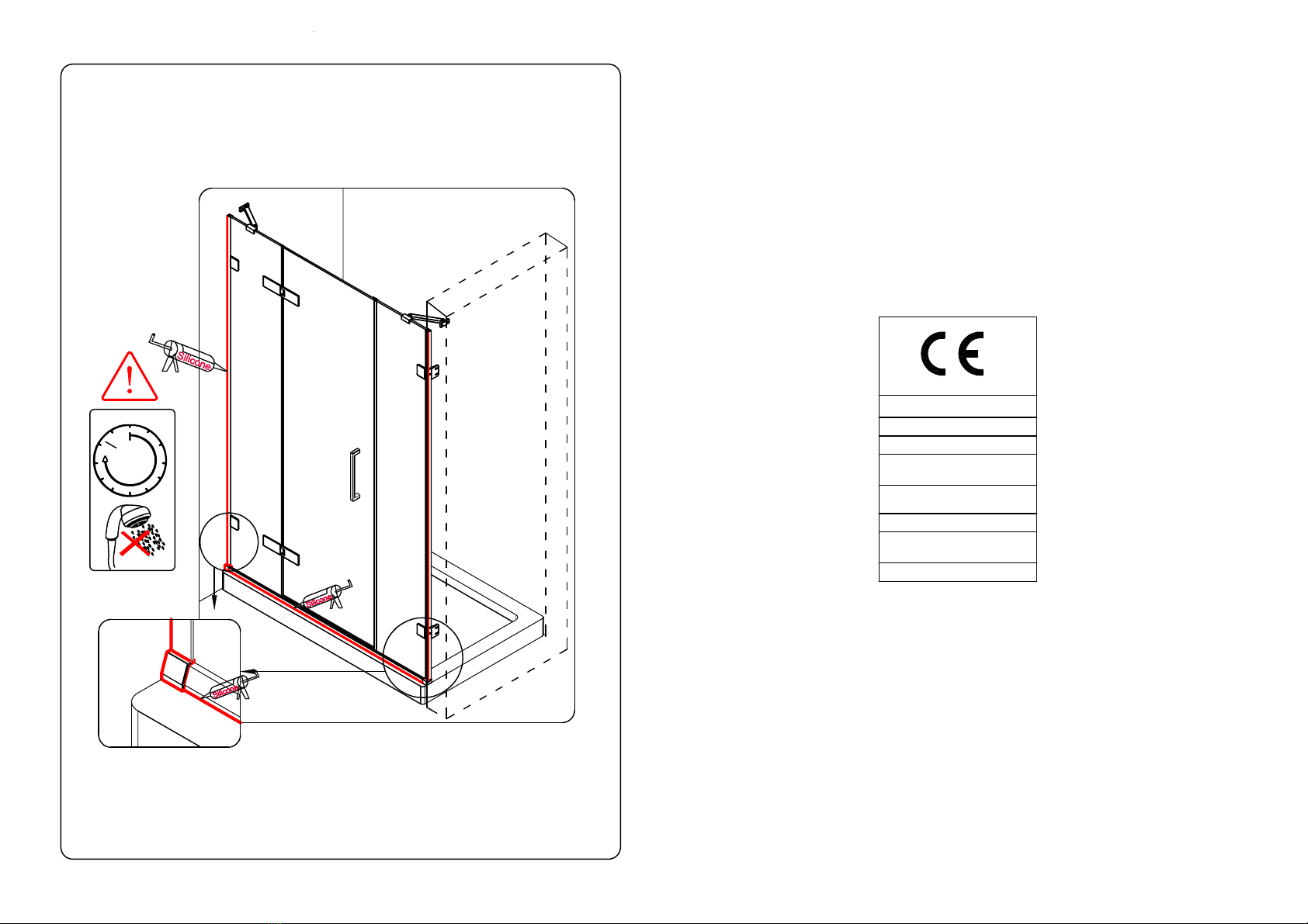
Step 28
Only seal the outside of the enclosure(red line). Do not seal the inside.
Seal vertically along the wall, along the outside edge of the bottom profile and any
joins in the profile, including where the bottom track meets the end brackets.
Sealing your enclosure.
24 h.
19
Make sure all surfaces are thoroughly cleaned and dry before applying sealant.
Merlyn Industries Ltd (MER01)
20
EN 14428
Shower enclosures with aluminium
profiles and safety glass
Cleanability
Impact resistance/
shatter properties
: Pass
: Pass
Durability : Pass
Declaration of performance number
CEARH1.2
Other MERLYN Shower Cabin manuals


Popular Shower Cabin manuals by other brands

Grandform
Grandform ESSENTIAL Assembly instructions

Coram Showers
Coram Showers PREMIER installation instructions

ERLIT
ERLIT ER 10109V Installation and operation instruction

KERRA
KERRA P 135 Assembly and maintenance instructions

Novellini
Novellini NEW HOLIDAY A80 Installation, use and maintenance manual

Kermi
Kermi Raya RA EPR/L TWD installation instructions

Samo
Samo B6811 Assembly instruction

OVE
OVE OWS-607 Installation and user guide

Dreamline
Dreamline MYSTERIE SHDR-61AMZ48 Series installation instructions

Dreamline
Dreamline ENIGMA AIR SHEN-6434480 Series installation instructions

NewLine
NewLine TradePro Curved instruction manual

Dreamline
Dreamline ENIGMA SHDR-6060791272 installation instructions


