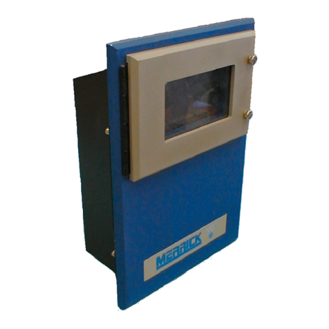
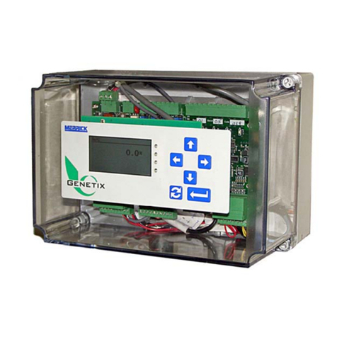
MERRICK MC3 35.00.EX User manual

MC³ 35.00.EX
Weigh Out Batch Controller
Operation and Maintenance Manual
Version C
MERRICK INDUSTRIES, INC.
10 Arthur Drive
Lynn Haven, FL 32444 U.S.A
Tel: +1 850.265.3611
Fax +1 850.265.9768
www.merrick-inc.co
m

Revisions
Beta August 23, 2000 Beta Draft
O February 15, 2001 First Release
C December 9, 2004 Rewritten for Version C
PROPRIETARY NOTE
The information in this manual, including technical data and copies of drawings, embodies
information proprietary to Merrick Industries, Incorporated. This manual is provided to the user of
equipment purchased from Merrick Industries, Inc. for use only in operation or maintenance of
such equipment. Such information in this manual is not to be used, disclosed, copied, or
reproduced in whole or part for any use other than that indicated above, or for any other purpose
detrimental to the interests of Merrick Industries, Inc. Patents owned by Merrick Industries, Inc.
have been issued or are pending on at least some of the information in this manual, and
unauthorized use of this subject matter of such patents is a violation of such patents and is
prohibited

CONTENTS
Introduction ........................................................2 Bach Parameters ....................................24
Safety.............................................................2 Fast Feed Spd ....................................24
In General..................................................2 Fine Feed Spd ....................................24
Electrical Precautions................................2 Fine Feed Wt ......................................24
Related Publications......................................2 Fine Feed Tm .....................................24
Manual Conventions......................................2 Fine Feed Adj .....................................24
Screens .....................................................3 Curr Preact .........................................24
Solving Problems...........................................3 Preact Limit.........................................25
Technical Support......................................3 Pre Max Chang...................................25
System Overview...............................................4 Preact Apply........................................25
Batching Control............................................4 Max Batch Tm.....................................25
Key parameters.........................................4 Batch Dev Hi, Lo.................................25
Load Cell Signal Conditioning...............4 Auto Batch Tm....................................25
Rate Calculation....................................5 B Settle Time ......................................25
Setpoint Signal Conditioning.................5 Hopper Parameters.................................26
Setpoint filter.........................................5 Fill Weight...........................................26
Stability Calculation...............................5 Heel Weight ........................................26
Hopper Parameters...............................5 Empty Weight......................................26
Batch Parameters .................................6 Fill Time ..............................................27
State Logic.....................................................6 Clean Time..........................................27
Feeder States............................................6 Empty Time.........................................27
Feeder State Transitions...........................8 Fill Gt Time..........................................27
Block Conditions ...................................9 Vibrator Time ......................................27
Issuing commands................................9 Stability Settings......................................27
Hardware..........................................................10 Stable Time.........................................27
Getting Started.................................................11 Stable Span ........................................28
Installation....................................................11 Stable Samples...................................28
Starting the controller ..................................11 Calibrate Settings....................................28
Quick Setup.............................................11 Cal Weight ..........................................28
Main Screens...............................................12 E-Cal Liveload ....................................28
Main Screen ............................................12 Zero Weight ........................................28
Batch Statistics Screen ...........................13 Scale Factor........................................28
Warnings .................................................14 Quick Setup.............................................28
Faults.......................................................15 Sample Rate............................................29
Setting the Setpoint .....................................15 Display Parameters.................................29
Manual Setpoint Method.....................17 Backlite Off..........................................30
Action Menu.................................................17 Displayed FR ......................................30
Batch Control Buttons..............................17 Loss Slots ...........................................30
State indication text.................................18 Setpoint Slots......................................30
Setpoint Method Text ..............................18 Date/Time Settings..................................30
Batch Statistics........................................18 Inputs and Outputs Menu............................30
Reset S-Total...........................................18 Analog Inputs Setup................................30
Reset G-Total..........................................18 Analog Setpoint Setup........................31
Diag Menu...............................................18 Panel Meter Setup..............................31
Home Screen...........................................18 Analog Input Numeric Parameters .....31
Calibrate Menu........................................18 Analog Input defaults and limits..........32
Printer Menu............................................18 Analog Outputs Setup.............................32
PF buttons...........................................20 Analog Outputs Numeric Parameters.33
Settings Menu..........................................21 Digital I/O Mapping..................................34
Setting Up Your Controller...............................22 Digital Inputs Setup.............................35
Settings Menu Items....................................23 Logical Inputs......................................35
Select Units .............................................23 Physical Inputs....................................38
Set Dec Pts..............................................23 Digital Outputs Setup..........................38
Design Capacities....................................23 Logical Outputs...................................39
30.10.EX O&M Manual i

List of Physical Outputs ......................42
EMT Settings...........................................43
Divisor .................................................43
Pulse Width.........................................43
Comm Settings........................................43
Comm 1 Numeric................................44
Comm 2 Numeric................................44
Limit Switches..........................................45
Weight Limits.......................................45
Panel Meter Limits ..............................45
Calibrating Your Controller...............................46
Calibration Menu..........................................46
Zeroing Procedure...................................47
Material Calibration..................................48
Weight Procedure....................................49
Electronic Calibration ..............................50
E-Cal Factor Procedure...........................52
Analog Input Procedure...........................52
Diagnosing Problems.......................................54
The Crash Screen .......................................54
Start-Up Crash.........................................54
Parameter Corruption .........................54
Controller Firmware Upgrade..............54
Fatal Error Crash.....................................55
Forcing a Parameter Reset ................56
Diagnostic Menus........................................56
HPAD Diagnostics...................................56
Communication Diagnostic .....................57
Clean Off Screen.....................................59
Calibrate Diag .........................................59
Analog Diagnostics .................................59
Digital Diagnostics...................................60
Mapping view......................................60
List View..............................................61
Faults and Warnings Diagnostics ...........61
DF1 Diagnostics......................................61
Register Monitor......................................61
Misc Data Diagnostics.............................62
Modbus Diagnostics ...........................63
Diagnostic Settings......................................63
HPAD Settings ........................................63
CAL.....................................................63
ZERO..................................................63
GAIN...................................................64
Set Status ...........................................64
# of HPAD’s ........................................64
Password Settings ..................................64
Register Editor ........................................64
30.10.EX O&M Manual ii


INTRODUCTION
SAFETY
The Merrick MC³ Controller is used for the control of process weighing equipment. To
insure personnel safety please read the following instructions and precautions carefully.
In General
1. Observe all standard precautions that pertain to moving machinery.
2. Observe all standard precautions that pertain to electrical drives and electrical
controls.
3. Pay particular attentions to special notes and precautions that appear throughout
this manual.
4. Please read and familiarize yourself with this entire manual before attempting
service or repair of the Merrick MC³ Controller. If you have any questions or
problems please call the Merrick Service Department for assistance.
Electrical Precautions
1. Before undertaking work on the electrical system, the drives, or the Controller,
open the main-disconnect switches and lock boxes. Work should never be
performed on the Controller with power on the unit. It is recommended to
disconnect the power from the controller before attempting any service
procedure.
2. Verify that all grounds that are called for on the wiring diagrams are in place and
are securely connected. Proper grounding not only helps insure your personal
safety, but also is necessary for the proper operation of the controller.
3. If it is necessary that you must work in or near areas of live high voltage, always
keep one hand clear of the machine, the cabinet, or any other conductors to
avoid the possibility of electrical shock traveling across your chest.
4. NEVER impair or disable the function of a fuse or a circuit breaker.
IF YOU ARE IN DOUBT ABOUT ANY PROCEDURE, CONTACT THE MERRICK
SERVICE DEPARTMENT.
RELATED PUBLICATIONS
You will find related publications regarding MC³ controller hardware, internal register
database information and industrial networking capabilities at the support web site at
http://www.merrick-inc.com/mct. In the rest of the manual, this is referred to as [MCT].
MANUAL CONVENTIONS
NOTE: Any additional information that may be useful follows the note marker.
CAUTION: Be careful, certain settings may cause problems.
WARNING: Follow the directions prescribed in the warning. Serious problems can occur if the
recommendations are not followed.
R[254] This is a register reference to a parameter, in this case register number 254.
Some parameters are rarely used or considered to be experimental. They can be
inspected or changed, using the Register Editor. See page 64.
35.00.EX O&M Manual 2

Screens
A graphic of this size and type will show the functions available and/or information
available in diagnostic screens and special display screens.
SOLVING PROBLEMS
Several methods are available for use to assist in solving problems. The application
contains help buttons for giving text explanations of the current selected function or
parameter. Also included in this manual is a troubleshooting section to assist in solving
technical problems (Diagnosing Problems, page 54).
Technical Support
Merrick provides customer technical and spare part support 24 hours a day, seven days
a week. Assistance is available by calling +1.850.271.7878. After normal business hours,
you will receive instructions on how to reach the support technician on call. You can also
When you call or email Merrick for Technical Support, please have your machine serial
number or a controller serial number. This information will better help us to serve you.
35.00.EX O&M Manual 3

SYSTEM OVERVIEW
A Weigh-Out batching system is designed to produce batches of material with a pre-
determined weight. A weigh hopper is placed on load cells, producing a signal
proportional to the weight of the hopper and its content. At the bottom, there is a variable
speed feeding device, such as a material screw or a vibrating pan. The MC³ controller
will run the feeding device in such a way that the weight reduction in the hopper
corresponds to the desired value (the setpoint). Typically the feeding device first runs fast
(Fast Feed) and then switches to a slower speed (Fine Feed), as the weight loss
approaches the setpoint.
When the weight of the hopper content reaches a pre-set low weight, called the Heel
Weight, the MC³ controller will call for the hopper to be filled, up to another pre-set
weight, called the Fill Weight. During the filling, no batching can take place, and the
feeding device is stopped. Typically, an automatic valve or feeding device is used to re-fill
the weigh hopper, under control of the MC³.
BATCHING CONTROL
Setpoint Signal Load Cell Signal
Setpoint Signal
Conditioning Load Cell Signal
Conditioning
Setpoint Filter Rate
Calculation
State Logic
Hopper
Parameters
Batch
Parameters
Feeder Speed
Demand Signal
Stability
Calculation
The MC³ 35.00.EX controller uses a self
correcting algorithm to optimize batch
accuracy and batch performance. There is
always a trade-off between the two, meaning
that that faster batching reduces batch
accuracy and vice versa.
Key parameters
Each of the function blocks above has one or more parameters associated with it. They
all have to be set properly for good batching control. Most of them can be set
automatically, by running Quick Setup (see page 28). Some of them can be continuously
updated by the controller itself, as a part of a self-adjusting scheme.
Load Cell Signal Conditioning
The weight signal conditioning block takes the Load Cell Signal as an input, passes it
through an A/D converter, called the HPAD, and produces a weight value as an output.
Parameters are:
Zero Weight The weight of the hopper, feeding device etc when the hopper is
empty. Set by running a Zeroing Procedure (page 47). You can also
set it manually. See Zero Weight on page 28.
Scale Factor A divisor to translate the load cell signal counts from the load cell A/D
converter, the HPAD, to usable engineering units, such as lb or kg.
Set by running a Material Calibration (page 48) Weight Procedure
35.00.EX O&M Manual 4

(page 49) or Electronic Calibration (page 50). You can also set it
manually. See Scale Factor on page 28.
Sample Time How often the controller re-calculates all internal variables. See
Sample Rate on page 29. Normally, two different sample times are
used, one while feeding or filling, and a longer time while idling.
Rate Calculation
This is where the feedrate through the feeding device, R[251], is calculated, by taking the
difference between two samples of the Weight.
Loss Slots How many samples the two weight values are separated to calculate
the Rate. Set to 10 by default. See Loss Slots on page 30.
Setpoint Signal Conditioning
The Batch Setpoint is taken from the Network, an Analog Input or locally on the controller
screen. If an analog input is used, the Setpoint has to be calculated in a similar way as
the Weight. The analog Setpoint signal taken as input passes through an A/D converter
and produces a Batch Setpoint as an output. All parameters can be set in the Analog
Setpoint menu. See page 31. There is also an automatic calibration procedure for setting
the counts, Analog Input Procedure (page 52). Parameters are:
SP Lo Cnts A value in counts from the A/D converter representing a Minimum
setpoint.
SP Hi Cnts A value in counts from the A/D converter representing a Maximum
setpoint.
SP Min Value This is the minimum setpoint value, normally zero.
SP Max Value This is the maximum setpoint value, normally the same as the Max
Batch Weight for the feeder.
Setpoint filter
A fluctuating setpoint is undesirable. To avoid fluctuations due to noise on analog signals
or in networked follower implementations, this averaging filter can be used to produce a
smoother value. It takes the Batch Setpoint as input and produces the Average Setpoint,
R[245], as output, by calculating the arithmetic average of a settable number of samples.
There is only one parameter:
Setpoint Slots How many setpoint samples used to form the Average Setpoint. Set
in Setpoint Slots, page 30.
Stability Calculation
The controller uses two live weight values, one immediate, R[193], characterized by fast
update, and one high quality, R[184], updated only when the weight value in the hopper
is stable. When precision batching, the stable weight is acquired before and after the fast
and fine feed. The immediate weight is used during feeding and re-fill. Parameters are
set in the Stability Settings menu. See page 27.
Stable Time How log the controller will wait for stability.
Stable Span Max allowed weight difference between the Stable Samples.
Stable Samples The immediate weight has to stay within Stable Span for this number
of samples.
Hopper Parameters
The Hopper Parameters deal with the material in the hopper, filling, emptying etc. They
are all set in the Hopper Parameters menu. See page 26.
Fill Weight The hopper weight at which the fill gate closes when the weigh
hopper is re-filling.
35.00.EX O&M Manual 5

35.00.EX O&M Manual 6
Heel Weight The hopper weight at which a re-fill normally takes place. There are
several exceptions to this rule, for example, no re-fill takes place
during Fine Feed. The Heel Weight may have to be set surprisingly
high, especially if the material is floodable.
Fill Time Max time allowed for a re-fill.
Batch Parameters
The Batch Parameters deal with the batching of the material in the hopper They are all
set in the Bach Parameters menu. See page 24.
Fast Feed Spd The speed, in %, of the feeding device during Fast Feed.
Fine Feed Spd The speed, in %, of the feeding device during Fine Feed.
Fine Feed Wt As the Batch Total approaches the Setpoint, the controller switches
from Fast Feed to Fine Feed. The switch point is when the batch total
equals the setpoint minus the Fine Feed Wt. A value of Zero will
eliminate the fine feeding.
Fine Feed Tm The Fine Feed Wt will be adjusted, after every batch, so that the fine
feed time equals this parameter. A value of Zero will leave the Fine
Feed Wt unchanged.
Fine Feed Adj Determines aggressiveness of the Fine Feed adjustment, when timed
Fine Feed is used.
Curr Preact As the Batch Total approaches the Setpoint, the controller will turn off
the feeder before the batch total is reached. The switch point is when
the batch total equals the setpoint plus the Preact. Hence the Preact
is typically a negative value. The parameter is normally adjusted by
the controller after every batch.
Preact Limit Absolute limit of the Preact, positive or negative.
Pre Max Chang How much the Preact is allowed to change from batch to batch. A
value of Zero will disable the automatic updating of the Preact.
Preact Apply The fraction, in %, of the last batch error (Setpoint minus Batch Total)
that is used to adjust the Preact.
STATE LOGIC
Batching is a cyclic operation. The hopper must also be filled periodically. The typical
operation will follow a sequence like Fill, Batch, Batch, …, Fill, …, Batch, …, Cleanout.
The sequences are affected by external commands, the weight in the hopper and Faults.
Feeder States
The controller uses states for digital control. Internally, the State is a numerical value in
R[261]. In networked applications, it is a good idea to monitor the State value, and use it
for HMI indication purposes.
On the next page, all visible states are listed. In the Main and Batch Statistics screen,
you can see Text 1 and Text 2. In the Action Screen, you can see the Action Screen
Text.

Text 1 Text 2 R[261] Action Screen Text Comment
Paused 1 Paused. Clear or Start The (ongoing) batch was paused by a Pause Batch command
Paused BLOCKED! 1 Paused. Clear or Start A Fault occurred during batching. After the Fault has been acknowledged,
the ongoing batch has to be either cleared or resumed.
Idle 2 Idle - Ready For Start The system is ready for a Start Batch command
Idle Cleanout 26 Cleanout by weight The hopper is cleaning out, and the weight has not yet reached the Empty
Weight.
Idle Cleanout 27 Cleanout by time The hopper is cleaning out, the weight is below the Empty Weight.
Idle Empty 28 Cleanout Completed The hopper is cleaned out, and there is still a cleanout command.
Idle BLOCKED! 2 Idle – Blocked or Manual Setpoint Method is Manual, there is a Fault, or the Feeder Block logical input
is On.
Stable Chk 5, 6 Stable Weight before
feeding The stable weight before start of feeding is being acquired
Fast Feed 9 Fast Feeding
Fine Feed 12 Fine Feeding
Stable Chk 14, 15 Stable weight after
feeding The stable weight after end of feeding is being acquired
Paused or Idle Re-Fill 23 Filling up The weigh hopper is being re-filled
Close Gate Re-Fill 24 Closing Fill Gate Settling after re-fill
35.00.EX O&M Manual 7

35.00.EX O&M Manual 8
Feeder State Transitions
During operation, the controller state will follow a sequence. This table lists all possible transitions between states. During normal batching, Next
State follows the Current State. All other columns indicate to what state the MC³ will go on an external command. To find out what the controller
will do if you issue a command, start on the row for the current state, and go the column of the command.
Current State Next State Start Batch Stop Batch Start Fill Stop Fill Start Cleanout Stop
Cleanou
t
Clear Batch
Paused Note 1 Stable Chk
Before Re-fill Cleanout weight Idle. Note 2
Idle Note 1 Stable Chk
Before Re-fill Cleanout weight Idle. Note 2
Stable Chk
Before Fast Feed Idle. Note 2
Fast Feed Note
3 Fine Feed or
Re-fill. Note 3 Stable Chk
After, Paused
Stable Chk
After, Re-fill Stable Chk,
Cleanout Idle. Note 2
Fine Feed Note
4 Stable Chk
After Stable Chk
After, Paused
Stable Chk
After, Re-fill Stable Chk,
Cleanout Idle. Note 2
Stable Chk After Idle Cleanout weight Idle. Note 2
Re-fill Close Gate Paused Stable Chk
Before or Idle
Cleanout weight Idle. Note 2
Close Gate Fast Feed or
Idle Idle. Note 2
Cleanout weight Cleanout time Idle Idle. Note 2
Cleanout time Cleanout
Done Idle Idle. Note 2
Cleanout Done Idle Re-fill Idle. Note 2

Note 1 There is no continuing state. A command has to be issued.
Note 2 A Clear Batch command will end batching, filling or cleanout. Batch statistics are
not updated. State will change to Idle.
Note 3 If the Heel Weight is reached during Fast Feed, state changes to Stable Check
After, then to Re-fill. If the Batch Total is at or above the Batch Setpoint, no Fine
Feed takes place. State changes to Stable Check After, then Idle. This behavior
can be altered. See Heel Weight on page 26.
Block Conditions
A Block Condition is either an unacknowledged fault or the logical input Feeder Block is
On. The State will go to Paused, unless it was Idle when the block condition occured.
Issuing commands
There are three sources for commands:
1. Local from the MC³ screen.
2. Remote by means of Logical Inputs mapped to Physical Inputs. The logical inputs
are named “Rem Start Batch”, “Rem Stop Batch” etc.
3. Network by means of Logical Inputs mapped to External Inputs. The logical inputs
are named “Net Start Batch”, “Net Stop Batch” etc.
By default, Local, Remote and Network inputs work in parallel. Pushing the Start Batch
button, setting the Rem Start Batch or Net Start Batch input has the same effect. By
setting R[078] to 1, a more stringent scheme is used for the commands, so that
commands can only be issued from the Setpoint Method source. See Setting the
Setpoint on page 15. As an effect, no command buttons will be visible in the Action
Screen unless the Setpoint Method is Local.
35.00.EX O&M Manual 9

HARDWARE
The MC³ Controller has been designed to control many different types of feeding,
weighing and metering equipment. This allows for easier maintenance and simplified
training.
The Standard Merrick MC³ 35.00.EX Controller consists of an Enclosure, an LCD
Display, Card Stack and a Power Supply. Refer to MC³ Hardware manual for details. It is
available for download from [MCT].
The hardware manual describes the different enclosures, installation, wiring and
hardware related configuration and troubleshooting.
35.00.EX O&M Manual 10

GETTING STARTED
INSTALLATION
1. Carefully unpack the controller and inspect it for obvious damage because of
shipping or handling. If the unit appears to be damaged in any way, contact the
Merrick Service Department for assistance.
2. Mount the controller in your panel, following the instructions on the drawings in
the MC³ Hardware Manual. Make sure there is adequate clearance around the
unit for maintenance and ventilation.
3. Insure that the Power is disconnected from the Power supply. Make the wiring
connections to the controller, following the instructions on your electrical
connection diagram.
4. Verify all wiring connections before re-applying power to the unit.
STARTING THE CONTROLLER
Before initially using the controller, you should go through the following steps.
1. Check all wiring. Normally, a connection drawing is supplied. At a minimum, the
load cells and Power must be connected for the controller to operate. Read more
about inputs and outputs in the MC³ Hardware Manual.
2. Apply power to the controller. During power up several operations are being
performed. This sequence takes twenty seconds. The start up screen counts
down the time remaining during the start up sequence. Check for any error
messages during the power-up sequence.
Start-up Screen
3. The controller is normally pre-programmed from the Merrick Factory for your
specific application. A document called the Programming Specification Sheet
(Spec Sheet) is inserted in the last section of the Operator’s manual. The Spec
Sheet contains a record of all parameters.
4. If the controller has not been programmed, or requires programming changes,
see the Quick Setup (page 11) procedure. Remember to record all changes to
the parameters on the Spec Sheet. Merrick keeps a record of all Spec Sheets in
a database. If you forward the updated Spec Sheet to the Merrick Customer
Support Department, they will update the database.
5. Choose Set Point method to be used by your application. See Setting the
Setpoint on page15.
6. Change the Calibration, Diagnostic and Setup passwords to protect your
settings.
Quick Setup
This is a start up procedure to follow when you have to set up a controller that has never
been used before. Following this procedure will overwrite all parameters in the controller.
35.00.EX O&M Manual 11

1. Enter the following parameters:
a. Units
b. Design Weight
c. Design Feedrate (Set the Design feedrate to a value higher then the
system should be able to obtain.)
d. Calibration Weight
e. Configure Analog I/O
f. Map Digital I/O
2 Perform the following steps to calibrate the scale:
a Run a Zero procedure. See Zeroing Procedure on page 47.
b Run Weight or Electrical Calibration procedure. See Weight Procedure
(page 49), or Electronic Calibration (page 50) for the method for
performing the calibration procedures.
c. Repeat the Zero Procedure
3. Run the feeder, using Manual Speed Setpoint Method at 100 % output with
material. Observe the feedrate in the Batch Statistics screen. When the feedrate
is stable, record the value. Enter this value into the design feedrate parameter.
You may round this value down appropriately. This value should be close to what
the system can obtain at 100% output.
4. Perform the Quick Setup (page 28) function. This will set reasonable values for
parameters in the controller.
5. Verify all parameters for correct values.
6. Run test batches and adjust the stability parameters so that the weight is stable
when idling and not stable while fast feeding.
MAIN SCREENS
There are two main screens:
Main Screen Default view of all essential operational parameters.
Batch Statistics Batch specific live values and statistical data.
Main Screen
The first you will see after start-up countdown is the Main Screen. It is designed to
provide all essential information at a glance. It also allows you to enter the sub menus for
setting the controller parameters, calibration and other functions.
Feeder Screen
This is what you see in the Main Screen:
Item Description
Abracadabra
Powder Editable text string, normally used to identify the material in the
hopper. See Printer Menu, on page 18. The default text is “MERRICK
INDUSTRIES, INC.”
35.00.EX O&M Manual 12

Item Description
37.50 lb Net (material) weight in the hopper. Also called Immediate Weight.
_F Graphical representation of the Fill Weight. See Fill Weight, page 26.
_H Graphical representation of the Heel Weight. See Heel Weight, page
26.
0.0% Speed Demand Signal for the feeding device.
GT: Grand Total. See Page 18.
Action Menu Button to reach the Action Menu. See Action Menu, page 17.
ST: Sub Total. See Page 18
Local Setpoint Button to reach the Setpoint Menu. See Setting the Setpoint,
page15.
BT: Actual Batch Total.
SP: Actual Batch Setpoint.
“Idle” Variable text for Batch State. See Feeder States on page 6.
“ “ (Empty) Help text for Batch State. See Feeder States on page 6.
“Stable” Stable weight indicator. Blank when the hopper weight is unstable.
11/22/04 Date. Format: Month/Day/Year.
01:45 PM Time. Format: Hour (0-12):Minute AM/PM.
Batch Statistics Button to reach the Batch Statistics screen.
Batch Statistics Screen
A statistics screen is available to monitor immediate data about the current batch, as well
as some statistics.
Batch Statistics Screen
Item Description
Fast Feed Variable text for Batch State. See Feeder States on page 6.
SetP Current Batch Setpoint.
Curr: Actual (live) Batch total.
Prev: Batch Total for previous batch.
Accu: 100
TotalBatch
intSetpo •
∑
∑(Averaged batch accuracy).
Wt: Weight of material in hopper.
Rate: Actual (live) feedrate.
Cntr: Batch counter. Increments for every completed batch.
High: Highest Batch Total since statistics were cleared.
Low: Lowest Batch Total since statistics were cleared.
Ave: Average Batch Total since statistics were cleared.
35.00.EX O&M Manual 13

Item Description
B tm: Total batch time for last completed batch.
F tm Fine Feed time for last completed batch.
Prea: Preact used in this batch.
Prev: Preact used previous batch.
Home Screen Button to reach the Main Screen.
Action Menu Button to reach the Action Menu. See Action Menu, page 17.
Local Setpoint Button to reach the Setpoint Menu. See Setting the Setpoint,
page15.
Clear Statistics Button to clear all statistic related values.
There is an alternative batch statistics screen, more suitable when the batch setpoint
changes often. By setting R[623] to 1, Accu: is replaced with SDev:, Standard deviation.
Ave: is replaced by Merr:, mean error. Both are expressed in percent of the Batch
Setpoint, using recursive formulas. For every batch, the Batch Error, in %, is calculated:
100
SST
En
nn
n•
−
=
Where E is the error, T is the Batch Total and S is the Batch Setpoint. The Mean Error, X,
(Merr:) is recursively updated:
1n EXn
Xnn
1n
+
+•
=
+
Merr: should converge to Zero if the Batch Parameters are set correctly.
Finally, the Standard Deviation, D, (SDev:) is recursively updated:
()
2
n1n
2
n1n XE
1n1
n1n
DD +•
+
+
⎟
⎠
⎞
⎜
⎝
⎛−
=++
Warnings
A Warning indicates a potential problem and calls for your attention. Any logical input or
output can be configured to qualify a warning. See Digital I/O Mapping on page 34. The
Warnings button is visible in the main screen if there is an active warning condition or
there has been a warning condition that has not yet been acknowledged.
Main Screen with Warning Indicator
Pushing the Warnings button takes you to the Warnings screen. The following screen
shot shows the default warnings. Your I/O configuration may be different, producing a
different Warnings screen.
35.00.EX O&M Manual 14

Warnings screen
There is an active indicator to the left of the text ( = On = Off). There is also a “did
occur” indicator to the left of the active indicator. You can acknowledge one warning at
a time. Use the up and down arrow buttons to move the selection box to the Warning you
want to acknowledge, and push Acknowldg. If you want to acknowledge all warnings,
push the Acknowldg All button. You can’t acknowledge an active Warning, that is, if the
active indicator is on ( ).
Faults
A Fault indicates a malfunction that prevents the feeder from running. Any logical input or
output can be configured to qualify a fault. See Digital I/O Mapping on page 34. The Fault
button is visible in the main screen if there is an active fault condition or there has been a
fault condition that has not yet been acknowledged.
Main Screen with Faults Indicator
Pushing the Fault button takes you to the Fault screen. The following screen shot shows
the default faults. Your I/O configuration may be different, producing a different Faults
screen.
Faults screen
The Faults Screen works just like the Warnings Screen. You can’t start the feeder if the
there is an unacknowledged Fault.
SETTING THE SETPOINT
You reach the Setpoint Screen by pushing the Setpoint button in the Main or Statistics
Screen. The button may be password protected. When a password is setup, you will
have to enter a password.
35.00.EX O&M Manual 15

Unchanged Local Setpoint
The “Local On Screen” text indicates the current setpoint method. Possible methods that
can be displayed are:
•Local On Screen. The setpoint is entered here, in the Setpoint Screen, by using the
Numeric button.
•Remote discrete inputs. A signal to a configured analog input is used for the batch
setpoint.
•Network inputs. The setpoint is written to the controller using one of the available
communication protocols. See Comm Settings on page 43.
•Network (Fallback to Local). Network inputs are used as long as there is no
communication timeout. If a timeout occurs, the Local setpoint is used.
•Local (Fallback fr Network). Local inputs are used because there is a
communication timeout. Before the timeout occurred, the Network (Fallback to
Local) setpoint was used.
•Network (Fallback to Remote). Network inputs are used as long as there is no
communication timeout. If a timeout occurs, the Remote setpoint is used.
•Remote (Fallback fr Network). Remote inputs are used because there is a
communication timeout. Before the timeout occurred, the Network (Fallback to
Remote) setpoint was used.
The fallback scheme is engaged by turning on the Force Comm SP logical input. See
Logical Inputs, on page 35.
The “Curr: 10.00 lb” text indicates your current batch setpoint value.
You change the setpoint method with the Local button. The text on the button will cycle
through Local, Remote, Network and Manual.
NOTE! The Manual alternative is only available in the Idle state. The Numeric button is only
available in Local or Manual setpoint method.
As soon as you push the setpoint method button, a new button, Accept, occurs:
Changing the Setpoint Method
The number between the Remote and Accept button indicates what the new setpoint
value will be, should you choose to accept.
The new setpoint method will not take effect until you press the Accept button.
35.00.EX O&M Manual 16
Table of contents
Other MERRICK Controllers manuals
Popular Controllers manuals by other brands
Nicotra Gebhardt
Nicotra Gebhardt EKE 10-0070-5E-IM operating manual
IDEC
IDEC MICROSmart FC4A Series Replacement manual

Extron electronics
Extron electronics VNM Enterprise user guide
Samson
Samson Type 5824 Mounting and operating instructions

Toolex
Toolex 565258 instruction manual

Ambient
Ambient Lockit Timecode manual
KMC Controls
KMC Controls CSP-4702 installation guide

Lincoln Electric
Lincoln Electric MAXsa 19 MSA Operator's manual
Micro Air Corporation
Micro Air Corporation FX2-AH Operation manual
Evco
Evco EVJ Basic Split instruction sheet
Jupiter Avionics
Jupiter Avionics JA95-N22 Installation and operating manual

Conviron
Conviron CMP6050 installation instructions
