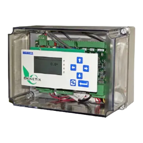
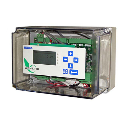
MERRICK MC3 User manual

R:\MANUALS\ENGLISH\MC3\2496ex_g\2496_G1.doc 08/14/01 3:57 PM/LDD
MC³ Controller
Operation and Maintenance
Manual
for the
24.96.EX.G Belt Feeder
Merrick Industries, Inc.
10 Arthur Drive
Lynn Haven, FL 32444
(850) 265-3611
Revisions

0.30B June 1996
0.30D July 1996 Added and updated texts, bitmaps and drawings.
Sep 1996 Added and updated texts, bitmaps and drawings.
1.0 Nov 1996 Added and updated texts, bitmaps and drawings for batch mode.
Jan 1997 Corrected text.
DAugust 1998 Added and updated text and bitmaps.
GAugust 2001 Updated version
PROPRIETARY NOTE
The information in this manual, including technical data and copies of drawings, embodies
information proprietary to Merrick Industries, Incorporated. This manual is provided to the user of
equipment purchased from Merrick Industries, Inc. for use only in operation or maintenance of
such equipment. Such information in this manual is not to be used, disclosed, copied, or
reproduced in whole or part for any use other than that indicated above, or for any other purpose
detrimental to the interests of Merrick Industries, Inc. Patents owned by Merrick Industries, Inc.
have been issued or are pending on at least some of the information in this manual, and
unauthorized use of this subject matter of such patents is a violation of such patents and is
prohibited

MC³ 24.96.EX O&M Manual Page i08/14/01 4:34 PM
INTRODUCTION...........................................................................................................................................1
SAFETY.....................................................................................................................................................1
In General..............................................................................................................................................1
Electrical Precautions............................................................................................................................1
MANUAL CONVENTIONS........................................................................................................................1
Buttons..................................................................................................................................................1
Screens.................................................................................................................................................2
SOLVING PROBLEMS .............................................................................................................................2
Help Button............................................................................................................................................2
Technical Support.................................................................................................................................2
SYSTEM CONCEPTS...................................................................................................................................3
HARDWARE .............................................................................................................................................3
Enclosure..............................................................................................................................................3
Backplane Board ..............................................................................................................................4
Card Stack Assembly............................................................................................................................4
CPU Board........................................................................................................................................4
PCAD Board.....................................................................................................................................4
PCIO Board ......................................................................................................................................4
LTI Board..........................................................................................................................................4
Power Supply Assembly........................................................................................................................4
Display Assembly..................................................................................................................................5
LCD Board........................................................................................................................................5
LCD Display......................................................................................................................................5
Touch Keypad...................................................................................................................................5
SOFTWARE..............................................................................................................................................5
Application Software..............................................................................................................................5
BIOS......................................................................................................................................................5
Register Database ................................................................................................................................5
GETTING STARTED.....................................................................................................................................6
INSTALLATION.........................................................................................................................................6
Panel Mount..........................................................................................................................................6
Installation.........................................................................................................................................6
Wall Mount............................................................................................................................................6
Installation.........................................................................................................................................6
STARTING THE CONTROLLER..............................................................................................................6
PASSWORD PROTECTION.....................................................................................................................7
MAIN SCREENS.......................................................................................................................................7
Changing Main Screens........................................................................................................................7
Feeder Screen ......................................................................................................................................7
Graph Screen........................................................................................................................................8
Numerical Display.................................................................................................................................9
ENTERING NEW VALUES.......................................................................................................................9
Numeric Entry Screen...........................................................................................................................9
Sub Menus..........................................................................................................................................10
Common Displays in Main Screens....................................................................................................10
Speed..............................................................................................................................................10
Setpoint...........................................................................................................................................10
Feedrate .........................................................................................................................................10
Belt Load.........................................................................................................................................10
Sub-Total........................................................................................................................................10
Total................................................................................................................................................10
Date and Time................................................................................................................................10
Pulses.............................................................................................................................................10
Output.............................................................................................................................................10
Deviation.........................................................................................................................................10
Blank Button ...................................................................................................................................11

MC³ 24.96.EX O&M Manual Page ii 08/14/01 4:34 PM
Setpoint...............................................................................................................................................11
LOGO..................................................................................................................................................11
Start, Stop, Clear Batch.......................................................................................................................11
Indicators ( on Feeder Screen) ...........................................................................................................11
General Alarms...................................................................................................................................12
Belt Load Over Limit.......................................................................................................................13
Belt Load Under Limit.....................................................................................................................13
PCAD Near Zero.............................................................................................................................13
PCAD Near Full ..............................................................................................................................13
Z Track Out Of Range....................................................................................................................13
PCAD Discrepancy.........................................................................................................................13
Tachos Do Not Comply...................................................................................................................13
Communications Lost.....................................................................................................................13
Setpoint Out Of Range ...................................................................................................................13
No Speed Detected ........................................................................................................................14
Anain Out Of Range .......................................................................................................................14
LCD Not Responding......................................................................................................................14
No Data From PCAD......................................................................................................................14
CONTROLLER MODES..........................................................................................................................14
SETPOINT ..............................................................................................................................................15
Setpoint Screens.................................................................................................................................15
Batch setpoint......................................................................................................................................15
Local ...............................................................................................................................................15
Remote Serial.................................................................................................................................15
Setpoint...........................................................................................................................................15
Batch Parameters...........................................................................................................................15
Feedrate .........................................................................................................................................16
Feedrate setpoint ................................................................................................................................16
Manual Speed.................................................................................................................................16
Local ...............................................................................................................................................17
Remote Analog Input......................................................................................................................17
Remote Analog Ratio......................................................................................................................17
Remote Serial.................................................................................................................................17
Snap Button....................................................................................................................................17
Setpoint Button ...............................................................................................................................17
Fallback Setpoint.................................................................................................................................18
Common Setpoint buttons...................................................................................................................18
Accept Button .................................................................................................................................18
Arrow Buttons .................................................................................................................................18
Return Button..................................................................................................................................18
ACTIONS ................................................................................................................................................18
Cal.......................................................................................................................................................18
Reset Total..........................................................................................................................................18
Sub-Total.............................................................................................................................................19
Clean Screen.......................................................................................................................................19
Diagnostics..........................................................................................................................................19
Alarms.................................................................................................................................................19
Print.....................................................................................................................................................19
Print Line Editing and Printout Selection.............................................................................................19
PF buttons. .....................................................................................................................................20
SETTING UP YOUR CONTROLLER..........................................................................................................21
SETUP ....................................................................................................................................................21
CHAIN EZ SETUP...................................................................................................................................21
WEIGHT EZ SETUP...............................................................................................................................22
CUSTOM SETUP....................................................................................................................................23
SETUP SCREEN 1 .................................................................................................................................24
Units Select.........................................................................................................................................24

MC³ 24.96.EX O&M Manual Page iii 08/14/01 4:34 PM
List of Unit String Combinations .....................................................................................................24
Decimal Points ....................................................................................................................................25
Design Capacities ...............................................................................................................................25
PID Parameters & Output Dynamic Protection...................................................................................25
Gain ................................................................................................................................................26
Integral............................................................................................................................................26
Derivative........................................................................................................................................26
SCR Accel %/s and SCR Decel %/s...............................................................................................26
Start Speed.....................................................................................................................................26
Limit Switches .....................................................................................................................................26
FeedRate HI/LO..............................................................................................................................27
Feedrate Rel Dev............................................................................................................................27
Feedrate Setpoint Deviation ...........................................................................................................27
Numeric Parameters.......................................................................................................................27
Belt Parameters ..................................................................................................................................28
Pulses / Rev....................................................................................................................................28
Length.............................................................................................................................................28
# Proc Revs ....................................................................................................................................28
# Speed Revs .................................................................................................................................28
Nominal Speed...............................................................................................................................28
Alarm Delay....................................................................................................................................28
Zero Tracking Parameters..................................................................................................................28
Wait Time .......................................................................................................................................29
Max Load........................................................................................................................................29
Max Step Alwd................................................................................................................................29
Max Z Track....................................................................................................................................29
Tachometer Parameters.....................................................................................................................29
Type................................................................................................................................................29
Mode...............................................................................................................................................30
Speed Sensing Operational Mode..................................................................................................30
Numeric Parameters.......................................................................................................................31
Setpoint...............................................................................................................................................31
Totalizer Cut-Off..................................................................................................................................31
Calibration Parameters .......................................................................................................................31
Calibration Weight ..........................................................................................................................31
E-Cal Liveload.................................................................................................................................31
Weigh Span....................................................................................................................................31
Chain Load......................................................................................................................................31
Calibration Speed ...........................................................................................................................31
Display Dampening.............................................................................................................................32
SETUP SCREEN 2 .................................................................................................................................33
Analog Inputs ......................................................................................................................................33
IN1 Zero Level / IN2 Zero Level......................................................................................................33
IN1 100% Level / IN2 100% Level..................................................................................................33
IN1 Scaling / IN2 Scaling................................................................................................................33
Analog Outputs....................................................................................................................................33
Mode...............................................................................................................................................34
Type................................................................................................................................................34
Digital I/O Mapping..............................................................................................................................34
Mapping inputs................................................................................................................................35
Mapping outputs .............................................................................................................................35
Inverting inputs and outputs............................................................................................................35
Forcing inputs and outputs .............................................................................................................35
Available logical I/O points..............................................................................................................36
External physical I/O points ............................................................................................................36
Digital Inputs Setup.........................................................................................................................36
TAB.................................................................................................................................................36
INV (button) / RV (indication)..........................................................................................................37

MC³ 24.96.EX O&M Manual Page iv 08/14/01 4:34 PM
FRC (button) / FC (indication).........................................................................................................37
List of Logical Inputs.......................................................................................................................37
List of Physical Inputs.....................................................................................................................38
Default Input Mapping.....................................................................................................................39
Digital Outputs ................................................................................................................................40
INV (button) / RV (indication)..........................................................................................................40
FRC (button) / FC (indication).........................................................................................................40
TAB.................................................................................................................................................40
List of Logical Outputs....................................................................................................................41
List of Physical Outputs ..................................................................................................................42
List of Default Output Settings........................................................................................................43
Sample Rate .......................................................................................................................................43
Internal Sample Rate Parameters ..................................................................................................43
External Sample Rate Parameters.................................................................................................44
External Totalizer Parameters.............................................................................................................44
Divide Value....................................................................................................................................44
Pulse Length...................................................................................................................................44
Communications .................................................................................................................................44
Baud Rate.......................................................................................................................................44
Data Bits .........................................................................................................................................45
Stop Bits..........................................................................................................................................45
Parity...............................................................................................................................................45
Numeric Parameters...........................................................................................................................45
Controller Number ..........................................................................................................................45
Comp Start Code............................................................................................................................45
Comp End Code.............................................................................................................................45
Communication Time-out ...............................................................................................................45
Set Date and Time..............................................................................................................................46
PCAD Settings ....................................................................................................................................46
CAL.................................................................................................................................................46
ZERO..............................................................................................................................................46
GAIN...............................................................................................................................................46
Set Status .......................................................................................................................................46
Number of PCAD’s .........................................................................................................................46
Allowed Difference..........................................................................................................................46
Display Parameters.............................................................................................................................47
CALIBRATING YOUR CONTROLLER........................................................................................................48
INITIAL CALIBRATION CHECKLIST......................................................................................................48
CALIBRATION MENU.............................................................................................................................48
Speed Calibration................................................................................................................................49
Zeroing Procedure ..............................................................................................................................50
Material Calibration .............................................................................................................................51
Scale Totalized ...............................................................................................................................51
Actual Total.....................................................................................................................................51
Chain Procedure.................................................................................................................................52
Chain Factor Procedure......................................................................................................................53
Weight Procedure...............................................................................................................................53
Weight Factor Procedure....................................................................................................................54
Electronic Calibration ..........................................................................................................................54
E-Cal Factor Procedure ......................................................................................................................55
Grab Sample Calibration.....................................................................................................................56
Analog Input Setup and Calibration.....................................................................................................56
DIAGNOSING PROBLEMS.........................................................................................................................58
DIAGNOSTIC MENUS............................................................................................................................58
PCAD Diagnostics...............................................................................................................................58
Ld....................................................................................................................................................58
Out %..............................................................................................................................................58

MC³ 24.96.EX O&M Manual Page v08/14/01 4:34 PM
PCAD1 and PCAD2........................................................................................................................58
LL....................................................................................................................................................58
Abs..................................................................................................................................................58
Cnts ................................................................................................................................................59
Z Ld.................................................................................................................................................59
Settings...........................................................................................................................................59
Scale Factor....................................................................................................................................59
Communication Diagnostics................................................................................................................59
Rx Buffer.........................................................................................................................................59
Tx Buffer.........................................................................................................................................59
Error Counters................................................................................................................................59
IIR -.................................................................................................................................................60
LSR -...............................................................................................................................................60
TX -.................................................................................................................................................60
RX -.................................................................................................................................................61
Communication Parameters...........................................................................................................61
Tacho Diagnostics...............................................................................................................................61
EMT PULS......................................................................................................................................61
PT ...................................................................................................................................................61
TST.................................................................................................................................................61
Blt Trvl.............................................................................................................................................61
Curr ratio.........................................................................................................................................61
Diff %..............................................................................................................................................61
Analog I/O Diagnostics........................................................................................................................62
Digital I/O Diagnostics.........................................................................................................................62
Register Monitor..................................................................................................................................62
Register Editor.....................................................................................................................................63
Advanced Setup..................................................................................................................................63
Quick Setup.........................................................................................................................................63
SOLVING PROBLEMS ...........................................................................................................................64
Unit does not power up .......................................................................................................................64
Controller Fails to Boot Up..................................................................................................................64
LCD Display too dark or too light.........................................................................................................65
No load, or bad Load Reading ............................................................................................................65
Tacho not counting pulses, or no speed indication............................................................................65
No analog Input...................................................................................................................................65
External Totalizer problems ................................................................................................................65
General Alarms...................................................................................................................................65
No Serial Communications..................................................................................................................66
Hang Message Appears......................................................................................................................66
HARDWARE CALIBRATION AND TESTING.........................................................................................66
Analog Outputs....................................................................................................................................66
Analog Inputs ......................................................................................................................................66
PCAD ..................................................................................................................................................67
Simulator.............................................................................................................................................67
WORKING WITH INPUTS AND OUTPUTS ...............................................................................................68
LTI BOARD .............................................................................................................................................68
EMT.....................................................................................................................................................68
Tacho..................................................................................................................................................68
Serial Communications.......................................................................................................................68
PCIO BOARD..........................................................................................................................................69
Digital I/O.............................................................................................................................................69
Digital Inputs...................................................................................................................................69
Digital Outputs ................................................................................................................................69
Analog I/O ...........................................................................................................................................69
Analog Inputs..................................................................................................................................69
Analog Outputs...............................................................................................................................70

MC³ 24.96.EX O&M Manual Page vi 08/14/01 4:34 PM
PCAD BOARD.........................................................................................................................................70
KEYBOARD LOCATION CODES...........................................................................................................70
PRINTER PORT......................................................................................................................................70
STORAGE...................................................................................................................................................71
STORAGE ON RECEIPT FROM FACTORY..........................................................................................71
Storage Longer than 6 Months............................................................................................................71
Storage up to 6 Months.......................................................................................................................71
STORAGE FOLLOWING USE................................................................................................................71
OPERATION AFTER STORAGE............................................................................................................71
SPARE PART LIST .....................................................................................................................................72
MC³ CONTROLLER SPARE PARTS LIST.............................................................................................72
ACCESSORIES FOR THE MC³ CONTROLLER....................................................................................72
I/O System...........................................................................................................................................72
Spare I/O Plugs...................................................................................................................................72
Miscellaneous......................................................................................................................................72
Feeder Connection..............................................................................................................................73
APPENDIX A ...............................................................................................................................................74
MC³ PANEL MOUNT - DIMENSIONS.....................................................................................................74
WALL MOUNT - DIMENSIONS.............................................................................................................75

MC³ 24.96.EX O&M Manual Page 108/14/01 4:34 PM/LDD
INTRODUCTION
SAFETY
The Merrick MC³ Controller is used for the monitoring and control of process weighing equipment.
To insure personnel safety please read the following instructions and precautions carefully.
In General
1. Observe all standard precautions that pertain to moving machinery.
2. Observe all standard precautions that pertain to electrical drives and electrical controls.
3. Pay particular attentions to special notes and precautions that appear throughout this
manual.
4. Please read and familiarize yourself with this entire manual before attempting service or
repair of the Merrick MC³ Controller. If you have any questions or problems please call
the Merrick Service Department for assistance.
Electrical Precautions
1. Before undertaking work on the electrical system, the drives, or the Controller, open
main disconnect switches and lock boxes. Work should never be performed on the
Controller with power on the unit. It is recommended to disconnect the power cord from
the panel mount style controller or switch off the main power in a wall mount before
attempting any service procedure.
2. Verify that all grounds that are called for on the wiring diagrams are in place and are
securely connected. Proper grounding not only helps insure your personal safety, but
also is necessary for the proper operation of the controller.
3. If it is necessary that you must work in or near areas of live high voltage always keep
one hand clear of the machine, the cabinet, or any other conductors to avoid the
possibility of electrical shock traveling across your chest. NEVER undertake any
electrical work in areas with wet or flooded standing areas.
4. NEVER impair or disable the function of a fuse.
IF YOU ARE IN DOUBT ABOUT ANY PROCEDURE, CONTACT THE MERRICK SERVICE
DEPARTMENT. SEE Technical Support ON PAGE 2
MANUAL CONVENTIONS
NOTE: Any additional information that may be useful follows the note marker.
CAUTION: Be careful, certain settings may cause problems.
WARNING: Follow the directions prescribed in the warning. Serious problems can occur if the
recommendations are not followed.
Buttons Button graphics will be shown to the left of the corresponding information regarding the
function for the button.

MC³ 24.96.EX O&M Manual Page 208/14/01 4:34 PM/LDD
Screens
A graphic of this size and type will show the functions available and/or information available in
diagnostic screens and special display screens.
SOLVING PROBLEMS
Several methods are available for use to assist in solving problems. The application contains help
buttons for giving text explanations of the current selected function or parameter. Also included in
this manual is a troubleshooting section to assist in solving technical problems (Diagnosing
Problems, page 58).
Help Button
If you do not understand a procedure or parameter this button is available to give some
guidance.
Technical Support
Merrick provides customer technical and spare part support 24 hours a day, seven days a week.
Our normal business hours are Monday through Friday 7:30 AM until 4:30 PM Central Standard
Time. During normal hours call 1-888 MERRICK ( 637-7425) extension 7811.
After normal hours and on holidays and week-ends, technical assistance is available by calling 1-
888 MERRICK extension 7878. Follow the instructions and be sure to enter the area code and the
phone extension where you can be reached. Someone will return your call as soon as possible.
When you call Merrick for Technical Support, please have your machine serial number or a
controller serial number. This information will better help us to serve you.

MC³ 24.96.EX O&M Manual Page 308/14/01 4:34 PM/LDD
SYSTEM CONCEPTS
HARDWARE
MC
3
Controller Unit
Touch
Screen
LCD
Interface
Board
LCD
Display
LTI
PCIO
Inputs
and
Outputs
PCAD
Load
Cell
Interface
CPU
Display Assembly
Ribbon Cable
Card Stack
Power
Supply
Power
Recepticle
Power System
Load Cells
Backplane
Board
PC-104 Bus
2nd PCAD 2nd PCIO
IBM PC or
Compatible
ASCII Serial Printer
EMT (AC or DC)
Electromechanical
Totalizer
I
O
SCR Motor
Controller
I
O
I
O
Speed Encoder
Speed Encoder
Alarms
Infeed Gate for
Batching
Optional Feeder
Connection Board
LCD Tacho
Input
The MC³ Controller has been designed to control many different types of feeding, weighing and
metering equipment. This allows for easier maintenance and simplified training.
The Standard Merrick MC³ 24.96.EX Controller consists of an Enclosure, an LCD Display, Card
Stack and a Power Supply.
Enclosure
Panel Mount
The panel mount enclosure consists of a rectangular box with a hinged door on the rear covering
the I/O connections, a removable top cover, a system grounding bar and a sliding tray. The slide
tray allows the Card Stack Assembly to be slid out of the back of the enclosure for easier
maintenance while the controller is mounted into a panel. The Display assembly is mounted on the
front bezel. The top cover may be removed for easier access to the boards. Access to the
terminal blocks for interconnection with other equipment is obtained by unscrewing the rear cover.
Wall Mount
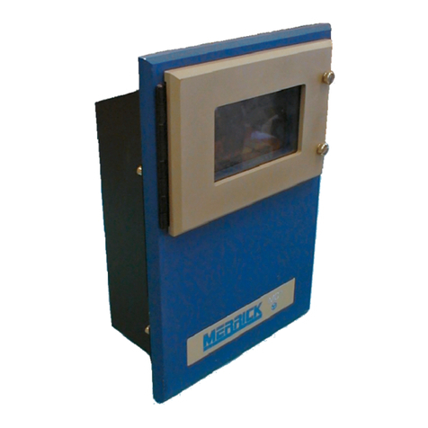
The wall mount enclosure is available in NEMA-4 or NEMA-12 boxes. NEMA-4 box includes
gaskets and a window kit over the touch screen to provide extra protection.

MC³ 24.96.EX O&M Manual Page 408/14/01 4:34 PM/LDD
Backplane Board
Most of the Digital I/O connections to the MC³ will be made through the Backplane Board. The
Backplane mounts vertically in the rear access cover on the Panel mount type enclosure. On the
Wall mount enclosure, the boards are mounted directly below the Card stack assembly. The
boards can also be mounted onto a DIN rail away from the controller. The Backplane Board has 7
output relays and 4 input connectors and allows connection to one I/O rack on the PCIO card. This
board connects to the PCIO card via a ribbon cable.
Additional Backplane boards may be connected using a DIN rail as the mounting for the boards.
Up to four Backplane boards may be connected to the MC³ Controller when two PCIO boards are
in the card stack assembly.
Card Stack Assembly
The Card Stack assembly consists of a CPU Board, one or two PCAD boards, one or two PCIO
boards and an LTI board. The Card Stack Assembly in the panel mount enclosure is mounted to
the slide tray and is kept in place by a pair of guides that are permanently mounted onto the
enclosure and catch screws on the back of the enclosure. In the wall mount enclosure the Card
Stack Assembly is securely attached to the mounting plate. All boards are connected electronically
by way of an industry standard PC-104 interface bus.
CPU Board
The CPU Board contains the Intel 386EX Microprocessor. It also contains associated support
circuitry for a bus interface, serial interface and memory support. The CPU board is the bottom
board of the card stack.
PCAD Board
The Load Cell Transducer A/D Board (PCAD) contains the circuitry needed to process an input
from load cells into digital data. The Analog to Digital Converter used on the PCAD Board is a 20
bit converter. This allows the Analog Load Cell signal to be resolved into approximately 1,000,000
digital counts. As an option, the 2496EX Controller has the ability to utilize two PCAD boards.
There are no switches on the PCAD Board for setting parameters such as Gain, Zero Offset or
Electronic Calibration. The PCAD Board contains specialized circuitry for dynamically adjusting
these parameters through software. There is one set of jumpers to select Zener Barrier Protection
and Normal Operation of the PCAD.
PCIO Board
The PCIO Board provides the circuitry for two isolated analog outputs, one isolated analog input,
16 digital outputs and 8 digital inputs. The standard MC³ 2496EX Controller comes with one PCIO
board. One additional PCIO Board is available as an option giving the controller a capability of
having four isolated Analog Outputs, two isolated Analog Inputs, 32 Digital outputs and 16 Digital
inputs. There are two racks of inputs and outputs per PCIO board. Each rack consists of 7
outputs and 4 inputs. Each rack is connected to a Backplane board via a ribbon cable.
LTI Board
The LTI (LCD Tachometer Input) Board contains the circuitry required to process incoming speed
pulses from one or two Tachos, outputs for an AC and DC Electromechanical Totalizer (EMT), an
isolated RS-485 Serial Port and an interface to the Display assembly.
The RS-485 Serial Communications port is a feature which provides the circuitry necessary for the
MC³ Controller to communicate with other serial devices such as a SuperBridge or Personal
Computer. For more information on MC³ Serial Communications see [1] This specification lists
some hardware options and interconnection examples and also describes the Merrick
Communications Protocol in detail.
Power Supply Assembly
The Power Supply Board provides the proper voltages to the MC³ for operation. The Power
Assembly consists of the Power Supply, Power Receptacle and an AC and DC power cables. The
Power Supply is mounted on the front of the slide tray.

MC³ 24.96.EX O&M Manual Page 508/14/01 4:34 PM/LDD
Display Assembly
The Display Assembly consists of a Touch Keypad, an LCD Board and an LCD Display.
LCD Board
This board is used to interface the LCD Display and the Touch Keypad to the LTI Board and
provides the proper voltage for the back light of the LCD Display. There is a potentiometer for
adjusting the contrast of the LCD Display. Also on specific LCD Boards containing an LS220 type
inverter there is a Brightness Adjust potentiometer.
LCD Display
The LCD Display is a 240 horizontal by 128 vertical pixel resolution monochrome graphical display.
The display works in conjunction with the Touch Screen to provide a Graphical User Interface.
Touch Keypad
The Touch Keypad is mounted directly to the bezel of the MC³ Controller. It consists of a four row
by eight column touch cell array. The Touch Keypad works with the LCD Display to provide a way
for you to interface with the controller.
SOFTWARE
The MC³ software consists of three primary parts: The BIOS (Basic Input / Output System), a
register database, and the actual application software. The application and database is specific for
the 24.96.EX controller. The BIOS is common for many different applications.
Application Software
Application Software is written for each specific type of “job” that the controller is to perform.
This software will allow you to turn on and off different modes of operation which allows you to
configure the software for your specific process
There are four modes of operation of this software package:
Belt Scale – Basic model measuring the belt load and speed and calculates the feedrate
and totalizes.
Batching Belt Scale – Allows you to batch out predefined lots of material across the belt.
Feeder – The MC³ controls the speed of the belt or pre-feeding device to follow a feedrate
setpoint.
Batching Feeder – Allows you to batch out material at specific feedrates controlled by the
MC³. There is a feedrate setpoint and a batch setpoint.
BIOS
The BIOS is the portion of the software which directly manipulates the hardware. It is the interface
between the application and the hardware.
Register Database
The Register Database is a set of variables used in the software application. It is provided to allow
structured access through Serial Communications to variables used in the MC³. A numeric listing
of registers for each application is available from Merrick. Procedures for using Serial
Communications to access the register list are also provided in [1].

MC³ 24.96.EX O&M Manual Page 608/14/01 4:34 PM/LDD
GETTING STARTED
INSTALLATION
Please refer to your wiring diagrams to insure proper installation of the controller. If you need to
change the wiring from the supplied wiring diagrams, Merrick must first be consulted to insure safe
and proper operation of the controller. See Technical Support on page 2for contacting the Merrick
Technical Service department.
Panel Mount
The Merrick MC³ Panel Mount Controller is designed for mounting in the control panel. It is
suitable for use in environments that are generally clean, and within the temperature range of 32o
to 122oF (0oto 50oC). It must be protected from water and dust.
Installation
1. Carefully unpack the controller and inspect it for obvious damage as a result of shipping
or handling. If the unit has been stored for a long period (greater than one month), a
more thorough inspection of the unit is recommended. If the unit appears to be
damaged in any way, contact the Merrick Service Department for assistance.
2. Mount the controller in your panel, following the instructions on the drawing in “MC³
Panel Mount - DIMENSIONS” on page 74. Make sure there is adequate clearance
around the unit for maintenance and ventilation.
3. Insure that the Power Cord is disconnected from the Power Receptacle at the rear of
the controller. Make the wiring connections to the controller, following the instructions
on your electrical connection diagram.
4. Verify all wiring connections before re-installing the Power Cord and applying power to
the unit.
Wall Mount
The Merrick MC³ Wall Mount Controller is designed to be weatherproof, and can generally be
mounted anywhere where the temperature range is within -10oto 40o C. Merrick recommends
that it be located out of direct sunlight and away from dripping water.
Installation
1. Carefully unpack the controller and inspect it for obvious damage as a result of shipping
or handling. If the unit has been stored for a long period (greater than one month),
inspect the unit for rust or corrosion. If the unit appears to be damaged in any way,
contact the Merrick Service Department for assistance.
2. Mount the controller on a vertical surface. Make sure there is adequate clearance
around the unit for swinging open the door and for maintenance.
3. Make the wiring connections to the controller. In order to maintain the weatherproof
integrity of the Wall Mount enclosure, you must use liquid-tight conduit and conduit
connectors when running your wires. It is recommended to penetrate the enclosure
from the bottom.
4. Verify all wiring connections before applying power to the unit.
STARTING THE CONTROLLER
The following is an overview of the actions necessary for proper installation of the MC³ controller.
Each step should be completed before the controller is placed in operation. Steps 3 through 7 may
be substituted by performing either Chain EZ Setup (page 21) or Weight EZ Setup (page 22)
procedure.

MC³ 24.96.EX O&M Manual Page 708/14/01 4:34 PM/LDD
1. Check all your wiring. At least the load cell(s) and power have to be connected for the
controller to work. Normally, a connection diagram is supplied. Read more about inputs
and outputs in the “Working With INPUTS AND OUTPUTS” on page 68.
2. Power up your controller. During power up several start up operations are being
performed. This sequence takes approximately twenty seconds. The start up screen
counts down the time remaining during the start up sequence. Check for any error
messages during the power-up sequence.
3. Check the Calibration settings. Normally, a specification sheet is supplied. Read more
about how to set the Calibration parameters in the “Setting UP Your Controller” section
on page 21.
4. Run a Speed Calibration procedure. Refer to “Speed Calibration“ on page 49 for more
information.
5. Run a Zero procedure. See “Zeroing Procedure” on page 50.
6. Run either a Chain, Weight or an Electrical Calibration. See “Chain Procedure” (page
52), “Weight Procedure“ (page 53) or “Electronic Calibration” (page 54) for the method
for performing the calibration procedures.
7. Set the Limit Switch values for the application. See Limit Switches on page 26.
8. Program the Setpoint method to be used by your application. See “Setpoint” on page
15.
9. Record all essential parameters for your reference. Use a copy of the specification
sheet.
10. Change the Calibration, Diagnostic and Setup passwords to protect your settings.
PASSWORD PROTECTION
The Password Entry screen is used to provide protection of the settings in the Calibration, Setup,
and Diagnostic screens MC³ controller. The password is a four digit number, and can be different
for each of the three screens. The default password for access to the Calibration Screen is 1234.
The default password for the Setup screen is 5678. The default Diagnostic Screen password is
1030. The Password Edit Screen is used to select the passwords that allow specific users access
to the Screens. To change the existing passwords, or to turn off password protection, navigate to
the Password Edit screen (press ACT, DIAG, and then PASSWORD), and enter a new four-digit
password for the screen. Entering a ‘0’ in the password field will turn off password protection for
the screen.
MAIN SCREENS
Changing Main Screens
The is used to change between the Feeder Screen, Graph Screen and a Numerical Display.
Feeder Screen
The first main screen in the 24.96.EX Controller is the Feeder Screen. This screen is setup to
show you the current running status of the controller. It also allows you to enter into sub menus for
setting the controller parameters, calibration and other functions.

MC³ 24.96.EX O&M Manual Page 808/14/01 4:34 PM/LDD
Feeder Screen
Graph Screen
A Graph screen is available to show trend information. This screen also displays the current
running status of the controller.
Graph Screen
IDLE
,."
Iblft
QY
".
'otch:
0.0
Ib
""
AM
]~mum/
~I,::'
SP:
SO."
lb/"u"
LD:
7."
Iblft
SPD:
7.2
ftl"u"
FR:
SO."
Ibl"u"
"
'1"1%
S,b-T:
'90
Ib
Toto):
'90
Ib

MC³ 24.96.EX O&M Manual Page 908/14/01 4:34 PM/LDD
Numerical Display
A large font screen is also available to display the current running status of the controller in a larger
typeface for easier viewing from a distance.
Numerical Display
There are several common elements to the screens which are described below.
ENTERING NEW VALUES
Numeric Entry Screen
Numeric Screen Example
Most values are entered into the Controller via a numeric entry screen (see the above example).
This screen shows the name of the parameter, the current value, units and the minimum and
maximum allowed values for the parameter. If there are three or more related parameters, the
controller displays three at a time, otherwise the controller will only show one parameter. The
active parameter is enclosed in a rectangle. This is the value that any button entry will act upon.
First find the value by using the Up or Down arrow buttons to scroll to the parameter to be
changed.
Enter the new value for the selected parameter using the numeric buttons. The display will show
the value area as they are entered.
If the value is correct press the [ENT] button to save this value. The controller tests the number to
insure that it is a valid entry. If the number is within the minimum and maximum values a message
will appear under the parameter list:
“Parameter Accepted”
If the value is incorrect, there are two ways to correct the number. One is to press the [CLR] button
and re-enter the value. You may also use the Back arrow button to move back to the incorrect
digit. If the value is not within accepted limits, the following message will appear:
“Value is Out of Range”
NOTE: The unit will be shown for the parameter being displayed.

MC³ 24.96.EX O&M Manual Page 10 08/14/01 4:34 PM/LDD
Sub Menus
The button allows access to the setup menu system which includes the EZ Setup functions
and the Custom Setup menus (see Setting UP Your Controller on page 21 for more information).
The button (page 18) allows access to the calibration, total and subtotal reset and diagnostic
menus. A password will need to be entered to allow access to the menus if Password protection is
enabled. See PASSWORD PROTECTION on page 7.
Graph Update Time
In the Graph screen the and buttons change the update time of the graph. The update
time ranges from 1 to 60 seconds in one second increments and is displayed above the graph.
Common Displays in Main Screens
Speed
This is the current belt speed value in the current engineering units for speed. (SPD:) See Units
Select on page 24.
Setpoint
This is the value of the current setpoint in units based on the type of setpoint method selected. If
Batch mode and PID mode are enabled or Batch mode only is enabled the current batch setpoint
will be displayed. If PID mode only is enabled the feedrate setpoint method and value will be
displayed. If both Batch and PID are disabled neither setpoint will be displayed. More information
on Setpoint, see page 15.
Feedrate
This is the Current Feedrate in current units for feedrate. (FR:)
Belt Load
This is the current belt load value in the engineering units for load. (LD:)
Sub-Total
This is the sub-total value for the feeder. See Page 19 for instructions on the procedure to reset the
Sub-Total. (Sub-T:)
Total
This is the master total for the feeder. The Master Total may be reset from the Reset Total button
in the Actions menu. See Page 19 for instructions on the procedure to reset the Master Total.
Date and Time
The Date and Time is available on all of the main screens.
Pulses
This value is the number of pulses accumulated in the controller for Tacho 1. This value is
available only in the Numeric Display.
Output
This is the current control output (belt speed demand) value in percentage. This value is available
only in the Large Font Display.
Deviation
This is the percentage of difference between setpoint and feedrate. This value is available only in
the Numeric Display.

MC³ 24.96.EX O&M Manual Page 11 08/14/01 4:34 PM/LDD
Blank Button
This button places a empty line on the screen.
Setpoint
Based on the mode of the controller this button will allow you to enter the Batch or Feedrate
setpoint. If the mode is Batching Feeder both Batch and Feedrate setpoint methods are available
from this button. See Setpoint on page 15 for more information.
LOGO
This screen displays the address and phone number for Merrick.
It also shows the revision and build date for the software that is currently in operation. The version
and build date are important when you need service on your controller.
Start, Stop, Clear Batch
These buttons allow you to start, stop, or clear a batch. The buttons will only be visible
when Batch Controls is enabled. See Digital Inputs Setup on page 36. The batch will run until the
batch total has reached the batch setpoint, and the load has dropped below 3% of the design load.
Start batch starts a batch process. It will turn on the Discharge Gate logical output.
When the batch total has reached the batch setpoint minus the Preact value has been
reached, the Discharge Gate logical output will turn off. (see Batch Parameters on page
15 for more information).
Stop batch pauses a batch process. It will turn off the Discharge Gate logical output.
The batch may be restarted by touching the start batch button. The batch may also be
cleared by touching the clear batch button.
Clear Batch stops the current batch process clears the batch total and turns off the
Discharge gate logical output.
Indicators ( on Feeder Screen)
There are indicators which are used by the software to provide you with a visual
indication that the controller is operating properly. The operator can insure that the
controller is in the correct mode and accomplishing its set tasks by being aware of which
visual indicators are (ON) or (OFF).
HI High Feedrate - This indicator is on when a high feedrate condition exists.
The type and value of High Limit Switch is determined by the operator. When
this indicator is off the feedrate is not above the parameters set in Limit

MC³ 24.96.EX O&M Manual Page 12 08/14/01 4:34 PM/LDD
Switches (page 26).
GOOD Good. This indicator is on when all of the following conditions have been met. If any
one of the conditions are not met this indicator will not activate.
1. The setpoint method is not Manual Speed.
2. The Feeder Block input is OFF (see Digital Inputs Setup on page 36).
3. The Run Permission input is ON (see Digital Inputs Setup on page 36).
4. The controller is in Gravimetric Mode (see Digital Inputs Setup on page 36).
5. No Calibration procedures are running.
6. The controller is not in its power up sequence.
7. Feeder Run output is ON.
8. The PID controller algorithm output is in its active domain.
9. There are no General Alarms.
10. The Feedrate has not exceed the Hi Feedrate Limit or Low Feedrate Limit.
LO Low Feedrate - This indicator is on when a low feedrate condition exists. The type and
value of Low Limit Switch is determined by the operator. When this indicator is off the
feedrate is not below the value set in Limit Switches (page 26).
RMT Remote - This indicator is on when the keypad has been locked through serial
communications. For more information on MC³ Serial Communications see [1]. The
remote device may be SuperBridge or another MC³. This indicator is off during normal
keypad operation.
AUTO Auto - When this indicator is on, the controller is in the Automatic Setpoint Control
Mode. This is active when a Setpoint mode other than Manual Speed is active. If the
controller is in Manual Setpoint the indicator will be off. See Page 15 for a complete
explanation of the Setpoint modes
RPER Run Permission - This indicator will be on when the Logical Input Run Permission is
ON. Run Permission clamps the speed demand output from the controller to Zero
when OFF. With this input ON the controller is able to control the process (see Digital
Inputs Setup on page 36).
GRAV Gravimetric ON - This indicator follows the Logical Input Gravimetric ON. (see Digital
Inputs Setup on page 36).
ZTRK Zero Tracking - This indicator will be on when Zero Tracking is turned on and the
procedure is currently running. See Zero Tracking Parameters on page 28 for more
information.
FBLK Feeder Block - This indication follows the Logical Input ‘Feeder Block’. See Digital
Inputs Setup on page 36 for more information.
General Alarms
The general alarm button is used to indicate that a problem may exist. This button will
remain on until the conditions that caused the alarm have been removed and the alarm
acknowledged. To view the condition (or conditions) which has caused a General Alarm,
touch the alarm button. All alarms will be displayed with an indicator to the left of the text ( = ON
= OFF). You may still access this screen from the action menu.
Other manuals for MC3
1
Table of contents
Other MERRICK Controllers manuals
Popular Controllers manuals by other brands

Westfalia
Westfalia 98 37 61 Notes on installation and operation

Chore-Time
Chore-Time 28999 user manual

Spirax Sarco
Spirax Sarco LC2610 Installation and maintenance instructions
Dahua
Dahua DHI-ASC1204C user manual

Vestax
Vestax VCI-100MKII owner's manual

Will Burt
Will Burt PositionIt PI-75 Operator's manual
