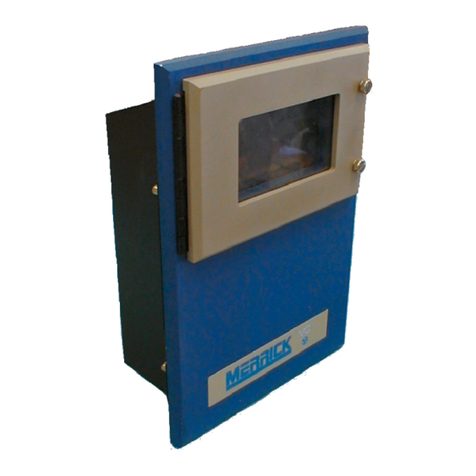
MERRICK MC3 90.10.EX User manual

MC³ 90.10.EX
MasterSet Controller
Operation and Maintenance Manual
Version ß
Merrick Industries, Inc
10 Arthur Drive
Lynn Haven, FL 32444
Ph. +1 850.265.3611
Fax +1 850.265.9768
Web http://www.merrick-inc.com


Revisions
Version Date Description
Z02/06/03/ldd New
All trademarks referenced are the property of their respective owners.
PROPRIETARY NOTE
The information in this manual, including technical data and copies of drawings, embodies information proprietary to
Merrick Industries, Incorporated. This manual is provided to the user of equipment purchased from Merrick Industries, Inc.
for use only in operation or maintenance of such equipment. Such information in this manual is not to be used, disclosed,
copied, or reproduced in whole or part for any use other than that indicated above, or for any other purpose detrimental to
the interests of Merrick Industries, Inc. Patents owned by Merrick Industries, Inc. have been issued or are pending on at
least some of the information in this manual, and unauthorized use of this subject matter of such patents is a violation of
such patents and is prohibited.


MC³ 90.10.EX O&M Manual -i-
TABLE OF CONTENTS
INTRODUCTION ....................................................................................................................2
MANUAL CONVENTIONS ..........................................................................................................2
Important points...............................................................................................................2
Buttons............................................................................................................................2
Screens...........................................................................................................................2
SAFETY................................................................................................................................2
In General .......................................................................................................................2
Electrical Precautions.......................................................................................................2
Solving Problems.............................................................................................................2
Technical Support ............................................................................................................3
SYSTEM CONCEPTS ............................................................................................................4
HARDWARE OVERVIEW...........................................................................................................4
Installation.......................................................................................................................4
Enclosures ......................................................................................................................5
Electronic Cards ..............................................................................................................6
SOFTWARE OVERVIEW ...........................................................................................................8
Application Software ........................................................................................................8
BIOS...............................................................................................................................8
Register Database ...........................................................................................................8
Digital I/O Mapping...........................................................................................................8
RUNNING & CONTROLS .......................................................................................................9
INITIAL SETUP.......................................................................................................................9
MAIN DISPLAY.......................................................................................................................9
MASTER SETPOINT..............................................................................................................10
Local.............................................................................................................................10
Analog ..........................................................................................................................11
Ratio .............................................................................................................................11
Serial ............................................................................................................................11
FAULTS..............................................................................................................................12
WARNINGS .........................................................................................................................12
GRAPH SCREEN..................................................................................................................13
ACTION MENU.....................................................................................................................13
Recipe Select ................................................................................................................13
Start/Stop Feeders .........................................................................................................13
Reset Sub-Total.............................................................................................................14
Reset Master Total.........................................................................................................14
Diagnostic Display .........................................................................................................14
Settings.........................................................................................................................14
RECIPE MENU.....................................................................................................................14
Feeder Amount ..............................................................................................................15
Recipe String.................................................................................................................15
FEEDER DISPLAY.................................................................................................................15
FEEDER SETTINGS...............................................................................................................16
Feeder Numeric.............................................................................................................17
Feeder Strings ...............................................................................................................18
PRINTER MENU ...................................................................................................................19
Print Line Editing and Printout Selection ..........................................................................19
SETTINGS MENU................................................................................................................21

MC³ 90.10.EX O&M Manual -ii -
ENTERING NEW VALUES.......................................................................................................21
Units Select...................................................................................................................21
Design Capacities ..........................................................................................................22
Decimal Points...............................................................................................................22
Comm Parameters .........................................................................................................22
Comm 1 Numeric...........................................................................................................23
Comm 2 Numeric...........................................................................................................24
Limit Switches................................................................................................................24
Panel Meter...................................................................................................................25
Display Parameters........................................................................................................25
EMT Parameters............................................................................................................25
Date/Time .....................................................................................................................26
Analog Input ..................................................................................................................26
Analog Input Source Settings..........................................................................................26
Analog Input Numeric.....................................................................................................26
Analog Input Cal ............................................................................................................27
Analog Outputs..............................................................................................................28
Analog Output Cal..........................................................................................................28
DIGITAL IO .........................................................................................................................29
Digital Inputs..................................................................................................................29
Digital Outputs...............................................................................................................31
DIAGNOSING PROBLEMS ..................................................................................................34
DIAGNOSTIC DISPLAY...........................................................................................................34
Feeder Diagnostics........................................................................................................34
Analog I/O Diagnostics...................................................................................................34
Communication Diagnostics............................................................................................34
DF1 and Modbus Diagnostics.........................................................................................35
Digital I/O Diagnostics....................................................................................................35
Register Monitor ............................................................................................................36
Misc. Data.....................................................................................................................36
Faults............................................................................................................................36
Warnings.......................................................................................................................36
DIAGNOSTIC SETTINGS.........................................................................................................37
Password Settings .........................................................................................................37
Quick Setup...................................................................................................................37
Register Editor...............................................................................................................37
SOLVING PROBLEMS.........................................................................................................38
SYMPTOMS.........................................................................................................................38
Unit does not power up...................................................................................................38
Controller Fails to Boot Up. .............................................................................................38
LCD Display too dark or too light .....................................................................................38
No analog Input .............................................................................................................38
External Totalizer problems ............................................................................................38
No Serial Communications .............................................................................................38
Hang Message Appears .................................................................................................39
HARDWARE CALIBRATION AND TESTING ......................................................................39
Analog Outputs..............................................................................................................39
Analog Inputs ................................................................................................................39
CONTROLLER HARDWARE................................................................................................40
LTI BOARD.......................................................................................................................40
EMT..............................................................................................................................40
Encoder ........................................................................................................................40
Serial Communications...................................................................................................40
PCIO BOARD .....................................................................................................................41

MC³ 90.10.EX O&M Manual -iii -
Digital Inputs..................................................................................................................41
Digital Outputs...............................................................................................................41
Analog Inputs ................................................................................................................41
Analog Outputs..............................................................................................................42
LCD Board ....................................................................................................................42
CPU BOARD ......................................................................................................................42
Communication Ports.....................................................................................................42
Printer Operation ...........................................................................................................44
BACKPLANE BOARD.............................................................................................................44
DC Style Backplane Board .............................................................................................45
AC Style Backplane Board..............................................................................................45
STORAGE...........................................................................................................................47
STORAGE ON RECEIPT FROM FACTORY ..................................................................................47
Storage Longer than 6 Months........................................................................................47
Storage up to 6 Months ..................................................................................................47
STORAGE FOLLOWING USE...................................................................................................47
OPERATION AFTER STORAGE................................................................................................47
SPARE PART LIST..............................................................................................................48
SPARE PARTS LIST ..............................................................................................................48
ACCESSORIES.....................................................................................................................48
I/O System ....................................................................................................................48
Spare I/O Plugs and Miscellaneous.................................................................................48
APPENDIX A.......................................................................................................................49
PANEL MOUNT -DIMENSIONS ................................................................................................49
WALL MOUNT –MOUNTING DIMENSIONS.................................................................................50
DOOR MOUNT -DIMENSIONS.................................................................................................51
INDEX .................................................................................................................................52

MC³ 90.10.EX O&M Manual -1-

MC³ 90.10.EX O&M Manual -2-
INTRODUCTION
Manual Conventions
Important points
NOTE: Any additional information that may be useful follows the note marker.
CAUTION: Be careful, certain settings may cause problems.
WARNING: Follow the directions prescribed in the warning. Serious problems can occur if the
recommendations are not followed.
Buttons
Button graphics will be shown to the right of the corresponding information regarding the function
for the button.
Screens
A graphic of this size and type will show the functions and/or information available in many of the
different screens.
Safety
The Merrick MC³ Controller is used for the control of process weighing equipment. As such, it is
normally responsible for the control of a process and is not intended as a motor control device. To
insure personnel safety please read the following instructions and precautions carefully.
In General
Observe all standard precautions that pertain to moving machinery.
Observe all standard precautions that pertain to electrical drives and electrical controls.
Pay particular attentions to special notes and precautions that appear throughout this manual.
Please read and become familiar with this entire manual before attempting service or repair of the
Merrick MC³ Controller. If you have any questions or problems, please call the Merrick Customer
Support Department for assistance.
All trademarks referenced are the property of their respective owners.
Electrical Precautions
Before undertaking work on the electrical system, the drives, or the Controller, from the main-
disconnect switches and lock boxes insure power is disconnected. Work should never be
performed on the Controller with power on the unit. It is recommended to disconnect the power
from the controller before attempting any service procedure.
Verify that all grounds called for on the wiring diagrams are in place and are securely connected.
Proper grounding not only helps insure your personal safety, but is also necessary for the proper
operation of the controller.
If it is necessary to work in or near areas of live high voltage, always keep one hand clear of the
machine, the cabinet, or any other conductors to avoid the possibility of electrical shock traveling
across your chest. NEVER undertake any electrical work in areas with wet or flooded standing
areas.
WARNING: NEVER impair or disable the function of a fuse or a circuit breaker.
CAUTION: IF IN DOUBT ABOUT ANY PROCEDURE CONTACT THE MERRICK CUSTOMER
SUPPORT DEPARTMENT.
Solving Problems
Included in this manual is a troubleshooting section to assist in solving technical problems
(section Diagnosing Problems on page 34or section SOLVING PROBLEMS on page 38).

MC³ 90.10.EX O&M Manual -3-
Technical Support
Merrick provides customer technical and spare part support 24 hours a day, seven days a week.
Our normal business hours are Monday through Friday 7:30 AM until 4:30 PM Central Standard
Time. During normal hours call 1-888 MERRICK (637-7425) and ask for service. The call will be
routed to the next available phone support technician.
After normal hours and on holidays and weekends, technical assistance is available by calling 1-
888 MERRICK extension 7878. Follow the instructions and be sure to enter the area code and
the phone extension where you can be reached. Someone will return your call as soon as
possible.
When you call Merrick for Technical Support, please have your machine serial number or a
controller serial number. This information will better help us to serve you.

MC³ 90.10.EX O&M Manual -4-
SYSTEM CONCEPTS
The MC³ 90.10.EX MasterSet Controller was designed to connect multiple MC³ Feeder
Controllers together to provide a central point for control and data collection in a total feeding
system. A MasterSet System contains an MC³ MasterSet Controller with a FastComm 422 Serial
Port Card installed, one or more MC³ Feeder Controllers capable of communicating using
Modbus RTU protocol, and the associated communications hardware needed to provide an
interconnecting serial communications loop with multi-drop capability.
Features:
The MasterSet Controller provides the following features:
1. Display of combined system Feedrate and Total
2. Reset-able Recipe, Sub-Total and Master Total
3. MasterSetpoint Control through blending recipes
4. MasterSetpoint methods of Local, Analog, Ratio and Serial
5. Storage of 100 recipes for up to 32 Remote Controllers
6. Configurable alarming system for the entire MasterSet System
7. Display of Individual Feedrate, Speed, Load, Total, Sub-Total and other data
8. Digital and Analog Outputs representing MasterSet System variables and states
9. Ability to print information on a printer
Hardware Overview
The MC³ Controller has been designed to control many different types of feeding, weighing and
metering equipment. This allows for easier maintenance and simplified training.
The Standard Merrick MC³ 90.10.EX Controller consists of an Enclosure, an LCD Display, Card
Stack and a Power Supply.
Installation
Carefully unpack the controller and inspect it for obvious damage because of shipping or
handling. If the unit appears to be damaged in any way, contact the Merrick Service Department
for assistance.
Insure that the power is disconnected from the power supply. Make the wiring connections to the
controller, following the instructions on the electrical connection diagram. In order to maintain the
weatherproof integrity: of the Wall Mount enclosure, liquid-tight conduit and conduit connectors
must be used when running the wires. It is recommended to penetrate the enclosure from the
bottom.
Verify all wiring connections before applying power to the controller.
NOTE: Before any deviation from the supplied wiring diagrams, Merrick must first be consulted to
insure safe and proper operation of the controller. See Technical Support on page 3for
contacting the Merrick Customer Support Department.

MC³ 90.10.EX O&M Manual -5-
Enclosures
Panel Mount
The Merrick MC³ Panel Mount Controller is designed for mounting in a control panel. It is suitable
for use in environments that are generally clean, and within the temperature range of 32º to 122º
F (0º to 40º C). It must be protected from water or significant dirt or dust.
The panel mount enclosure consists of a rectangular box with a hinged door on the rear covering
the I/O connections, a removable top cover, a system-grounding bar and a sliding tray. The slide
tray allows the Card Stack Assembly to be slid out of the back of the enclosure for easier
maintenance while the controller is mounted into a panel. The Display assembly is mounted on
the front bezel. The top cover may be removed for easier access to the boards. Access to the
terminal blocks for interconnection with other equipment is obtained by unscrewing the rear
cover.
Installation
Cut panel to dimensions provided in Panel Mount -Dimensions on page 49. Care must be used
when cutting due to tight tolerances for the panel mount bezel. Also, insure there is adequate
clearance around the controller for maintenance and ventilation. Install the controller into panel
using the mounting brackets provided.
Wall Mount
The Merrick MC³ Wall Mount Controller is designed to be weatherproof, and can generally be
mounted anywhere where the temperature range is within 14º to 104ºF (-10º to 40ºC). Merrick

MC³ 90.10.EX O&M Manual -6-
recommends that the controller should be located out of direct sunlight and away from dripping
water and must be protected from heavy rain.
The wall mount enclosure is available in NEMA-4 or NEMA-12 boxes. NEMA-4 box includes
gaskets and a window kit over the touch screen to provide extra protection.
Installation
Mount the controller on a vertical surface, Use dimensions provided in Wall Mount –Mounting
Dimensions on page 50 for placement of hardware used to secure enclosure to surface. Make
sure there is adequate clearance around the unit for swinging open the door and for
maintenance.
Door Mount
A door mount enclosure is available that separates the power-supply and Backplane boards from
the controller. This style includes a window for protection from the elements. It also adds two
fans to the cover of the enclosure to improve air circulation for better cooling.
The Merrick MC³ Door Mount Controller is designed for mounting in a control panel. It is suitable
for use in environments that are generally clean, and within the temperature range of 32º to 122º
F (0º to 50º C). It must be protected from all but incidental water or significant dirt or dust.
Installation
Mount the controller in the panel. Cut panel to dimensions provided in Door Mount -Dimensions
on page 51. Insure there is adequate clearance around the controller for maintenance and
ventilation. Install the controller into panel using the mounting brackets provided.
Electronic Cards
Backplane Board
Most of the Digital I/O connections to the MC³ will be made through the Back plane Board. The
Back plane mounts vertically in the rear access cover on the Panel mount type enclosure. On the
Wall mount enclosure, the boards are mounted directly below the Card stack assembly. When
the Door Mount controller is used, the boards are normally placed on a panel inside the cabinet.
There are two types of Back plane cards available, a dry contact enclosure input card (BPLN) and
an AC input card (BPAC). The BPLN card has four dry contact inputs and 7 relay (N/O) outputs.

MC³ 90.10.EX O&M Manual -7-
The BPAC card has four AC inputs and 8 Relay outputs. The relays 1-7 are N/O types with relay
8 having the capability of being selected to N/O or N/C.
Up to four Back plane boards may be connected to the MC³ Controller when two (2) PCIO boards
are in the card stack assembly.
Card Stack Assembly
The Card Stack assembly consists of one (1) CPU Board, one (1) FastComm 422/4-104
Communication Board, one (1) or two (2) PCIO boards and one (1) LTI board. The Card Stack
Assembly in the panel mount enclosure is mounted to the slide tray. The slide tray is kept in place
by a pair of guides that are mounted on the enclosure and with catch screws on the back of the
enclosure. In the wall mount enclosure, the Card Stack Assembly is securely attached to the
mounting plate. All boards are connected electronically by way of an industry standard PC-104
interface bus.
Fastcom 422/4-104
The Fastcom 422/4-104 is a 4-port RS-422 serial communication board. All feeders to be
controlled by the 90.10.EX software must be attached to one of ports on this board.
CPU Board
The CPU Board contains the Intel 386EX Microprocessor and associated support circuitry for a
bus interface, serial interface and memory support. The newest CPU module includes both
available communication ports providing RS-232 and RS422/485 from both ports. The CPU
board is the bottom board of the card stack.
The RS-485 Serial Communications port is a feature that provides the circuitry necessary for the
MC³ Controller to communicate with other serial devices such as a SuperBridge or Personal
Computer. For more information regarding MC³, Serial Communications see the Merrick
Communications Specification Manual. This specification lists some hardware options and
interconnection examples and describes the Merrick Communications Protocol in detail.
PCIO Board
The PCIO Board provides the circuitry for two (2) isolated analog outputs; one (1) isolated analog
input, sixteen (16) digital outputs and eight (8) digital inputs. An additional PCIO Board is
available as an option giving the controller a capability of having four (4) isolated Analog Outputs,
two (2) isolated Analog Inputs, thirty-two (32) Digital outputs and sixteen (16) Digital inputs. Two
(2) racks of digital inputs and outputs can be connected to the PCIO board.
LTI Board
The LTI Board contains the circuitry required to process incoming synchronization pulses, outputs
for an AC and DC Electromechanical Totalizer (EMT) and an interface to the Display assembly.
Power Supply Assembly
The power supply is mounted on the front of the slide tray on the panel mount enclosure. On the
wall mount enclosure, the power supply is mounted under a protective metal panel. The power
supply for the door mount is normally attached to the cabinet away from the controller.
Display Assembly
The Display Assembly consists of a Touch Keypad, LCD Board and LCD Display.
LCD Board
This board is used to interface the LCD Display and the Touch Keypad to the LTI Board and
provides the proper voltage for the backlight of the LCD Display. There is a potentiometer for
adjusting the contrast of the LCD Display. In addition, on specific LCD Boards containing an
LS220 type inverter there is a Brightness Adjust potentiometer.
LCD Display
The LCD Display is a 240 horizontal by 128 vertical pixel resolution monochrome graphical
display. The display works in conjunction with the Touch Screen to provide a Graphical User
Interface (GUI).

MC³ 90.10.EX O&M Manual -8-
Touch Keypad
The Touch Keypad is mounted directly to the bezel of the MC³ Panel Mount Controller. It
consists of a four by eight touch cell array. The Touch Keypad works with the LCD Display to
provide a way for you to interface with the controller.
Software Overview
The MC³ software consists of three (3) primary parts consisting of the BIOS (Basic Input / Output
System) a register database and the actual application software. The software has been
designed to utilize the hardware fully without requiring a large amount of training to operate. The
user interface has been designed to provide you with maximum flexibility with minimum input.
Application Software
Application Software is written for each specific type of "job" that the controller is to perform. This
software will allow you to turn on and off different modes of operation, which allows you to
configure the software for your specific process
BIOS
The BIOS is the portion of the software that directly manipulates the hardware. It is the interface
between the application and the hardware.
Register Database
The Register Database is a set of variables used in the software application. It is provided to
allow structured access through Serial Communications to variables used in the MC³. A numeric
listing of registers for each application is available from Merrick. Procedures for using Serial
Communications to access the register list are also provided in the Merrick Serial Protocol
Specification.
Digital I/O Mapping
The MC³ allows configuration of the digital inputs and outputs to the system's requirements. By
allowing mapping of the I/O, the MC³ gives a great degree of flexibility in design of the system.
CAUTION: This feature is a very powerful tool that should be used with extreme care. For most
installations, the default settings should be used.

MC³ 90.10.EX O&M Manual -9-
Running & Controls
Initial Setup
1. Slaves must be set to use Modbus/RTU. This usually is accomplished by setting the Comm
Protocol Value to 2 then cycling power to use the protocol. Default Line Parameters -Baud
Rate 9600, 8 Data Bits, 1 Stop Bit, Even Parity.
2. One digital input in the slave must be properly configured.
Input Setting
External Input 1 Run Permission
3. Five digital outputs must be mapped in the slave.
Output Setting
External Output 1 Fault
External Output 2 Warning
External Output 3 Ready
External Output 4 Running
External Output 5 Good Feedrate
4. The total number of recipes used must be entered into the design parameters.
5. The total number of feeders (slaves) must be entered into the design parameters.
6. There are several parameters from the feeders (slaves) that need to be entered into the MC³
90.10.EX.
Parameter
Port # that the slave feeder is attached to
Controller number for the slave feeder
Type of feeder (Belt feeder, Loss-In-Weight
Feeder, Flowmeter)
Unit settings for each feeder.
Design Feedrate
Design Weight/Load
Design Speed (if not used use default of 100%)
Main Display
The main screen displays the following parameters:
The current selected recipe
The current feedrate of all feeders that are a part of the current recipe
The current setpoint (The method, ex. Local, is displayed within an indicator box.)
The total of the current selected recipe
A Sub-Total of all recipes

MC³ 90.10.EX O&M Manual -10 -
The Master Total of all recipes.
Below the Fault and Warning buttons there are several text indicators that provide additional
information regarding the state of the controller.
The first line displays whether the process is running or stopped.
The second line displays the current setpoint method.
Local Analog R Ratio Serial
The third line displays whether there is a Blocking condition (Feeder Block logical input is
enabled) or if the Run Permission logical input is enabled. If neither condition is detected the line
is cleared.
The fourth line Displays the running condition of the controller.
Ready –All feeders associated with the current recipe are online AND
There are no fatal communication errors AND
All feeders are ready (The associated Ready output for each feeder is enabled.) AND
The Feeder Block logical input is disabled AND there are no FAULTS.
In Control –The Ready (same as above) logical output is enabled AND Run Permission logical
input is enabled.
Good Feed –All feeders associated with the current running recipe are feeding good. (The
associated output for Feed Good is enabled in each running feeder.) AND
The In Control logical output is enabled (same as above). AND
The feedrate is within the feedrate and deviation limits set in the Limit Switch Menu. AND
The recipe is running (the Running logical output is enabled). AND
there are no Warnings or Faults.
If none of these conditions are present the line will be cleared.
Master Setpoint
Touching this button provides access to the Setpoint Screen. A Setpoint Password may be
saved to restrict access to this screen. See the section Password Settings on Page 37 for setting
and modifying password.
On the Setpoint Screen, the Setpoint Mode Button at the top left will indicate the Setpoint Mode.
Touching the Setpoint Mode Button will change the Setpoint Mode to the next mode in the order
of the list:
Local
When this mode is selected, direct entry of the Feedrate setpoint is available. This setpoint is in
engineering units for feedrate.

MC³ 90.10.EX O&M Manual -11 -
Analog
This Setpoint mode allows the setpoint value to be input through the Analog Input in relation to
the Maximum Feedrate. For example, if a 50% input signal (12mA when the input is 4-20mA) is
being read from the Analog Input, and the Maximum Feedrate Capacity is 40.00 lb/min, then the
Setpoint will be 20.00 lb/min.
Ratio
This method scales the External Feedrate setpoint as a percentage of the incoming analog input
signal. Scaling is the same as Remote Analog. This allows multiple systems to be connected to a
single signal with each system assigned a particular percentage of the signal as a setpoint.
For example, three systems are to be used configured to provide material to a process using one
analog input for control. System number one provides 25%, system number 2 provides 35% and
system number 3 will provide 40% of the material needed for the total process. When the
setpoint changes for the process all three systems will properly scale for the new setpoint.
Serial
This setpoint mode allows the MC³ Controller to receive a setpoint from a remote device through
the serial port such as a computer or a PLC/SuperBridge Controller. This method requires that
the remote device be connected to the controller via a serial port.
NOTE: When the controller is to be used in SuperBridge or any other system, which transmits
setpoint information using Serial Communications, the Remote Serial mode must be selected.
The rules and format of the data exchange is described in a separate publication, Merrick
Serial Protocol Specification.

MC³ 90.10.EX O&M Manual -12 -
Faults
The Fault button is used to indicate an error has occurred. A Fault condition will stop all feeders.
The system will not restart until the Fault condition has been cleared. A Fault will also prevent the
system from starting. Up to 16 Logical Inputs and Outputs may be selected to give you a Fault
indication.
This button will remain displayed until the conditions that caused the Fault have been removed
and the Fault acknowledged. To view the Fault screen, touch . There is an active indicator
to the left of the text ( = ON = OFF). Any Fault that occurs will be saved until acknowledged
by you and will be displayed with a to the left of the active indicator. If there are no Faults, this
button will be hidden from the main screens. You may still access this screen from the action
menu.
Use and to move the selection box to the Fault you want to acknowledge.
is used to acknowledge a Fault selected by the selection box. is used to acknowledge
all Faults. If the error that caused an indication has not been corrected the Fault button will
continue to be displayed on the main screens and the Fault will continue to be indicated on this
screen.
Warnings
The Warning button is used to indicate a problem has occurred. Up to 16 Logical Inputs and
Outputs may be selected to give you a warning indication. A Warning condition will not stop the
system.
This button will remain displayed until the conditions that caused the Warning have been
removed and the Warning acknowledged. To view the Warning screen, touch . There is an
active indicator to the left of the text ( = ON = OFF). Any Warning that occurs will be saved
until acknowledged by you and will be displayed with a to the left of the active indicator. If
there are no Warnings, this button will be hidden from the main screens. You may still access
this screen from the action menu.
Use and to move the selection box to the Warning you want to acknowledge.
is used to acknowledge a Warning selected by the selection box. is used to
acknowledge all Warnings. If the problem that caused an indication has not been corrected the

MC³ 90.10.EX O&M Manual -13 -
Warning button will continue to be displayed on the main screens and the Warning will continue
to be indicated on this screen.
Graph Screen
This button displays a trend screen that graphically compares the current feedrate to the setpoint.
Also displayed on this screen is the Sub-Total (ST), Master Total (MT), Feedrate (FR), and
Setpoint (SP).
Action Menu
This menu allows you to change the current recipe, start and stop the feeders, reset the Sub-
Total or Master Total, access to the Settings Menu, Diagnostic Menu, Recipe Menu and the
Feeder Display menus.
Recipe Select
This button allows selection of the recipe to be used. Immediately to the right of the Recipe Select
button the controller displays the currently selected recipe number and the name (string)
associated with the recipe number directly below.
If a recipe is currently running the button will not be displayed. To change the selected recipe the
system must be stopped either by removing Run Permission or touching the Stop Feeders button.
Start/Stop Feeders
These buttons are used to start and stop the Feeders that are attached to this controller when the
logical input Run Permission is enabled. A status message associated is displayed directly to the
right of these buttons.
If a Fault occurs, this controller will stop all feeders and the text message “Faults Present” will
be displayed. The Start/Stop feeder buttons will be hidden until the Fault has been cleared.
If the logical input Feeder Block is enabled, this controller will stop all feeders and the text
“Controller Blocked" will be displayed. The Start/Stop Feeder buttons will be hidden until the
input is turned off.
If Run Permission is turned off, this controller will stop all feeders and the text message “No Run
Permission" will be displayed. The Start/Stop Feeder buttons will be hidden until the input is
turned on.
Table of contents
Other MERRICK Controllers manuals
Popular Controllers manuals by other brands
EasyIO
EasyIO FS-20 installation guide

Reach Technology
Reach Technology SLCD+ manual

Simplex
Simplex RTL-TH DIGITAL Installation and operating instructions
Linear Technology
Linear Technology LTM4620A Demo Manual

Becker
Becker Centronic SunWindControl SWC545-II Assembly and operating instructions

Kinco
Kinco KS Series manual
