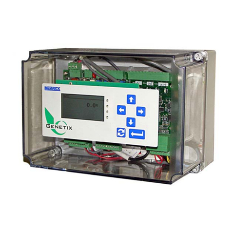
MERRICK Genetix GCM User manual

Genetix GCM Configuration and Troubleshooting for DF-1
Merrick Industries, June 2011
Genetix GCM Configuration and Troubleshooting for DF-1
Both serial ports in a Genetix GCM can be configured to support Allen-Bradley DF-1 point to
point protocol. This allows for establishing direct communications to Allen-Bradley PLCs, using
•Ch0, usually the built-in serial port,
•DeviceNet using the 1761-NET-DNI interfaces,
•EtherNet/IP using 1761-NET-ENI interfaces, or
•Data Highway Plus using KF2 or similar interfaces.
We currently support all methods described above.
The host can take control over and/or monitor the GCM, using CIT data table exchange. For
details of the CIT structure, see http://www.merrick-inc.com/mct/CIT.PDF
System Requirements
All versions of the Merrick Genetix GCM controller support Allen-Bradley (A-B) DF-1 Serial
Communications protocol and exposes a standardized Common Interface Table (CIT),
compatible with the A-B “Common Interface File” (CIF) specification. PCCC functions 1 (PLC2
Unprotected Read, 485CIF Read), 8 (PLC2 Unprotected Write, 485CIF Write) and 6 (PLC-2
Diagnostic Status) are supported.
The physical interface is normally 3-wire RS232, but 4-wire RS-422 can also be used. The host
or interface is assumed to maintain a cyclic conversation with the GCM, which exposes a
Common Interface Table (CIT), making it possible to monitor and/or supervise the GCM
completely.
Different data types are used for control/status bits, integer numbers and floating-point numbers.
Control/Status bits and Integer numbers are organized in 16 bit words. Parameters are organized
as IEEE 32 bit floating point numbers, located in two consecutive 16 bit words. For PLC's that
don't support floating point numbers, it is possible to split parameters into two 16 bit integers, one
containing the integer part and one containing the fractional part multiplied by 10,000 (four
implied decimal places).
Configuring the GCM
Configuring the GCM includes setting up communications parameters, register tags, warnings,
faults and external inputs and outputs. The register tags are set to make any internal GCM
parameter appear in Tag 1 R to Tag 5 R values. Standard feeder parameters are always
available. Warnings and faults are user preference qualified, associated with any logical I/O point
in the GCM. This configuration is done regardless if communications is used or not. Any logical
inputs you want to control from the PLC must be mapped to a network input. In the same way,
logical outputs must be mapped to network outputs for monitoring purposes.
It is recommended that you use the built in Terminal Monitoring and Configuration Interface
(TMCI) for setting up, troubleshooting and monitoring the DF-1 interface.The following menu
references and screen shots were taken using the GCM 101.1.6.8 Belt Feeder Controller
application. Operation and Maintenance Manuals as well as register specifications are available
at the Merrick Web Site:
http://www.merrick-inc.com/mct/GENApps/GENApps.htmTo enable network control parameters,
set Advanced Setup, Configuration, Network IO to Y.
http://www.merrick-inc.com/mct/GCMDF1.pdf Page 1 2011-06-14/Lars

Setting the GCM communications parameters
Set up the serial port in TMCI page X (Type PX<Enter>). Select which of the two serial ports (port
1 or 2) you will use. Port 1 is normally used for a user interface. Rotate between ports using
X<Enter>.
PX, TMCI Port Settings Screen
Parameter Comment
A : NewProt Protocol Selector. 4 for DF-1.
LastProt Last and currently used protocol. Unchanged until you restart the port.
B: BdIdx Index of the baud rate used:
0 300
1 1200
2 2400
3 4800
4 9600
5 19200
6 38400
7 57600
8 115200
9 230400
Set to the highest baudrate supported by the DF-1 host. Use 6, 38400 baud for
ENIs and DNIs.
C: LnPar UART Line parameter settings, hexadecimal. Bit encoded:
Bit 0, 1 Word Length – 00: 5 bits, 01: 6 bits, 10: 7 bits, 11: 8 bits.
Bit 2 Stop bits. 0: 1 stop bit, 1: 2 stop bits
Bit 3 Parity Enable
Bit 4, 5 Parity Select – 00: Odd, 01: Even, 10: Forced 1, 11: Forced 0
Bit 6 Enable Break transmission. Always 0!
Bit 7 DLAB Access. Always 0!
Typical setting is 0x03 for N, 8, 1 (most commonly used)
BLT>
PX X: Port 2 (UART1) settings
A: NewProt 4|LastProt 4|B: BdIdx 5|C: LnPar 0x03|
DF-1 | DF-1 | 19200 | |
En:WProt 0x0BFF|WOrder 0x0000|IntFra 0x0000|
Fn:Tag 1 0|Tag 2 0|Tag 3 0|Tag 4 0|Tag 5 0
Protocol |1: Unit Addr|2: Map Size|3: Max Time|4: LRC
Gn:All Modbus | 1| 1| 10.00|
Hn:DF-1 | 0| 1| 10.00| 0
In:CITMaster | 49| | 2.00|
Jn:UISServer | 1| | 20.00|
Kn:Scalenet | 49| 1| 10.00|
Scalenet Spec| Start Char| End Char| No Powup Hnd|
|L: 0x0A|M: 0x0D|N: 1|
Mon Period ms|O: 500| | |
R: Restart port
http://www.merrick-inc.com/mct/GCMDF1.pdf Page 2 2011-06-14/Lars

Parameter Comment
E1:WProt Write Protection bits, hexadecimal. Normally 0xBFF, meaning all tags except the
Primary Setpoint are write protected. See CIT documentation.
E2:Worder Floating Point Word Order bits, Hexadecimal. Set to 0x0000 for ControlLogix,
meaning all tags have normal word order. Set to 0x0FFF for PLC-5 and SLC. For
other PLCs, This has to be found by trial and error. See CIT documentation.
E3:IntFra Integer/Fraction bits, hexadecimal. Normally 0x0000, meaning all tags are
transferred as Floating Point numbers. Some MicroLogix PLCs don’t support
floating points. Use 0x0FFF in these cases. See CIT documentation.
Fn:Tag n,
n=1..5
Tagged register number. Up to five internal GCM Register Number you want to
monitor or set. The corresponding register value will appear in the "Tag 1 Rd V"
position in the CIT.
H1: Unit
Addr
DF-1 is a point-to-point protocol. Set to 0. Contrary to the official Allen-Bradley
documentation, Unit Addr must be zero for point-to-point operation. A non-zero
value will cause the telegram to be ignored unless the Destination field in the DF1
telegram matches Unit Addr.
H2: Map
Size
There are two different CIT layouts. This document covers CIT type 1 only.
Always set to 1!
H3: Max
Time
Max allowed time between incoming, valid DF-1 telegrams. If this time is
exhausted, the logical output Port 1 Timeout or Port 2 Timeout goes on,
depending on which port is used for DF-1 communications.
If you extend the size of the write table beyond word 59, you will overwrite “Write Protect”, “Word
Order”, “Int/Frac FP” and "Tag Reg 1-5" parameters from the PLC. This allows for multiplexing of
the parameters in the "Tag n Rd V" positions.
Configuring warnings and faults
Warnings and Faults are qualifiers to logical inputs and outputs, normally set by the user. See
“Digital I/O mapping” in the Operations and Maintenance manual. Warnings are considered to
require attention. Faults are considered to be fatal for the feeder operation, and the controller will
attempt to stop the feeder. In this example the warnings and faults are set up according to the
following table:
I/O point Qualifier Comment
LoadCell 1 Ovl Fault Invalid Load Cell Signal
LoadCell 1 Undl Fault Invalid Load Cell Signal
Blt Drive Fail Fault Time delayed indication that the belt drive has failed or is not
ready.
High Belt Load Warning Too much material on the belt
Parameter Fail Warning GCM Parameter load failure at GCM boot
Port 2 Timeout Warning Serial port 2 has not received a valid DF-1 telegram within set
time limit.
High Setpoint Warning Setpoint above upper limit. To detect floating point transfer
problems.
Manual State Warning GCM in manual (maintenance) mode. PID not active.
The warning and faults are normally set up using the user interface; Advanced Setup, Digital
I/O, Warings/Faults.
Warning bits (CIT word 18) and Fault bits (CIT word 19) go on whenever the corresponding
logical inputs or outputs go on and stay on until they are deliberately cleared. Faults and
http://www.merrick-inc.com/mct/GCMDF1.pdf Page 3 2011-06-14/Lars

Warnings can be cleared using the user interface or TMCI page K. Warnings can also be cleared
using CIT word 44, bit 8. See CIT documentation. TCMI page K looks like this
Note that the bit order in the CIT words for Warnings and Faults are not configurable. It is derived
from the order of logical outputs and logical inputs in the Digital Outputs and Digital Inputs
screens. If you add or remove a warning or fault qualifier to a logical output or input, the bit order
changes.
Configuring External Inputs and Outputs
Logical inputs and outputs can be mapped in three ways:
1. To a physical input or output. In this example the logical input Belt Drive Overload is
mapped to GCM Input 3, which, in turn, is connected to the Overload output of the belt motor
VFD. The logical input Run Permission is mapped to GCM Input 1. This input has to be ON
for the feeder to run in local or remote mode. The physical output GCM Output 1 is mapped
to the logical output Belt Forward. The output is then connected to the Start input of the belt
motor VFD.
2. To an external input or output. In this example, the Netw. Run Perm logical input is mapped
to External Input 1. This allows the PLC to control (start and stop) the feeder through the
External Inputs word 45, bit 0.
3. Unused Logical Inputs are typically connected to the Physical Inputs 'Always On' or 'Always
Off'.
The PLC controls physical inputs to the GCM in word 45 in the CIT. They appear in the GCM as
Netw Input 1.. Netw Input 16. You then map them to Logical Inputs in the GCM. Note that the
Network Inputs are numbered 1 - 16. Bits in the corresponding PLC word are typically numbered
0 - 15.
It is possible to have a physical input wrapped around to an external output (for monitoring
purposes) by first map the input to an 'Available I/O' point, and then map the same 'Available I/O'
point to an external output.
In this example, we want any logical I/O point that can cause a Warning or Fault visible in the
Network Outputs register (CIT Word 17), along with the logical outputs Ready, Running and
Good Feedrate. We only control one input, Netw. Run Perm.
This is how the inputs and outputs have to be mapped in the GCM for this example:
Logical Physical W/F CIT Word:Bit
Run Permission GCM Input 1 41:8
Belt Drv Fail GCM Input 3 41:10
Netw Run Perm. Netw Input 1 45:0
Belt Forward GCM Output 1 42:8
PRI>
PK Belt_1_6_8 Faults and Warnings
Warnings: 0x00000000, W to clear. Faults 0x00000000, F to clear
012 0 0 0 High Belt Load |006 0 0 0 LoadCell 1 Ovl
026 0 0 0 Parameter Fail |007 0 0 0 LoadCell 1 Undl
029 0 0 0 Port 2 Timeout |048 0 0 0 Belt Drive Fail
036 0 0 0 High Setpoint |
045 0 0 0 Manual State |
http://www.merrick-inc.com/mct/GCMDF1.pdf Page 4 2011-06-14/Lars

Logical Physical W/F CIT Word:Bit
Ready Netw Output 1 17:0
Running Netw Output 2 17:1
LoadCell 1 Ovl Netw Output 3 F 17:2
LoadCell 1 Undl Netw Output 4 F 17:3
Blt Drive Fail Netw Output 6 F 17:4
High Belt Load Netw Output 7 W 17:5
Parameter Fail Netw Output 8 W 17:6
Port 2 Timeout Netw Output 9 W 17:7
High Setpoint Netw Output 10 W 17:8
Manual State Netw Output 11 W 17:9
Setting Up the Setpoint Source
The GCM Setpoint Source must be set to Network (Serial): Advanced Setup, Feeder Control,
Source. The setpoint is taken from CIT word 46 and 47.
Connect the Host or Interface to the GCM and Check Communications
DF-1 normally uses the RS-232 interface if the GCM, because it is a point-to-point connection.
The cable must be short, less than 50 feet at 19200 baud. The GCM receives data on terminal 2
(RxD) with respect to GND, and transmits on terminal 3 (TxD) with respect to GND. GND is
terminal 4.
The RS232 interface allows for up to 50V common mode swing with respect to the 24V DC
negative terminal on the GCM.
Both ports have LED indicators for receive (Green) and transmit (Red) data. Port 2 are to the left
on the GCM board.
You can also use the RS-422 interface, especially if long cables are required. Use a cable
designed for RS-422. There should be two pairs, individually shielded, with a characteristic
impedance of around 150Ω. Belden 9368 or equivalent is a good alternative. Connect the shields
at the DF-1 and at the GCM. Add 121Ωterminating resistors at both ends of the RS485 line.
Connect one between Rx+ and Rx- and one between terminals Tx+ and TX- at each end of the
cable for a total of four resistors. The pin numbering on the GCM is left to right as you look at the
serial connector. See the picture on the next page. The GCM receives data on terminals 6 and 7
(Rx+ and Rx-), and transmits, after being correctly addressed, on terminals 8 and 9 (Tx+ and Tx-
).
Pair Part GCM Terminal RS-422 Name
5 Shield
1 1 6 Rx+
1 2 7 Rx-
2 1 8 Tx+
2 2 9 Tx-
The RS485 interface also allows for up to 50V common mode swing with respect to the 24V DC
negative terminal on the GCM.
http://www.merrick-inc.com/mct/GCMDF1.pdf Page 5 2011-06-14/Lars

This is an RS232 connection. The shield is
connected to terminal 1, GCM Chassis
Ground. For some hosts, it may be better to
connect the shield to pin 4, RS232 GND.
This picture shows a GCM connected to an
end point of a 4-wire RS422 line. Note the
terminating resistors.
http://www.merrick-inc.com/mct/GCMDF1.pdf Page 6 2011-06-14/Lars

Troubleshooting tips
Setting up industrial networks can sometimes be a daunting task. In this example, you may have
to deal with several mapping layers and communication protocols. Fortunately, there are
excellent troubleshooting tools available.
Look at the LED's on the GCM board.
The transmit (GCM sending) LEDs are red, and the receive LEDs are green. No receive activity
indicates cable or host problems. No transmit activity indicates addressing or serial parameter
problems
Check Data in the TCMI CIT Diagnostic Screen.
The TCMI CIT Diagnostic Screen (P1) displays data in the CIT as it is received and transmitted
over the Modbus port.
BLT>
P1 X: Port 2 (UART1) DF-1 Small Map CIT
16 in[0] Status/DNI 0080 44 in[0] Ctl/DNI 0083 [A]
17 in[1] Ext Outs 0003 45 in[1] Ext Ins 0001 [B]
18 in[2] Warnings 0000 46 fl[1] Feed SP 0.000005e+01 [C]
19 in[3] Faults 0000 48 fl[2] Sec SP 0.000000e+00
20 fl[2] Tag 1 Rd V 0.000000e+00 50 fl[3] Tag 1 Wr V 0.000000e+00
22 fl[3] Tag 2 Rd V 0.000000e+00 52 fl[4] Tag 2 Wr V 0.000000e+00
24 fl[4] Tag 3 Rd V 0.000000e+00 54 fl[5] Tag 3 Wr V 0.000000e+00
26 fl[5] Tag 4 Rd V 0.000000e+00 56 fl[6] Tag 4 Wr V 0.000000e+00
28 fl[6] Tag 5 Rd V 0.000000e+00 58 fl[7] Tag 5 Wr V 0.000000e+00
30 fl[7] Feedrate 5.000011e+01 60 in[16] WProt Bits 0BFF [J]
32 fl[8] Load 9.027183e+00 61 in[17] W Ord Bits 0000 [K]
34 fl[9] Speed 5.538830e+00 62 in[18] I/F Bits 0000 [L]
36 fl[10] Subtotal 5.171570e+05 63 in[19] Tag 1 Reg 0 [M]
38 fl[11] Total 5.171570e+05 64 in[20] Tag 2 Reg 0 [O]
40 in[24] App/Ver 0165 65 in[21] Tag 3 Reg 0 [Q]
41 in[25] PhIn 5102 66 in[22] Tag 4 Reg 0 [T]
42 in[26] Ph Out L/H 0902/0000 67 in[23] Tag 5 Reg 0 [U]
X to change port
addr: 44|size: 8|CSErrs: 0|Timee: 0
rxfme: 0|rxlfm: 0|rtgms: 3496|ttgms: 1748
http://www.merrick-inc.com/mct/GCMDF1.pdf Page 7 2011-06-14/Lars

Note that the values are only updated on valid DF-1 telegrams. If no telegrams have been
received, most values are zero. As you can see, the layout follows the CIT exactly. All integer
values are presented in hexadecimal format except the Tag register numbers. The ‘e’ format for
the floating points can help troubleshooting FP transfers. You are reading from the left column,
and writing to the right. If you succeed with the integrity bit, you should see bit 7 in the Sts/DNI
and Ctl/DNI toggle.
Check Data in the Communication Diagnostic Screen.
The TCMI Communications Diagnostic Screen (P2) displays communication related data and
counters.
In this shot, out of 4900 successful exchanges, there was none lost to errors. The last command
received was 8 (PLC2 Unprotected Write), starting at word 44, 4 bytes long.
NewProt Protocol used. 4 for DF-1. See “Setting the GCM communications parameters” on
page 2.
LastProt Transient indication of the last protocol initialized. Normally same as “Prot”
BaudIdx Index of the baud rate used: See “Setting the GCM communications parameters” on
page 2.
LinePar Line parameters. See “Setting the GCM communications parameters” on page 2.
ISRProt Protocol Selector for the UART interrupt service routine. Typically same as Prot
Route Routing for the XDC board. Always 0 for DF-1.
PrState Prelude State. Not used, always zero.
Port Port array index. 0 for port 1 (UART 0, lower row on connector) 1 for port 2 (UART
1, upper row on connector)
Ints UART Interrupt counter. Increments for any serial activity. Since the UARTs have
16 byte FIFOs, this counter typically increments slower than Rxchs and Txchs.
Rxchs Received characters counter
Txchs Transmitted characters counter
Rxuae Receiver UART error counter.
BLT>
P2 X: Port 2 (UART1) DF-1 Diagnostics
NewProt 4|LastProt 4|BaudIdx 5|LinePar 0x03
ISRProt 4|Route 0|PrState 0|Port 1
Ints 14234|Rxchs 33744|Txchs 15601|
Rxuae 18|Rxlua 0x84|sta 0x61|cha 0x06
Rxillmsr 0|Rxilluae 0|Txboverr 0|Rxboverr 0
Iir 0xC1|Rxtmo 48673|wastmo 1|IllInts 0
unita 0| |Map 1|MaxTime 10.00
rxsta 0|txsta 4|State 2|isTimeout 0
addr 44|size 4|cmd 8|subf 0
cCRC 0xC8BF|tCRC 0xC8BF|bcnt 0|lalen 14
rtgms 4900|htgms 4900|ttgms 4900|NotMe 0
rxcse 0|rxfme 1|rxlfm 19|timee 1
LenEnd 0|TimEnd 0|WaiEnd 4901|E: enddl 0
Rx: 10 02 03 FE 08 00 E8 2A 58 00 03 00 00 00 00 00 00 00 10 03 BF C8 71 00 00
Tx: 10 06 10 02 FE 03 48 00 E8 2A 10 03 20 A7 04 00 00 00 00 00 00 00 00 00 00
Z Zero Counters
http://www.merrick-inc.com/mct/GCMDF1.pdf Page 8 2011-06-14/Lars

Rxlua UART Line Status Register at the last UART error. Bit encoded:
Bit 0 Receiver data ready. This is not an error
Bit 1 Overrun error
Bit 2 Parity error
Bit 3 Framing error
Bit 4 Break condition
Bit 5 Transmitter holding register empty. This is not an error
Bit 6 Transmitter empty. This is not an error
Bit 7 At least one error in receiver FIFO
Sta UART Line status register at the last character received. See Rxlua above. Typically
0x61.
Cha Hex representation of the last character received
Rxillmsr Counter for illegal Modem Status Interrupt. The UART is configured to not generate
MSRs. Only UART1 has modem status lines.
Rxilluae Counter for illegal (not enabled) UART error interrupts. Should always be 0.
Txboverr Transmitter buffer overrun counter. Increments if an attempt is made to transmit
characters past the end of the transmitter character buffer, indicating a bug in the
protocol handler. Should always be 0.
Rxboverr Receiver buffer overrun counter. Increments when the receiver buffer is filled up
without an end of telegram condition.
Iir UART Interrupt Identification Register at last interrupt.
Wastmo Indicates that the last UART receiver interrupt was a UART character timeout (Stale
data in FIFO) rather than a “FIFO trigger limit reached”.
Illints Counter for undocumented IIR patterns. There appears to be a bug in the UART
that, under adverse conditions, causes this to happen.
Unita Controller/Station/Node number ID of the GCM in multidrop settings. Should be 0
for DF-1
Map Enumeration of the CIT map format. Set to 1 for standard CIT mapping.
MaxTime Silence time for isTimeout (see below) in seconds. A value of zero is interpreted as
“never” meaning isTimeout will never be true.
Rxsta Character receiver state enumeration:
0 Waiting for first UART interrupt
1 Not used in DF-1
2 Buffering data
3 Waiting for first CRC character
4 Waiting for second CRC character
5 Received telegram complete
6 Not used in DF-1
7 NAK received
8 ENQ received
Txsta Character transmitter state enumeration:
0 Idle
1 First character in UART, RS485 transmitter enabled
2 Ongoing transmission from ISR
3 Last byte of telegram placed in UART FIFO
4 Waiting for UART transmitter empty to disable the RS485 transmitter
http://www.merrick-inc.com/mct/GCMDF1.pdf Page 9 2011-06-14/Lars

State Communication task state enumeration:
0 Not used
1 Initializing (transient)
2 Waiting for some characters received
3 Waiting for end-of-telegram condition
4 Handling message
5 – 8 Not used in DF-1
isTimeout No valid telegrams have been received for MaxTime (see above), and MaxTime is
greater than zero.
addr Starting Word in last CIT read or write telegram. Typically 16 or 44.
size Number of Bytes in last CIT read or write telegram
cmd Telegram command enumeration. Protocol dependent. For DF-1:
0 for PLC-2 Unprotected Read, 8 for PLC-2 Unprotected Write, 6 for browsing
subf ModBus telegram 8 subfunction. Not used in DF-1
cCRC Calculated CRC in incoming telegram.
tCRC CRC field in incoming telegram. Must be equal to cCRC for valid checksum.
bcnt Byte count field in incoming and outgoing ModBus telegrams. Not used in DF-1
lalen Number of characters in the last completed incoming telegram
rtgms Counter for incoming telegrams. This includes all telegrams with a valid end
condition
htgms Counter for handled telegrams. This includes all telegrams addressed to this GCM,
correctly formatted, with a correct checksum.
ttgms Counter for transmitted telegrams
NotMe Counter for received ,correctly formatted telegrams not addressed to this GCM
rxcse Counter for received telegrams with checksum errors
rxfme Counter for received, incorrectly formatted telegrams. See rxlfm below
rxlfm Last encountered received format error enumeration. Protocol dependant. Note 1.
timee Counter for isTimeout. Increments every time isTimeout goes from False to True
LenEnd Counter for telegrams who have had the end condition determined by the content of
the length determining fields within the telegram. All DF-1 telegrams belongs to this
category.
TimEnd Counter for ModBus RTU telegrams who have had the end condition determined by
UART character timeout. Not used in DF-1
WaiEnd Counter for ModBus RTU and UISServer telegrams who have had the end condition
determined by absence of incoming characters for enddl (see below) ATRX ticks.
Not used in DF-1
enddl Min wait in ARTX ticks (currently 5 ms) for absence of incoming characters to
determine end condition. Not used in DF-1
Note 1. Rxlfm indicates what kind of format error occurred last, as rxfme increments. In some
cases, a NAK response is sent back to the master/client. This is indicated in the
following table with a numerical value. An “x” indicates that the telegram will be ignored
for the format error. An empty field indicates that the specific format error does not
apply for this protocol.
Rxlf
m DF1 Format error
http://www.merrick-inc.com/mct/GCMDF1.pdf Page 10 2011-06-14/Lars

Rxlf
m DF1 Format error
1-10 Not used in DF-1
11 x ISR Receiver buffer overrun
12 x ISR Transmitter buffer overrun
13 x ISR Characters received after end of message, before reply sent
14 Not used in DF-1
15 0x50 Outside CIT legal read space on CIT read or write
16-17 Not used in DF-1
18 0x50 Write to read-only space in CIT
19 x STX, ENQ, ACK or NAK expected – DF-1 Sequence error
20 x NAK received on NAK or ACK
21-34 Not used in DF-1
34 x Transmitter length rollover – Should never happen
Use the integrity bit.
In the PLC, toggle the integrity bits (Word 44, bit 7) every 2 seconds. Monitor the integrity echo bit
(Word 16 bit 7). If they stop toggling, communications has failed, and appropriate steps can be
taken. The integrity bit can be monitored in the TCMI CIT Diagnostic Screen (P1), and the GCM
can be set up to monitor the activity of the integrity bit, potentially generating a Warning or Fault if
the bit stops toggling.
http://www.merrick-inc.com/mct/GCMDF1.pdf Page 11 2011-06-14/Lars
Other MERRICK Controllers manuals
Popular Controllers manuals by other brands
Woodward
Woodward PG-EG Installation and operation manual
Eaton
Eaton PowerXL DE1 series quick start guide
Compit
Compit SOLARCOMP 911 Installation and operating instructions

Samson
Samson 42-36 Mounting and operating instructions
ABB
ABB ControlMaster CM10 Commissioning instructions
Larson Electronics
Larson Electronics Golight 2020 instruction manual

High End Systems
High End Systems High End LCD Controller for Studio Color user manual
Philips
Philips dynalite DDBC120-DALI installation manual
Omni Instruments
Omni Instruments TCW120B user manual

GeoVision
GeoVision GV-AS1520 user manual
Panduit
Panduit FPC-600-A operating instructions
Ingersoll-Rand
Ingersoll-Rand EC34ES-1 manual
