Instructions
INSTRUCTIONS 270353
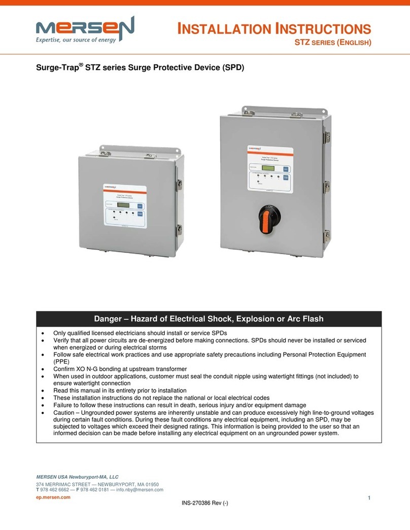
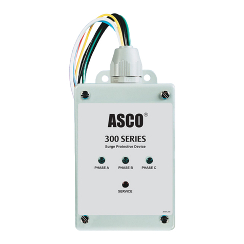
Surge-Trap®Type 1 SPD for NEMA Type 4X Applications
DANGER
Hazard of Electric Shock, Burn or Explosion
• Thisequipmentmustbeinstalledandservicedonlyby
qualiedelectricalpersonnelinaccordancewithnational
andlocalelectricalcodes.
• Turnoffallpowersupplyingthisequipmentbefore
workingonequipment.
• Alwaysuseaproperlyratedvoltage-sensingdeviceto
conrmpowerisoff.
• Replacealldevices,doorsandcoversbeforerestoring
powertothisequipment.
• Donotapplypetroleum-basedproductsto
non-metallicparts.
Improperinstallationormisapplicationofthesedevices
mayresultinseriousinjurytotheinstallerand/ordamage
toelectricalsystemorrelatedequipment.Protectiveeye
wearandclothingshouldbewornwheneverworking
aroundhazardousvoltages.
Failuretofollowtheseinstructionscouldresultinserious
injuryordeath.
CAUTION
• DonotattempttoopenortampertheSurge-Trap
deviceinanywayasthismaycompromiseperformance
andwillvoidthewarranty.
• Meggerandhi-potentialtestsmaydamagethedevice.
• Disconnectallpowersupplyingtheequipmentand
isolatetheSurge-Trapdevicebeforetesting.
• Priortoinstallation,conrmthattheSurge-Trapisrated
forthecorrectvoltage,currentandfrequencyequivalent
totheapplication.
• ForuseinNEMAType1through4XApplications.
PANEL MOUNT AND WIRING
1. Turnoffallpowersupplyingthisequipment.
2. PanelMount:Punchouta¾″enclosureknockoutfrom
thepanelorthemountinglocationascloseaspossible
tothewherethewireswillterminate.Whereothertypes
ofmountingarerequired,pleaseconsultthefactory.
3. Inserta¾″closenippletotheMyersHubprovidedand
attachedtotheSurge-Trap®SPD.InsertSPDwires
carefullythroughtheknockouthole.Tightena¾″steel
conduitlocknuttosecuretheSPDtotheenclosure(as
showninFigure1).
4. Connectthewiresasshownintheappropriatewiring
diagram.
INSTALLATION Figure1PanelMount
374MerrimacStreet,Newburyport,MA01950
88HornerAvenue,Toronto,Ontario,CanadaM8Z5Y3
ep-us.mersen.com ep-ca.mersen.com
5. OvercurrentProtection:Type1SPDsareULListed
andtestedtobeself-protecting.Theydonotrequire
upstreamprotectionaccordingtoUL1449andSection
285oftheNEC.However,werecommendanupstream
disconnectorbreakerformaintenanceandsafety.
Manyswitchesandcircuitbreakershavelimitations
regardingmorethanonewireinaconnector.Breaker
manufacturerscanprovideinformationonthelimitations
oftheiravailableterminals.Whereadditionalwires
areprohibitedunderthesameterminal,manytimes
installinganewcircuitbreakerisconvenient.Typical
sizesare15,20and30amps.
6. Foroptimaldeviceperformance,useshortestwire
lengthofwireaspossible.Cutofftheexcesswire
insteadofcoilingitup.Avoidsharpbends.
7. Beforeenergizing,installershallverifyserviceand
separatelyderivedsystemNeutraltoGroundbonding
jumperpertheNECrequirements.
¾"closenipple
¾"steelconduit
lockingnut


