merten ARGUS 180 User manual

V5710-581-02 03/16
ARGUS 180 flush-mounted sensormodule© Schneider-Electric2014V5710-581-0203/16
System M
Argus 180 flush-mounted sensor module
Art. no. MEG5710-03../04..
Argus 180 flush-mounted sensor module
Art. no. MEG5710-60..
System Design
ARGUS 180 flush-mounted sensor module with
switch
Art. no. MEG5711-03../04..
ARGUS 180 flush-mounted sensor module with
switch
Art. no. MEG5711-60..
–Tobecompletedwith:
• corresponding inserts (see function overview)
• Frame in corresponding design.
¼DANGER
Risk of serious damage to property and per-
sonal injury, e.g. from fire or electric shock,
due to incorrect electrical installation.
Safe electrical installation can only be ensured if
the person in question can prove basic knowl-
edge in the following areas:
• Connecting to installation networks
• Connecting several electrical devices
• Laying electric cables
These skills and experience are normally only
possessed by skilled professionals who are
trained in the field of electrical installation technol-
ogy. If these minimum requirements are not met
or are disregarded in any way, you will be solely li-
able for any damage to property or personal inju-
ry.
ARGUS 180 flush-mounted sensor
module
Operating instructions
Necessary accessories
For your safety
en
The ARGUS 180 flush-mounted sensor module (re-
ferred to below as sensor module) is a movement de-
tector for installation indoors. The sensor module detects
moving heat sources (e.g. people) within an adjustable
area of detection and triggers a staircase lighting func-
tion.
The maximum range of the sensor module is approx. 8
m to the left/right and approx. 12 m to the front at a 180°
angle of detection. As long as movement is detected, the
connected load remains switched on. The adjustable
overshoot time only begins when no further movements
are detected (trigger function).
The sensor module is equipped with a light sensor with
an adjustable brightness threshold so that the lighting is
only switched on when surroundings are below a speci-
fied brightness threshold (movement detector function).
If there is sufficient natural light, the switchable presence
function allows the sensor module to switch off the light-
ing even when a person is present.
|The specified range and brightness threshold re-
fer to average conditions at the recommended
mounting height of approx. 1.10 m and should
therefore be taken as guide values. The range
can vary greatly when the temperature fluctuates.
For sensor modules with a switch, the function switch
can be used to switch between "Automatic mode", per-
manently "ON" and permanently "OFF".
Function overview of the sensor module
on receiving inserts
Complete the sensor module with the receiving inserts
for switching or dimming in order to perform local light
control and other functions.
Getting to know the sensor module
Switching/dimming
• Electronic switch insert Sensor module:
brightness-dependent
staircase lighting function
• Relay switch insert
• Universal dimmer insert
• 1-10 V insert
• Dali insert
• Electronic switch insert Sensor module with a
switch:
brightness-dependent
staircase lighting function,
permanently switching on/
off
• Relay switch insert
• Universal dimmer insert
• 1-10 V insert
•DALIinsert
• Electronic switch insert,
2-gang
Sensor module:
Channel 1: brightness-de-
pendent staircase lighting
function,
channel 2: brightness-in-
dependent staircase light-
ing function
• Relay switch insert, 2-
gang
• Universal dimmer insert,
2-gang
• Electronic switch insert,
2-gang
Sensor module with a
switch:
Channel 1: brightness-de-
pendent staircase lighting
function, permanently
switching on/off
Channel 2: brightness-in-
dependent staircase light-
ing function, permanently
switching on/off
• Relay switch insert, 2-
gang
• Universal dimmer insert,
2-gang
Function overview of the sensor module
on sending insert
Complete the sensor module with the sending central
unit insert in order to perform global light control via the
PlusLink (PL) .
|Movement/presence detectors are not suitable
for use as components of an alarm system.
|Movement/presence detectors can trigger false
alarms if the installation site is unsuitable.
Movement/presence detectors switch on as soon as
they detect a moving heat source. This can be a person,
but also animals or differences in temperature through
windows. In order to avoid false alarms, the chosen in-
stallation site should be such that undesired heat sourc-
es cannot be detected (see section „Selecting the
installation site“).
Front:
AFunction switch:
– : permanently "OFF"
– Auto: "Automatic mode"
– : permanently "ON"
BGreen LED (during permanent ON/OFF switching
via the function switch / 24-h staircase lighting cir-
cuit)
CRed LED (in test mode)
Rear:
AModule interface
BDIP switches
1: Presence function / movement detector function
2: Double overshoot time for channel 2
3: Prewarning for channel 1
4: 24-h staircase lighting circuit
CPotentiometer for overshoot time
DPotentiometer for brightness threshold
EPotentiometer for sensitivity
Global light control:
• Central unit insert Sensor module / sensor
module with switch:
brightness-independent
staircase lighting function
Using the sensor module with alarm
systems
Connections, displays and operating
elements
A
B C B C
1 2 3 4
ON DIP
Test
10s
2
min
30min
Time
Sensi-
tivity
A
BE
C D
Lux
V5710-581-02 03/16
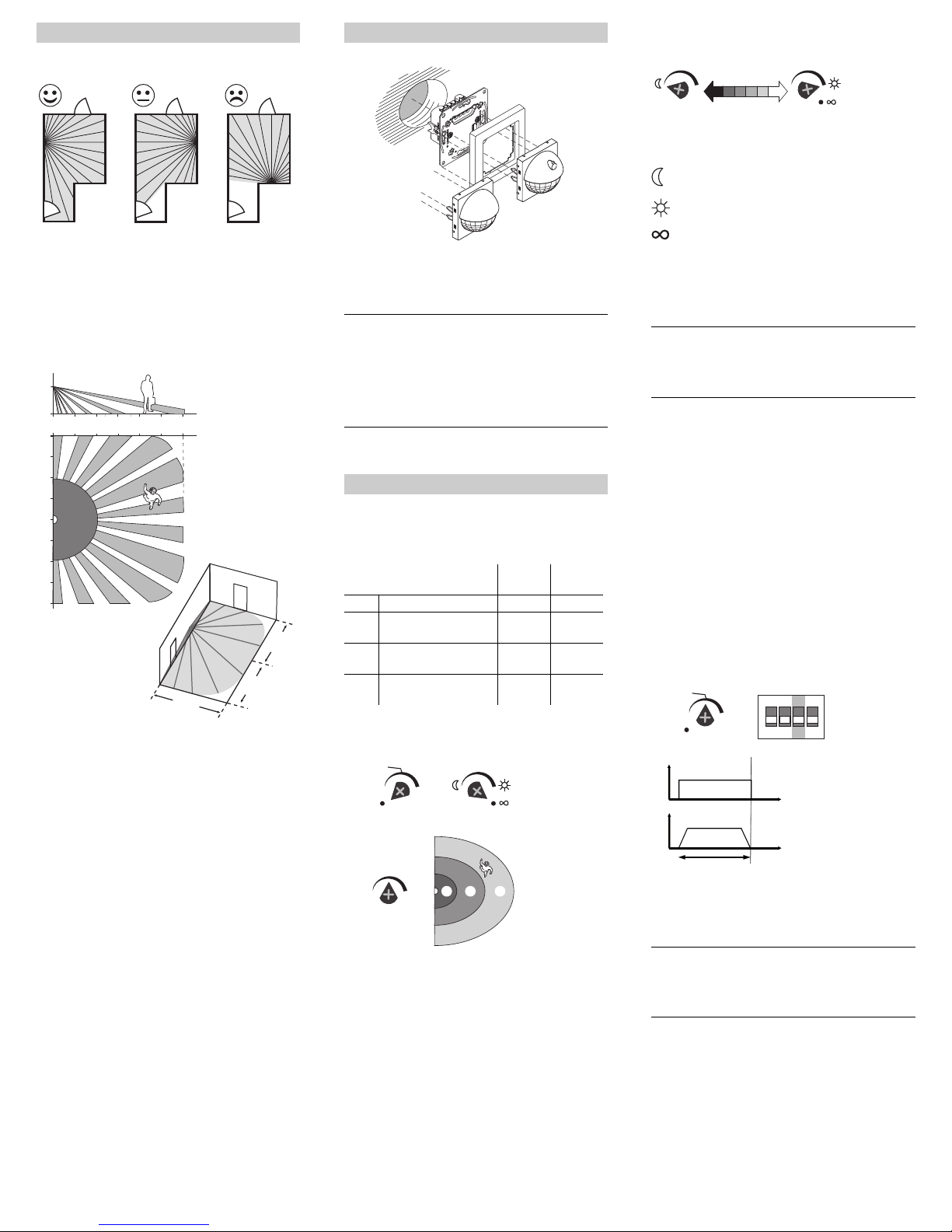
• Only mount the sensor module in positions that allow
the desired area to be monitored optimally.
• Install the sensor module on the wall at a height of ap-
prox. 1.10 m above the floor. Any mounting height
which deviates from this will affect the range.
• Install the sensor module laterally with respect to the
direction of movement so that the beam paths are in-
tersected as vertically as possible.
• Maximum area of detection of the sensor module:
180° angle of detection, approx. 12 m to the front, ap-
prox. 8 m to the left and right.
• In order to ensure continuous monitoring, e.g. of a
long hall, the areas of detection of the individual sen-
sor modules have to intersect.
• Movement/presence detectors detect objects that ra-
diate heat. You should select an installation site that
will not result in undesired heat sources being detect-
ed, such as:
– Switched-on lamps in the area of detection
– Open fires (such as in fireplaces)
– Moving curtains, etc., that cause a different temper-
ature in their surrounding environment due to strong
sunlight.
– Windows where the influence of alternating sunlight
and clouds could cause rapid changes in tempera-
ture.
– Larger heat sources (e.g. cars) that are detected
through windows.
– Rooms flooded with light where light is reflected on
objects (e.g. the floor) which can be the cause of
rapid changes in temperature.
– Windowpanes heated up by sunlight
– Dogs, cats, etc.
• To prevent faulty operation, the insert should be in-
stalled in a wind-resistant switch box. With switch box-
es and pipe cabling systems, a draught of air at the
back of the equipment can trigger the module.
• Avoid direct sunlight. This can destroy the sensor in
extreme cases.
Selecting the installation site
12 m
8 m 8 m
0
1,1
m
2 4 6 8 10 12
8
0
2
4
6
8
6
4
2
AInsert (see function overview)
BFrame
CSensor module with/without a switch
|When the mains voltage is activated, the sensor
module switches channel 1 on for 30 s and then
switches it off. Channel 2 remains switched off.
During the following 2 s the sensor module does
not react to any movement. After this initialisation
period has elapsed, the sensor module is ready
for operation.
On the rear side of the sensor module, the potentiometer
can be used to set the module's sensitivity, brightness
threshold and overshoot time.
Additional possible settings using DIP switches:
Setting the sensitivity
1Activate the test mode and set the brightness
threshold to "infinite".
The red LED lights up when movement is detected.
2Infinitely set the sensitivity.
3Walk around the area of detection and check wheth-
er the sensor module is switching as desired. Adjust
the sensitivity if required.
Mounting the sensor module
Setting the sensor module
Pos. ON
(upper)
Pos. OFF
(lower)
DIP 1 Presence function Active Inactive
DIP 2 Double overshoot time
for channel 2
Active Inactive
DIP 3 Pre-warning for channel
1
Active Inactive
DIP 4 24-h staircase lighting
circuit via PlusLink
24 h "ON" 24 h "ON"
or "OFF"
B
C
A
C
Test
10s
2 min
30min
Sensi-
tivity
A B C
A
B
C
1
2
Setting the brightness threshold
4Infinitely set the desired brightness threshold. The
sensor module switches below the set brightness
threshold.
5Check that the module switches at the desired/set
brightness. Adjust the brightness threshold if re-
quired.
|In combination with a 2-gang insert, the bright-
ness threshold only applies to channel 1. Chan-
nel 2 always switches independently of
brightness.
Setting the staircase lighting function
You can set the type of staircase lighting function (with-
out/with pre-warning) and the overshoot time.
When setting the overshoot time, you specify how long
the connected load remains switched on (continuously
from 10 s to 30 min.)
The pre-warning indicates the end of the overshoot time.
The loads are switched off briefly and then back on again
(in combination with switch inserts), or are dimmed down
slowly (in combination with dimmable inserts). The loads
are switched off after the pre-warning time has elapsed
(30 s, not adjustable).
1Select the type of staircase lighting function and set
the overshoot time
Staircase lighting function without pre-warning
ASwitching without pre-warning
BDimming without pre-warning
COvershoot time
|In the case of a 2-gang insert, the overshoot time
for both channels is set using the potentiometer.
In order to double the overshoot time for channel
2, slide DIP switch 2 to "ON".
Detects movement in the dark (approx. 10 lux)
Detects movement during daylight (approx.
1000 lux)
Detects movement independently of brightness
4
1
1 2 3 4
ON DIP
Tes t
10s
2 min
30min
B
A
C
t
t

V5710-581-02 03/16
Staircase lighting function with pre-warning
ASwitching with pre-warning
BDimming with pre-warning
COvershoot time
DPre-warning time (30 s, not adjustable)
|In the case of a 2-gang insert, the overshoot time
for both channels is set using the potentiometer.
In order to double the overshoot time for channel
2, slide DIP switch 2 to "ON".
The pre-warning only applies to channel 1.
Activating/deactivating the presence
function
In the case of brightness-dependent movement detec-
tion, the sensor module constantly monitors the bright-
ness in the room and compares it to the set brightness
threshold. If sufficient natural light is available, the sen-
sor module will switch the lighting off even if a person is
present.
The sensor module's presence function is deactivated
as a factory default. You can activate the function ("ON")
and deactivate it ("OFF") using DIP switch 1.
When the presence function has been deactivated, the
sensor module continues to carry out the movement de-
tector function.
Setting the 24-h staircase lighting cir-
cuit
The DIP switch 4 can be used to set a 24-hour staircase
lighting circuit which you can retrieve from another loca-
tion via PlusLink.
The following options are available for this:
•DIP4"ON":only switch on the staircase lighting for
24 h via PL
• DIP 4 "OFF": switch the staircase lighting on/off for
24 h via PL
1
1 2 3 4
ON DIP
Test
10s
2 min
30min
B
D
A
C
t
t
1 2 3 4
ON DIP
1 2 3 4
ON DIP
If sources of interference (such as light sources) inad-
vertently switch on the connected luminaires, you can
block these areas out. Adjust the sensor module's area
of detection by applying, moving or shortening the mask-
ing segments supplied:
1Place the masking segments on the centre of the
lens and latch it into place at the top between the
hood and the lens.
2If necessary: shorten the masking segments at the
positions marked so only the close range of the lens
is used.
3Move the masking segments precisely onto the
area that you wish to block from detection.
|The use of masking segments affects the sensor
module's brightness threshold. Readjust the
brightness threshold.
(Only for ARGUS 180 flush-mounted sensor module with
switch)
You can set three functions using the function switch A
on the sensor module.
• Position Auto: The sensor module is in automatic
mode and switches the loads on when movement is
detected and then off again after the overshoot time
has expired (movement detector function).
• Position (permanently "ON"): load is switched on
permanently (no movement detection). Green LED
lights up.
• Position (permanently "OFF"): load is switched off
permanently (no movement detection). Green LED
lights up.
|Notes:
• The function switch has the highest priority.
All PlusLink commands are ignored at switch
positions and .
• In combination with a 2-gang insert the function
switch controls both channels together.
Blocking out areas
Operating the sensor module with
switch
123
A
Controlling loads from another location
via PlusLink with:
• Push-button module on central unit insert
• Sensor module on central unit insert
• Side controller Plus, 1-gang/2-gang
• Mechanical push-button
Example of global control with push-button module
on central unit insert
Starting the staircase lighting function
When the push-button module on the central unit insert
Ais actuated, all local sensor modules Bin the PL
lines start the set staircase lighting function inde-
pendently of brightness.
APush-button module on central unit insert (alterna-
tively:side controller Plus for one PL line)
BSensor module in PL line
24-h staircase lighting circuit
• Upper left push-button: switch on the staircase lighting
for 24 h. Green LED lights up.
• Lower left push-button: switch off the staircase lighting
for 24 h (prerequisite: DIP 4 on "OFF"). Green LED
lights up.
|If DIP 4 is switched to "ON", the lighting cannot be
switched off for 24 h.
• Upper/lower right push-button: deactivate the 24-h
staircase lighting circuit.
APush-button module on central unit insert (alterna-
tively: side controller Plus for one PL line)
BSensor module in PL line
Controlling the sensor module from
another location
A
B
PL1
PL4
PL3
PL2
A
B
PL1
PL4
PL3
PL2
24 h

V5710-581-02 03/16
Example of global control with mechanical push-
button
When the mechanical push-button Ais actuated, all lo-
cal sensor modules Bin the PL lines start the set stair-
case lighting function independently of brightness.
AMechanical push-button
BSensor module in PL line
Example of global control with panic button on the
central unit insert
When the panic button Bis actuated, all local sensor
modules Cin the PL lines start a fixed overshoot time
lasting 30 minutes (panic scene) independently of
brightness. For sensor modules with a switch, the func-
tion switch must be set to "Auto" for this.
|When a push-button module is used on the cen-
tral unit insert, the function can be stopped early.
Press the right push-button in order to do this.
When the central unit insert is used in combina-
tion with a sensor module, the panic function is
not available.
APush-button module on central unit insert
BMechanical push-button (panic button)
CSensor module in PL line
|The global control via PlusLink is possible with
the combination of a central unit insert and sensor
module.
Operating the sensor module: global
staircase lighting function via PlusLink
A
B
<
0,5 s
PL
AB
C
PL2
PL4 PL3
PL1
30 min
Example of global control via module on
the central unit insert
If the sensor module Aon the central unit insert detects
a movement, it sends a trigger command to all local sen-
sor modules Bin the PL lines.
The local sensor modules Bcheck the ambient bright-
ness. The staircase lighting function only starts if the
brightness is below the set brightness threshold.
You can also start the staircase lighting function of the
push-button modules Comfort and Comfort Plus in the
PL lines.
ASensor module on central unit insert (alternatively:
side controller Plus for one PL line)
BSensor module in PL line 1
CPush-button modules Comfort or Comfort Plus with
set staircase lighting function
|Notes:
• Push-button modules Cwithout a set stair-
case lighting function ignore the commands via
PlusLink.
• On the central unit insert, the sensor module al-
ways sends independently of brightness.
• The sensor module function switch does not
function on the central unit insert.
• The sensor module's DIP switches do not func-
tion on the central unit insert.
Example of two sensor modules oncentral unit in-
serts in the PL line
ASensor module on central unit insert (alternatively:
side controller Plus for one PL line)
BSensor modules in PL line
A
B
C
PL1
PL4
PL3
PL2
A
B
A
PL1
PL1
Load is not switching on.
• The sensitivity is set too low.
– Reset the sensitivity.
• The brightness threshold is set too low.
– Reset the brightness threshold.
• For sensor modules with a switch, the function switch
is set to .
– Set the function switch to "Auto".
Load is permanently switched on.
• The overshoot time is set too high. The sensor module
constantly detects new movements and restarts the
overshoot time.
– Reduce the overshoot time or sensitivity.
• For sensor modules with a switch, the function switch
is set to .
– Set the function switch to "Auto".
The module is not reacting. The red LED is flashing
quickly.
• The sensor module and insert are not compatible (e.g.
blind control insert)
– Plug the sensor module onto a compatible insert
(see function overview).
Gothaer Straße 29, 40880 Ratingen
www.merten.com
www.merten-austria.at
Customer care centre:
What should I do if there is a problem?
Technical data
Angle of detection: 180°
Number of levels: 6
Number of zones: 46
Number of presence
detectors: 2
Recommended
mounting height: 1.10 m
Range (adjustable
under „Sensitivity“): max. approx. 8 m to the right/left,
approx. 12 m to the front
Brightness threshold:
approx. 10 lux to approx.
1000 lux (infinitely adjustable),
brightness independent
Overshoot time: approx. 10 s to approx. 30 min
(infinitely adjustable),
test mode (1 s)
Display elements: 1 red LED
1 green LED
Operating elements
Function switch
(only for modules
with a switch): , Auto,
DIP switches: 1: Presence function / movement
detector function
2: Double overshoot time for
channel 2
3: Prewarning for channel 1
4: 24-h staircase lighting circuit
Connection: module interface with 8 contact
pins
Dispose of the device separately from
household waste at an official collection
point. Professional recycling protects people
and the environment against potential nega-
tive effects.
Schneider Electric GmbH c/o Merten
Phone: +49 2102 - 404 6000
Table of contents
Other merten Accessories manuals

Popular Accessories manuals by other brands


Keystone
Keystone WT09 quick start guide

VOLTCRAFT
VOLTCRAFT PB-17 operating instructions

Honeywell
Honeywell Fire-Lite Alarms SD365TA Installation and maintenance instructions

PreCise Biometrics
PreCise Biometrics Precise 100 A user guide

Curv
Curv DBL01 quick start guide

Logitek
Logitek ULTRA-VU Operation & service manual