merten MEG5252-03.. User manual

V5252-581-01 10/16
Rotary moduleArt.-Nr. MEG5252-03../-04..© Schneider-Electric 2014V5252-581-0110/16
–Tobecompletedwith:
• corresponding inserts (see function overview)
• Frame in corresponding design
¼DANGER
Risk of serious damage to property and per-
sonal injury, e.g. from fire or electric shock,
due to incorrect electrical installation.
Safe electrical installation can only be ensured if
the person in question can prove basic knowl-
edge in the following areas:
• Connecting to installation networks
• Connecting several electrical devices
• Laying electric cables
These skills and experience are normally only
possessed by skilled professionals who are
trained in the field of electrical installation technol-
ogy. If these minimum requirements are not met
or are disregarded in any way, you will be solely li-
able for any damage to property or personal inju-
ry.
Rotary module
Operating instructions
Art. no. MEG5252-03../-04..
Necessary accessories
For your safety
en
With the rotary module (referred to below as module),
you can carry out various functions such as:
• Switching, dimming and controlling blinds
• Calling up, changing and saving Basic light and blind
scenes
Function overview of the modules on re-
ceiving inserts
Complete the module with the receiving inserts for
switching, dimming or controlling blinds/roller shutters in
order to carry out local light and blind control.
Function overview of the modules on
sending inserts
Complete the module with the sending central unit insert
in order to carry out global light and blind control via the
PlusLink (PL).
Front:
ARotary knob
BLED segments (status, orientation)
CModule push-buttons
Rear:
AModule interface
Getting to know the rotary module
Switching:
• Electronic switch insert Local switching, calling up
and saving local light
scenes
• Relay switch insert
• Electronic switch insert,
2-gang
Separate switching of both
channels locally
• Relay switch insert,
2-gang
Dimming:
• Universal dimmer insert Local switching and dim-
ming, calling up and saving
local light scenes
• 1-10 V control insert
•DALIinsert
• Universal dimmer insert,
2-gang
Separate dimming of both
channels locally
Controlling blinds/roller shutters:
• Blind control insert Local raising/lowering, call-
ing up and saving local Ba-
sic blind scenes
Global light and blind control:
• Central unit insert global switching, global
dimming, global raising/
lowering, calling up and
saving global Basic light/
blind scenes
Connections, displays and operating
elements
B
AC
A
AInsert (see function overview)
BFrame
CModule
|An initialisation period of approx. 15 s begins
when mains voltage is switched on or the module
is plugged in. The LED segments flash during this
initialisation period. After this period has elapsed,
the module is ready for operation.
"Blind/roller shutter" will be referred to below as just
"blind".
Switching loads on/off
In combination with 1-gang insert
• With push-buttons
• With rotary knob
– by rotating or briefly pressing the knob
|With dimmer inserts a quick half turn is required to
switch directly to full brightness.
Mounting the module
Operating the module: local light and
blind control
B
C
A
<
0,5 s

V5252-581-01 10/16
In combination with 2-gang insert
• With push-buttons
– right push-button: channel 1
– left push-button: channel 2
• With rotary knob
– switch both channels together by rotating or briefly
pressing the knob.
|If a channel is already switched on, then pressing
the rotary knob will switch this channel off. If both
channels are in the same state, then pressing the
rotary knob will switch both channels together.
Dimming loads
In combination with 1-gang insert
• With push-buttons
• With rotary knob
– by rotating the knob
<
0,5 s
<
0,5 s
> 0,5 s
In combination with 2-gang insert
• With push-buttons
– right push-button: channel 1
– left push-button: channel 2
•Withrotaryknob
– dim both channels together.
– simultaneously to max. / min. brightness.
|If the channels have different brightness values
then the difference between these remains con-
stant when dimming to max. / min. brightness.
When one channel reaches the max. / min.
brightness, the difference is reduced until the
common max. / min. brightness is reached.
Controlling blinds
• With push-buttons
– raising/lowering (> 0.5 s)
– up/down in steps (< 0.5 s)
•Withrotaryknob
– raising/lowering (fast half turn of the knob)
– up/down in steps (slow rotation of the knob)
>
0,5 s>
>
0,5 s
< 0,5 s
>> 0,5 s
< 0,5 s
> 0,5 s
Retrieving local light or blind scenes
(Only in combination with 1-gang inserts)
Standard scenes
All devices are delivered from the factory with preset-
tings for a light or blind scene.
1Retrieve scene: press the left upper push-button or
the left lower push-button briefly.
• The devices of the light scene adopt the saved bright-
ness value.
• The devices of the blind scene initially move to the up-
per position. After a running time of 2 minutes, they
move to the saved position.
Changing and saving local light scenes
(Only in combination with 1-gang inserts)
1Set the brightness value.
2Save scene: press and hold the left upper push-
button or the left lower push-button.
All lamps are switched off briefly and then back on again
to indicate that the saving procedure was successful.
Then the lamps adopt the saved brightness value.
Changing and saving local Basic blind
scenes
For Basic blind scenes, you can only save the fixed posi-
tion values of "fully up/down".
1Move the blind to the upper position and wait for the
running time of 2 minutes until the LED segments go
out.
2Set the desired position of the blind:
– Position "up": no further settings required
– Position "down": lower the blind
3Save scene: press and hold the left upper push-
button or the left lower push-button.
The blinds are lowered and raised by one step to indicate
that the saving procedure was successful.
Left upper push-but-
ton:
Light on (100%) / blind up
Left lower push-but-
ton:
Light off / blind down
< 0,5 s
>
3 s
12
>
3 s
1
3
2

V5252-581-01 10/16
Controlling connected loads from an-
other location via PlusLink with
• Central unit insert or side controller Plus, 1-gang/2-
gang:
switching, dimming, controlling blinds and retrieving
scenes
• Mechanical push-button/double push-button
|The global control via PlusLink is possible with
the combination of a central unit insert and a rota-
ry module.
Global light control
Example of globally switching on/off and dimming
the 1-4 PL lines
Pressing the right push-button of the rotary module on
the central unit insert controls all loads in the PL lines to-
gether:
• Short press on the push-button (< 0.5 s): switching on/
off
• Long press on the push-button (> 0.5 s): dimming
|Rotating the knob has no effect on the loads in the
PL lines.
Pressing the knob switches off all loads in the PL
lines and lowers the blinds by one step.
AModule on central unit insert
BInserts for switching and dimming (see function
overview)
Controlling the module from another
location
Operating the module: global light and
blind control via PlusLink
A
B
B
PL4 PL3 PL2 PL1
<
0,5 s
<
0,5 s
>
>
0,5 s
>
>
0,5 s
Global blind control
Example of global raising/lowering and up/down in
steps of the 1-4 PL lines
Pressing the right push-button of the rotary module on
the central unit insert controls all loads in the PL lines to-
gether:
• Long press on the push-button (> 0.5 s): raising/lower-
ing
• Short press on the push-button (< 0.5 s): up/down in
steps
|Rotating the knob has no effect on the loads in the
PL lines.
Pressing the knob switches off all loads in the PL
lines and lowers the blinds by one step.
AModule on central unit insert
BBlind control insert
|Global scenes via PlusLink are possible with the
combination of central unit insert and rotary mod-
ule.
|When you save a scene, this affects all connect-
ed devices of the PL lines.
Proceed as follows to change and save a scene accord-
ing to your requirements:
1Change the states of individual devices in the light
and/or blind scene.
2Save the scene.
Retrieving global light or blind scenes
Standard scenes
All devices are delivered from the factory with preset-
tings for a light or blind scene.
1Retrieve scene: press the left upper push-button or
the left lower push-button briefly.
• The devices of the light scene adopt the saved bright-
ness value.
• The devices of the blind scene initially move to the up-
permost position. After the set running time has
elapsed (the standard is 2 minutes), the blinds move
to the saved position.
Operating the module: retrieving,
changing and saving global scenes via
PlusLink
Left upper push-button: Light on (100%) / blind up
Left lower push-button: Light off / blind down
Panic button: Light on (100%) / blind down
A
B
B
PL4 PL3 PL2 PL1
< 0,5 s
>> 0,5 s
< 0,5 s
> 0,5 s
Changing and saving light scenes
Using a dimmer as example:
1Set the brightness values of the lamps that you want
to change on the receiving device.
2Save scene: press and hold the left upper push-
button or the left lower push-button.
All lamps are switched off briefly and then back on again
to indicate that the saving procedure was successful.
Then the lamps adopt the saved brightness value.
Changing and saving blind scenes
In combination with the rotary module or push-button
module Basic on the receiving insert, you can only save
the fixed position values of "fully up/down" (1A) for
blind scenes.
In combination with the push-button modules Comfort,
Comfort Plus and Wiser on the receiving insert, you can
save any position values (1B).
The blinds are lowered and raised by one step to indicate
that the saving procedure was successful.
1ASet the positions (fully up/down) of the blinds
that you want to change on the receiving device.
BSet the positions (any values) of the blinds that
you want to change on the receiving device.
2Save scene: press and hold the left upper push-but-
ton or the left lower push-button.
>
>
3 s
12
>
>
3 s
A
A
B
12

V5252-581-01 10/16
Status display
In combination with 1-gang insert
In combination with 2-gang insert
In combination with a blind control insert
Operating the module: basic functions
Operation Status feedback
Switching All LED segments
light up when the
load is switched on
Dimming The LED segments
light up corre-
sponding to the
brightness of the
load
Operation Status feedback
Switching
•TheLEDseg-
ments to the right
of Ashow the
status of
channel 1
•TheLEDseg-
ments to the left
of Ashow the
status of
channel 2
Dimming
•TheLEDseg-
ments to the right
of Ashow the
dimming status
of channel 1
•TheLEDseg-
ments to the left
of Ashow the
dimming status
of channel 2
Operation Status feedback
Raising/lowering
•ArotatingLED
indicator shows
the direction of
movement of the
blind. Upwards in
a clockwise di-
rection.
• Display during
the running time
(max. 2 min)
Up/down in steps •ArotatingLED
indicator moves
according to the
blind direction.
Upwards in a
clockwise direc-
tion.
• Display: half turn
A
A
=
=
=
=
Setting the brightness of the status dis-
play
Switching orientation lighting on/off
All LED segments light up at min. brightness.
Standard: switched off
Switching memory function on/off
(Only in combination with dimmer inserts)
The device memorises the brightness level that was last
set.
Standard: switched off
1Switching on memory function
2Switching off memory function
Resetting to default settings
Operation Status feedback
Upper LED segments
flash 4 times
Operation Status feedback
Right LED segments
flash 4 times
Operation Status feedback
All LED segments
flash 8 times
13
2
==
10 s < 0,5 s
10x
10x =
=
1
2
6x
6x
=
=
10 s
Changing operating mode
(Only available for modules with software from version
0B in combination with universal dimmer insert, 1-gang,
art. no. MEG5171-0000 from version 0B)
The insert automatically recognises the connected
loads. In some cases, the connected LED lamps may not
work correctly with the automatic load detection. In this
case you can switch the operating mode to RL LED (from
trailing edge phase to leading edge phase).
|In the operating mode "leading edge phase for
LED lamps" (RL LED mode), LED lamps can only
be connected up to a lower dimmer load. (See
operating instructions "Universal dimmer insert".)
Standard: automatic load detection
1Setting the RL LED mode
2Resetting to automatic load detection
Gothaer Straße 29, 40880 Ratingen
www.merten.com
www.merten-austria.at
Customer care centre:
Operation Status feedback
Lower LED segments
flash 4 times
Technical data
Display elements: 8 LED segments
Operating elements: • 4 push-buttons
• Rotary knob/push-button
Connection: module interface with 8 con-
tact pins
Dispose of the device separately from house-
hold waste at an official collection point. Pro-
fessional recycling protects people and the
environment against potential negative ef-
fects.
Schneider Electric GmbH c/o Merten
Phone: +49 2102 - 404 6000
1
2
14x
14x
=
=
This manual suits for next models
1
Other merten Control Unit manuals
Popular Control Unit manuals by other brands
National Instruments
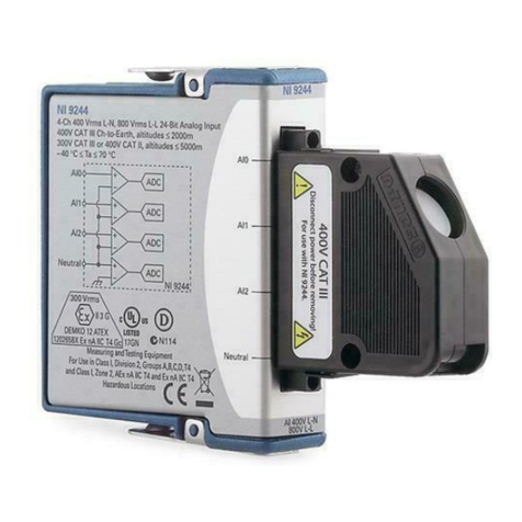
National Instruments NI-9244 User manual and specifications
Murata
Murata ABR Getting started guide

GEM
GEM 534 Installation, Operating and Maintenance Instruction

IBASE Technology
IBASE Technology ET870 Series user manual
Norbec
Norbec IM4 operating instructions

BETAFPV
BETAFPV Micro TX user manual


