│OPERATING INSTRUCTIONS MODULE IM4
97, rue de Vaudreuil Boucherville (Quebec) J4B 1K7 Canada T : 1 877 667-2321 | NORBEC.COM
Date of release : August 2023
4
2.5 Panic Alarm
This alarm can be triggered when the backlit push
button is pressed and held, located inside, near
the door opening. When pressing this button, the
lights will turn ON and an audible alarm from the
keypad will occur and the dry contact (normally
closed) from the alarm relay will activate the
external alarm signal (low voltage). The display
will also show the message HELP. Once this alarm
is triggered, the mute button will not work. The
push button must be pressed and held for 3
seconds to deactivate the alarm.
2.6 Muting an Alarm
Pressing the ''Silent'' button on the keyboard
during an alarm will mute the audible signal but
the associated alarm message will remain until the
alarm condition disappears.
2.7 Battery Backup
The 9-Volt battery holder is located inside the
controller. In normalcondition, this battery should
maintain the temperature display and the alarm
messages in operation during power outages. The
dry contact (normally closed) from the alarm relay
will activate the external alarm signal (low
voltage).
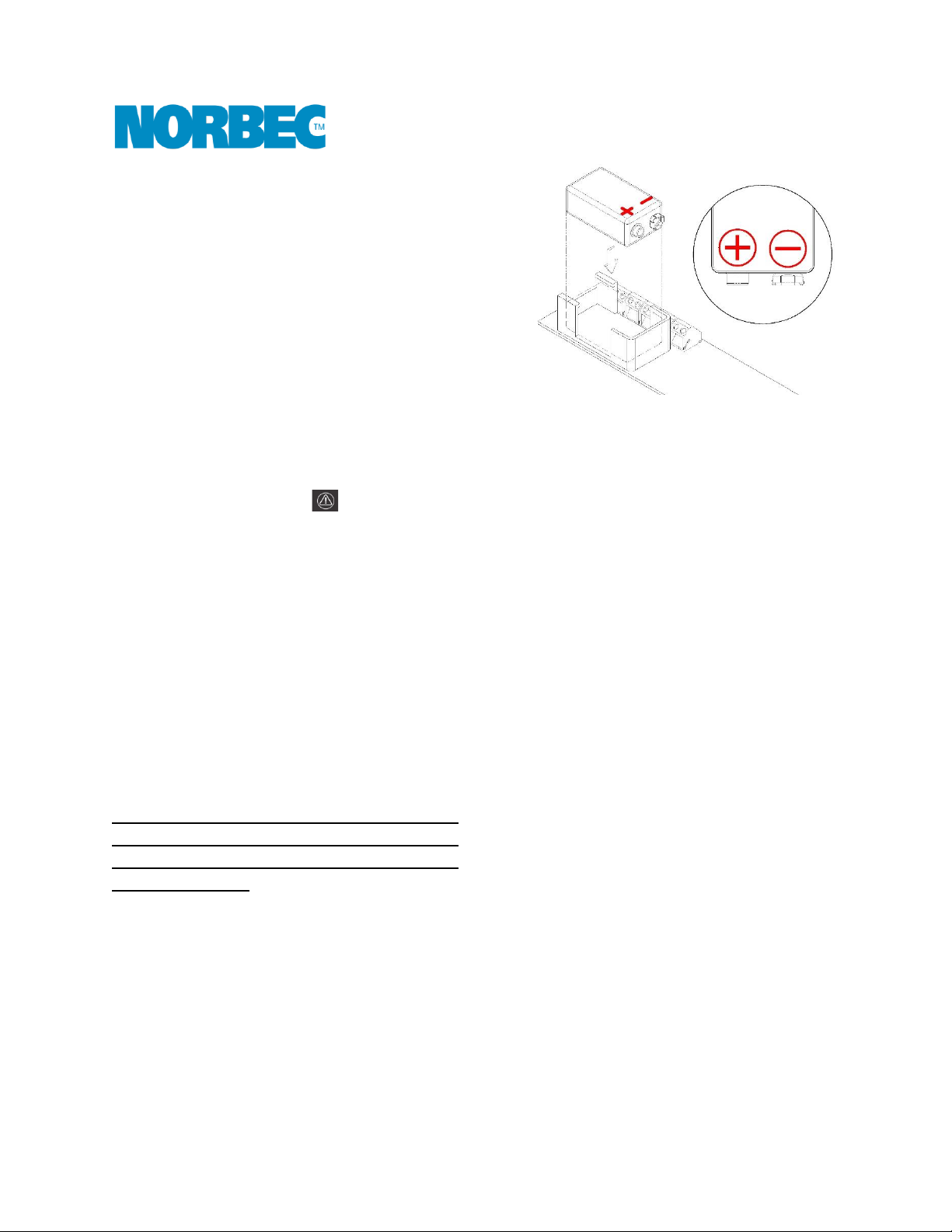
The rechargeable battery is positioned upside
down in the base. It is necessary to reposition it
as shown in the diagram below during the first
on-site installation.
1. Switch off the module power supply.
2. Unscrew the screws holding the keyboard.
3. Lift the keyboard to access the back of the
module.
4. Install the battery.
2.8 Three-Way Switch for Lighting
This option allows controlling lighting through two
different doors in automatic mode. You must refer
to the IM4 wiring diagrams for the proper
electrical connection.
3Options
3.1 Fan Failure Alarm
When a ventilation system circulates air in
concealed spaces around the exterior of walk-in
cold rooms, optional sensors can be supplied to
monitor the presence of air flow on each blower.
With this option, if airflow stops, the system
triggers an audible alarm from the keyboard, the
dry contact (normally closed) from the alarm relay
will activate the external alarm signal (low
voltage) and the display will show the message
EXT ALARM alternating with the actual
temperature.
3.2 Dry contact
The dry contact links the IM4 module to an
external alarm system trough a wire. A signal is
sent to the external alarm when an alarm from the
IM4 module is activated.