MERYTRONIC ARIADNA ILF-12 User manual

ARIADNA ILF-12
PHASE AND FEEDER
IDENTIFIER
USER GUIDE V 3.0

2
INDEX
1. SYSTEM DESCRIPTION........................................................................................................6
1.1. COMMUNICATION BETWEEN CD AND LD IN AUTOMATIC MODE ..........................7
2. EQUIPMENT CONTENTS......................................................................................................8
3. DEVICE DESCRIPTION.........................................................................................................9
3.1. CENTRAL DEVICE CD ..................................................................................................9
3.2. LINE DEVICE LD..........................................................................................................10
4. CENTRAL DEVICE (CD) EQUIPMENT CONNECTION ......................................................11
4.1. STAR TRANSFORMER: 3 PHASE + NEUTRAL LV OUTPUT....................................11
4.1.1. LD DEVICE CONNECTION POINT PHASE-NEUTRAL: .......................................12
4.1.1.1. STEP ONE: CONNECT SENSOR RINGS TO FEEDERS................................12
4.1.1.2. STEP TWO: CD SUPPLY CABLE CONNECTION...........................................13
4.1.1.3. STEP THREE: SELECT WORKING MODE, AUTO-FN OR MAN-FN MODES15
4.1.3. LD DEVICE CONNECTION POINT PHASE-PHASE:............................................20
4.2. DELTA TRANSFORMER: 3 PHASE LV OUTPUT (NO NEUTRAL)............................21
4.2.1. LD DEVICE CONNECTION POINT PHASE-PHASE:............................................22
4.2.1.1. STEP ONE: CONNECT SENSOR RINGS TO FEEDERS................................22
4.2.1.2. STEP TWO: CD SUPPLY CABLE CONNECTION...........................................23

3
4.2.1.3. STEP THREE: SELECT WORKING MODE, AUTO-FF OR MAN-FF MODES...25
5. LINE DEVICE (LD) CONNECTION ......................................................................................30
5.1. PHASE TO NEUTRAL NETWORK POINTS (STAR, B1 WITH NEUTRAL OR B2):......30
5.2. PHASE TO PHASE NETWORK POINTS (DELTA OR STAR B1 WITH NO NEUTRAL
AVAILABLE):..........................................................................................................................31
6. IDENTIFICATION PROCESS...............................................................................................32
6.1. AUTO MODE...................................................................................................................32
6.2. MAN MODE.....................................................................................................................37
7. TIPS......................................................................................................................................39
8. TECHNICAL FEATURES .....................................................................................................41
9. QUALITY STANDARDS AND SECURITY ...........................................................................43
10. WARRANTY AND TECHNICAL SERVICE ........................................................................44

4
Safety information, read these indications first:
Used symbols:
Earth terminal
Caution, check the user guide explanation
European conformity
Supply cable connection to mains is OK
Error on supply cable connection to mains
CAT III measurement category: makes reference to the distribution level and
permanent circuits inside a building
Ariadna Network Identifiers meet European Low Voltage Directive 72/23/CEE and are
compliant with:
- Central Device: EN 50178 (Electronic equipment for use in power installation)
- Line Device: EN 61010-1 CATIII
Read the complete user guide before using the equipment and its accessories.

5
Avoid working alone
Do not use the equipment in gas or explosive vapor areas.
Before using the equipment check cables and coils to see if there is any
mechanical damage; if so replace them. Try to locate breaks or missing plastic
components. Pay special attention to the isolating material that surrounds
connectors.
Disconnect all sensors, cables and accessories that are not being used.
Use the earth connection to connect the equipment to ground and do not
apply voltage.
Do not apply voltages above the nominal working voltage of the equipment.
Before use, check the voltage level coincides with the supply voltage and frequency.
In case of security functions deterioration:
If the equipment is used in a way not specified by the manufacturer, its protections
could become affected.
Before use, check cables and rest of accessories to make sure they are not
damaged; replace them if necessary.
If the equipment or its accessories are damaged or do not work properly, do not use
them and send them for repair.

6
1. SYSTEM DESCRIPTION
The purpose of this equipment is to achieve the maximum possible information
regarding the low voltage network topology. This means knowing the
connectivity of each accessible point of the LV network.
In this document connectivity is defined as the existing connection relationship
between a network point that is being analyzed, and the MV/LV transformer
substation, feeder and phase that feeds it.
Ariadna ILF12 equipment consists of two devices: Central Device (CD) that is
installed in the MV/LV transformer substation that supplies electricity to the area
whose topology is being achieved, and the Line Device (LD) that is carried by
the operator along the network points whose connectivity is being analyzed. The
CD and the LD communicate with each other using the electric distribution
network.

7
1.1. Communication between CD and LD in Automatic Mode
1st
2nd
CD
LD
INFORMATION
CD injects phase and CD
number identification
signals through each
phase of the MV/LV
transformer.
If the network point where the LD is
connected to belongs to the same
MV/LV transformer, it will receive data
info, which will be shown on the LCD
display.
INFORMATION
After receiving
phase and CD
number, it will
transmit a signal
upstream towards
the transformer.
CD receives this signal
through the sensor ring that
corresponds to the feeder
where the LD has been
connected to.
This way MV/LV transformer, feeder and phase
connectivity information is clearly identified.
4th
3rd
INFORMATION
CD identifies the
corresponding feeder
and injects its
identification result code
towards LD.
Receives feeder
identification signal
injected by CD and
displays this
information.

8
2. EQUIPMENT CONTENTS
Ariadna ILF12 equipment consists of:
-CD: Central Device that can identify up to 3 phases and 12 feeders
-12 Sensor Rings (Rogowski Coils)
-5 core supply cable to connect the CD to the transformer LV busbar
-LD: Line Device (UL-220) with graphic display.
-LD soft case
-Two cables, red (phase) and blue (neutral) to connect the device to the
network points to be analyzed.
-Spare fuse box.
-4 AA 1.5V batteries.
-User guide.
-Equipment soft bag.

9
3. DEVICE DESCRIPTION
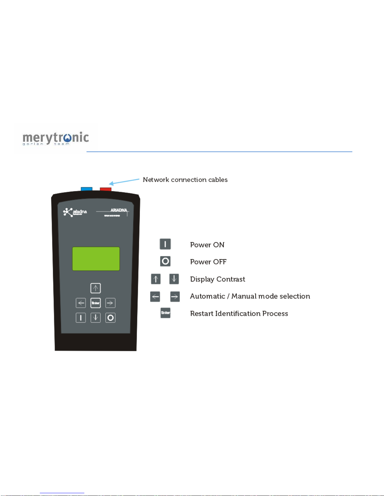
3.1.Central Device CD
Power ON
Power OFF
UC Number Selection
Automatic / Manual mode selection
UC restart
10
3.2. Line Device LD

11
4. CENTRAL DEVICE (CD) EQUIPMENT CONNECTION
Depending on the LV side of the transformer there can be different network
configurations.
4.1. STAR Transformer: 3 phase + neutral LV output
In this LV configuration the transformer will have a neutral cable. Depending on
the network voltage it can be*:
CD connection point
LD connection point
B1 transformers:
oV phase-phase:
230Vac
Vphase-phase:
230Vac
oV phase-neutral:
130Vac
Vphase-neutral:
130Vac
B2 transformers:
oV phase-phase:
400Vac
Vphase-phase:
NOT AVAILABLE
oV phase-neutral:
230Vac
Vphase-neutral:
230Vac
* See equipment working voltage ranges in 5. Technical Features
12
4.1.1.LD device connection point Phase-Neutral:
Whenever the network point where the LD device is going to be connected,
has an accessible neutral point, the working procedure to connect the CD at
the transformer side should be:
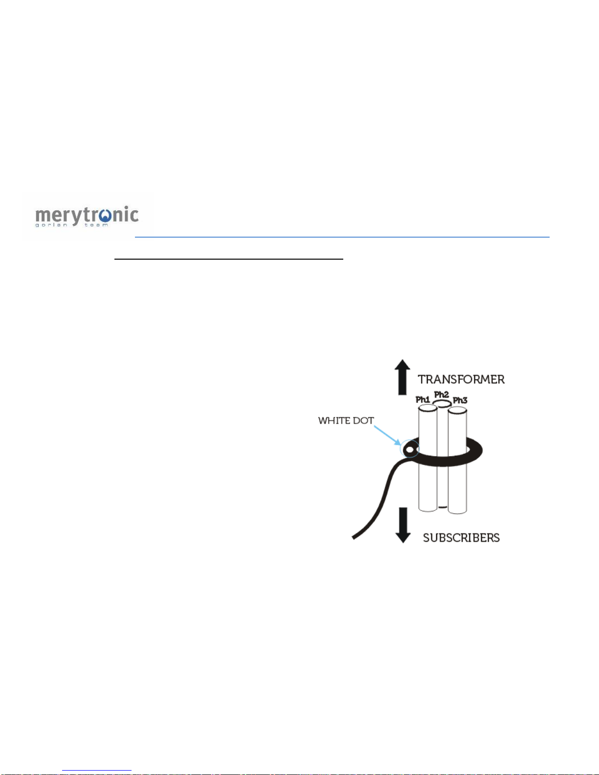
4.1.1.1. Step ONE: Connect sensor rings to feeders
Sensor rings must be connected
checking that each ring embraces all
three phases of a feeder, never the
neutral, and making sure sensor
ring’s polarity (white dot) faces the
transformer side.
The coil must be connected to one of
the BNC inputs of the front panel.

13
4.1.1.2. Step TWO: CD supply cable connection
Connect the supply cable to the CD’s front panel.
It is not possible to work with more than one
transformer at a time, so if there is more than one
transformer in the substation, work must be done with
each transformer separately.
Connect cables to MV/LV transformer’s output:
-F1, green conductor -> Phase
-F2, yellow conductor -> Phase
-F3, brown conductor -> Phase
-N, blue conductor -> Neutral
-GND, green-yellow -> Ground

14
The connection to the network should look like the following figure:

15
4.1.1.3. Step THREE: select working mode, AUTO-FN or MAN-FN modes *
In AUTO mode, the communication between the Central Device and the Line
Device is made automatic, and takes place as described in 1.1 (Communication
between CD and LD).
However, there are certain network points where, due to network topology,
feeder length (over 1km), noise produced by harmonics, etc., it is not possible
for signals from CD to reach the network point where LD device has been
connected to. The MAN mode has been developed for these cases.
When working in MAN mode, the LD works as a transmitter and the CD as a
receiver.
For further information check 6.1 (Identification process: Automatic mode) and
6.2 (Identification process: Manual mode).
*Note: Both UC and UL must be in the same mode:
- UC Automatic mode and UL Automatic mode.
- UC Manual mode and UL Manual mode.

16
AUTO -FN mode:
P
B
Action
Display
Observations
Turn ON the device
The device will start to
perform a mains
connection test
In case of connection
ERROR: check
corresponding supply
cable fuse and clamp
connection
If any phase or neutral
show an X symbol, it will
not identify connectivity
data
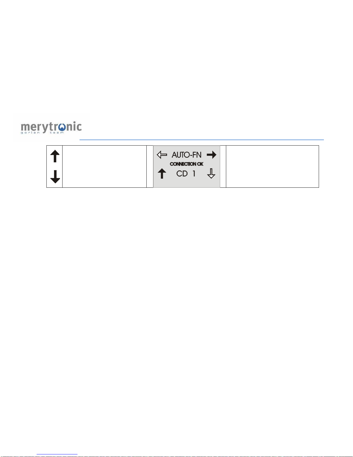
Connection OK, the device
is ready to identify
connectivity information
17
* Whenever there is more than one CD connected on nearby transformers, CD
selection number may be used to differentiate between them.
*Select Central Device
number
This number will be
received and displayed on
the LD

18
MAN -FN mode:
PB
Action
Display
Observations
Select MAN-FN
mode
The device will start to
perform a mains
connection test
In case of connection
ERROR: check
corresponding supply
cable fuse and clamp
connection
If any phase or neutral
show an X symbol, it will
not identify connectivity
data
Connection OK, the device
is ready to identify
connectivity information

19
Check CD front panel LEDs:
- If a sensor ring has been connected to the front panel connector its
corresponding LED must turn ON.
Otherwise check the sensor ring’s resistance with an ohm meter.
It should be within 30 to 50 ohm range.
- If no sensor ring has been connected to a front panel connector its
corresponding LED must be OFF.
If all LEDs are blinking check mains connection.
If they still blink, please check supply cable’s connections are good, and
also fuses if necessary.

20
4.1.2.LD device connection point Phase-Phase:
If the LD connection point has no neutral, and transformer’s LV side is B1 type
(Vphase-phase 230Vac, Vphase-neutral 130Vac) the working procedure
should be as in Transformer LV side in DELTA mode.
Refer to section 4.2 DELTA Transformer: 3 phase LV output (no neutral)
Table of contents
Popular Security Sensor manuals by other brands


hager
hager EE880 manual

ZyXEL Communications
ZyXEL Communications SHD1111 quick start guide

Guardian
Guardian 01320 instruction manual

PCS
PCS NLD100-CDR operating instructions

Electro Detectors
Electro Detectors Zerio Plus EDA-R6000 installation instructions

Sentek
Sentek HD 912 Series Installation Wiring Diagram


