MES SQA-V Gold User manual

and
SQA-V
S e r v i c e M a n u a l
V e r s i o n 2 . 4 8 / 2 . 4 9 / 2 . 6 0
Catalog #7501
Rev: April 2014

and SQA-V Service Manual 24_Apr_2014
2
Table of
Contents
SECTION I: Introduction
Automated Test Results 4
Technology 4
Automated System 4
Visualization System 5
SECTION II: System Specifications
Sperm Quality Analyzer –SQA-V Version 2.48/2.49 6
SECTION III: System Overview
Front Panel 9
Key Pad 9
Rear Panel 9
Side Panel 9
The Chassis Assembly 10
The Cover Assembly 10
Schematic of the SQA-V Motherboard 10
SECTION IV: System Components and Accessories
Measurement Capillary 10
Slide Adaptor 11
Cleaning, Accessory and V-Sperm Kit 11
SECTION V: Electronic Self- Test and Auto-Calibration
Start Up 11
Prior to testing a sample 12
SECTION VI: Getting Started / Set Up
Getting Started / Set Up 12
SECTION VII: Troubleshooting
Overview 13
SECTION VIII: Technical Support and Part Replacement Instructions
Opening the SQA-V 13
Closing the SQA-V 13
Printer 13
Keypad 14
Power Supply (PSU) 14
Power Supply Unit 15-16
Power Inlet 17
Fan Assembly 17
Operation Monitor (lower LCD Screen) 18
Focus Knob 19
Video Screen 20
LED Replacement 22
CCD Replacement and Cleaning 22-25
Video Display Monitor 26
Video Control Board Replacement 26
Surge Protector Replacement 26
Capillary Sensor Troubleshooting and Replacement 27
Optical Board to LED Cable Replacement 29
Visualization System Upgrade (VSU) 30
and SQA-V Service Manual 24_Apr_2014
3
SECTION IX: Error Messages
Stabilization Failed 32
Self-Test Failed 32
Electronic Noise 32
Concentration out of Range 33
Control Testing 33
Sample size out of range 34
I-Button warning screen 34
Communication Error 34
SECTION X: Appendix
Cleaning the SQA-V 35
I-Button Loading Instructions 36
Replacing the Processor 38
Power Supply Troubleshooting Flowchart 40
and SQA-V Service Manual 24_Apr_2014
4
SECTION I: Introduction
The SQA-V is a high performance analytical medical device that combines state-of-
the-art technology in electro-optics, computer algorithms and video microscopy. The
system performs a precise, 75-second semen analysis. The SQA-V runs a self-test and
auto-calibration on start-up and also runs external quality controls. The SQA-V
incorporates two systems: An automated system and a visualization system
which allows flexibility to analyze all types of semen samples.
Automated Test
Results
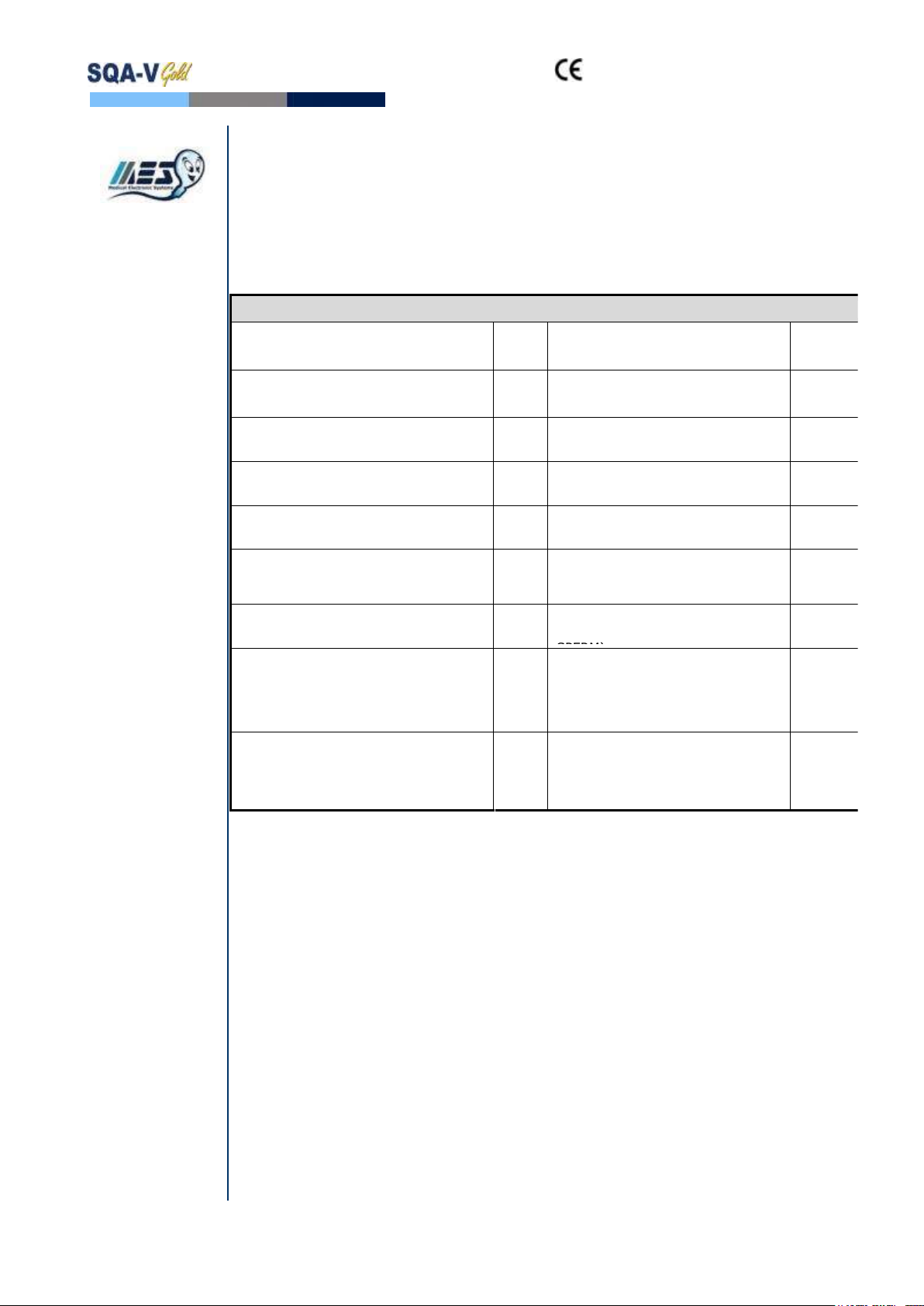
WHO 5th Semen Parameters with SQA-V Abbreviation in Brackets
Sperm Concentration
(SPERM CONC.)
M/ml
Velocity
(VELOCITY)
mic
/sec
Total Motility
(TOTAL MOTILITY <PR+NP>)
%
Sperm Motility Index
(SMI)
#
Progressive Motility
(PROG. MOTILITY <PR>)
%
Total Sperm Number / ejaculate
(SPERM #)
M
Non-progressive Motility
(NONPROG. MOTILITY <NP>)
%
Total Motile Sperm / ejaculate
(MOT. SPERM)
M
Immotility
(IMMOTILTIY <IM>)
%
Total Progressively Motile Sperm /
ejaculate (PROG. SPERM)
M
Sperm Morphology (normal forms, %)
(MORPH. NORM. FORMS, WHO 5th)
%
Total Functional Sperm / ejaculate
(FUNC. SPERM)
M
Motile Sperm Concentration
(MSC)
M/ml
Total Morphologically Normal
Sperm / ejaculate (MORPH. NORM.
SPERM)
M
Progressively Motile Sperm
Concentration (PMSC)
M/ml
Postvasectomy: Motile, Immotile
and Total Sperm/Scan
(#SPERM/SCAN: MOTILE,
IMMOTILE and TOTAL)
#
Functional Sperm Concentration:
Progressively Motile Sperm with Normal
Morphology (FSC)
M/ml
Postvasectomy: Motile, Immotile
and Total Sperm/sample volume
(#SPERM/SAMPLE VOLUME:
MOTILE, IMMOTILE AND TOTAL)
M
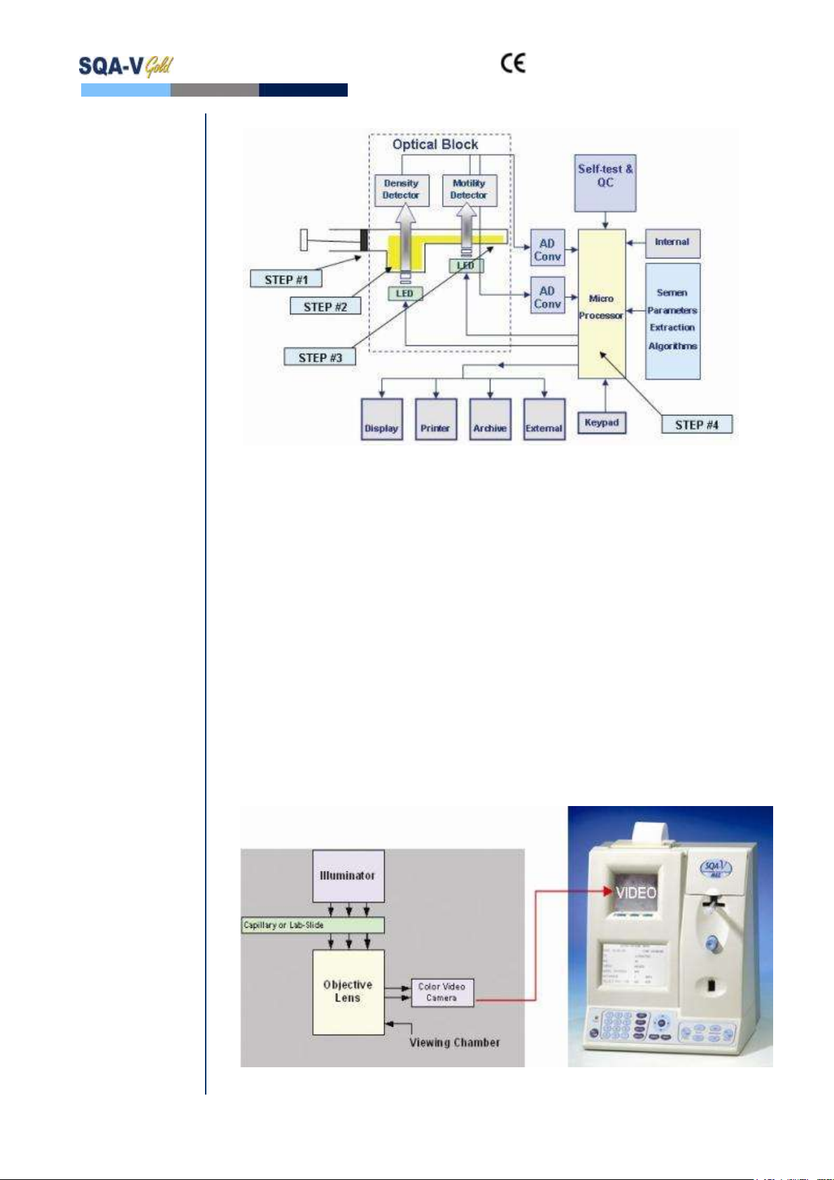
Technology
Automated System
Motility Channel
Light disturbances caused by moving sperm cells are detected and translated
into analog signal peaks.
The greater the number of motile sperm cells in the field of view, the higher
the peak.
The slower the sperm velocity the broader the signal peaks.
The average analog signal is mathematically proportional to MSC.
Concentration Channel
Sperm concentration is measured in the cuvette section of the SQA-V testing
capillary.
An infrared light wavelength specific to sperm cells is maximally absorbed by
sperm cells and minimally absorbed by other seminal fluid components.
In the final calculation of sperm concentration the SQA-V algorithm makes an
adjustment to account for the infrared light absorption of the seminal fluid
components.
and SQA-V Service Manual 24_Apr_2014
5
Step 1: The capillary is inserted into the measurement compartment.
Step 2: Sample concentration is evaluated in the "tall" 10 mm chamber of the
capillary by measuring the amount of optical absorption of light as a
beam traverses the seminal fluid.
Step 3: Motility is detected in the "thin" 0.3 mm section of the capillary by
analyzing light modulations caused by sperm motion.
Step 4: This information is then digitized and routed to the microprocessor that
applies algorithms to extract the required clinical semen parameters and
performs internal self-testing and calibration.
Visualization System
LED illuminator
Objective lens with zoom capability
Magnification: x300 to x500
Focal depth: Approximately 30 microns
Accommodates both a testing capillary and the SQA-V slide adaptor

and SQA-V Service Manual 24_Apr_2014
6
SECTION II: System Specifications
Sperm Quality
Analyzer
Dimensions: 40 Height x Width 30 x 15 - 25 cm Depth
Weight: 4.5 kg
AC power supply: 100 to 250 VAC, 50/60 Hz, 24W
Fuse rating: 2A 250V
Power stability requirements: Voltage fluctuations ± 5% nominal
Measurement Compartment
Sources of radiant energy - two LEDs for motility and spectrophotometry
channels
Detector system - two photo detectors - Motility and Optical Density
Visualization Compartment
LED illumination system
CCD, 330 TV lines
Objective: Standard, x20
Signal Output: PAL standard
Zoom system for magnification transition between x300 and x500
Focus regulator
Display(s)
Operational backlight LCD (16 lines x 40 characters)
Video backlight LCD (8 x 10 cm): Will automatically illuminate when unit is
“ON”
Use monitor ON/OFF key on the keypad to independently operate the video
display
Printer
Built-in, Dot Matrix
Non-thermostatic narrow paper with 20 characters per line
Ribbon cassette (Citizen)
Keypad
Operational keys: ON/OFF, TEST, PRINT, SERVICE, ARCHIVE, DELETE,
ENTER, four cursor buttons, ESC, ten numeric buttons (0-9)
Video control keys:ZOOM IN/OUT, ILLUMINATION HIGH/LOW, and
MONITOR ON/OFF
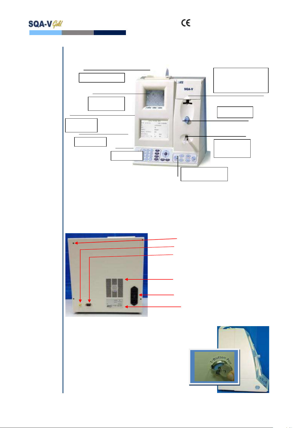
Front Panel
Built-in printer
Visualization compartment
LCD video display and controls
Focus knob
LCD operational display
Measurement compartment
Multi-button keypad
I-Button
Rear Panel
Power connector with fuse-holder (2 fuses: 250V, 2A)
Video connector
RS232 cable outlet

and SQA-V Service Manual 24_Apr_2014
7
Specimen Testing Supplies
Measurement capillary: Disposable, plastic, positive displacement testing
capillary. (Testing depth of capillary section: 300-micron; Cuvette section:
10 mm).
Standard laboratory slide: 20 micron depth, 22 x 22 mm cover-slip.
Operating System
Control: Keypad
Analysis Time: Normal Test –75 seconds; High Sensitivity/Postvasectomy
Test –5 minutes (9 minutes in version 2.43).
Software: Resides on flash memory and drives all man-machine interface
functions, runs algorithms for test measurements (according to WHO
guidelines), and operates visual and automated screens. System can be
upgraded from a PC CD-ROM.
Sample Testing Temperature: Calibrated for room temperature only
20-25° C / 68-77° F. Motility results will be impacted by heating the specimen.
Motility channel input signal: Analog, up to 5V.
Spectrophotometer channel input signal: Modulated (1 kHz) analog, up to
5V.
Quality Control
Internal: Electronic Self-Test and Auto-Calibration.
External: Counts can be run on the SQA-V automated and visualization
systems using commercially available assayed control material: "QwikCheck-
beads™" (product of Medical Electronic Systems) or Stabilized Sperm as a
non-assayed control in version 2.45 and higher.
PC Compatibility
Minimum requirements for V-Sperm software
PC: 1 GHz processor, Pentium 3
RAM: 256 MB
AGP-video display card with at least 16 MB of RAM memory
Video color: At least 16 bit (65,535)
CD ROM drive
200 MB free hard disk space for image capturing
Video resolution: Minimum 640 x 480
Operating system compatibility: Windows XP, VISTA (Windows 7 pending)
Ports: One serial; two USB ports
Monitor: 15" color
Required Software
V-Sperm software for SQA-V system and I-button set-up, archive and
CONTROL reporting also permits user to benefit from many features such as
real time visualization interface between PC and SQA-V visualization system,
data analysis, video/picture capture and archives test records.
Excel/Word for exporting files and clips
Operational Temperature and Humidity
System is operational at 15-38ºC.
NOTE: SQA-V operates in a wide range of ambient temperatures however the
system is calibrated to measure semen samples at room temperature:
20-25ºC (68-77ºF).

and SQA-V Service Manual 24_Apr_2014
8
NOTE: Variations in ambient temperature may impact the accuracy of test
results because of the effect of temperature on human semen.
System is fully operational at up to 80% humidity and 26°C.
Maintenance Schedule
Daily cleaning of measurement compartment (refer to User Guide –
"Cleaning") or with each 10-15 tests and/or spillage. USE ONLY the
MANUFACTURER supplied cleaning kit, brush and solution to clean the SQA-V
or the system may be damaged and/or inoperable!
Manufacturer Recommendations
Operate the SQA-V away from devices that may cause electronic noise (cell
phones) or other devices causing vibrations such as centrifuges.
Turn system OFF at the rear-panel when not in use for extended period of
time.
When running High Sensitivity or Postvasectomy tests do not interrupt test
cycle nor interfere with system or testing capillary in any way –this test
requires complete stability of the system during the 5 minute testing cycle.
Variations in ambient temperature can affect semen samples. The SQA-V
(HUMAN) is calibrated to test samples at room temperature: 20-25ºC (68-
77ºF). All VET SQA’s are calibrated with internal heaters.
Semen is considered a biologically hazardous material and is subject to
individual laboratory protocols for handling such materials.
Factory Default Settings
Chamber standard: 2 (Neubauer)
Morphology: WHO
Date format: DD/MM/YY
Time/Date: Manufacturer's local time/date
Controls (all levels/types): Exp date 01/01
and SQA-V Service Manual 24_Apr_2014
9
SECTION III: System Overview
SQA-V
System
NOTE: The
TEST button of
the SQA-V
keypad is only
active in the
CALIBRATION
mode
The ARCHIVE
button on the
keypad is
inactive- the
archive is
managed
through the
V-Sperm GOLD.
Keypad Navigation
Use NUMERIC keys to enter data; ARROW keys to move to the next field.
Press ENTER to select menu options, confirm data entries and to move to the next
screen or field.
Use the ESC button to return to the previous screen or field.
Rear Panel
Rear Panel
Side Panel
Side Panel
The side panel has an I-Button port (with
clip in newer SQA-V’s starting with Serial
Number 1333)
Refer to the Appendix Section for
instructions on how to load I-button tests.
Printer and paper
Prpaper
Visualization
compartment:
Accommodates both a
slide and the SQA-V
testing capillary
Automated
Measurement
compartment
Focus knob
Video display
and controls
Keypad
Operational
display
I-Button
Zoom magnification
X300 –X500
Rear panel assembly screws
Video output connector
RS232 COM port
Ventilation slots
Power connector and main
switch assembly
Instrument label

and SQA-V Service Manual 24_Apr_2014
10
Assemblies
The Chassis Assembly
The chassis assembly includes both the
base and rear panel and contains the
following sub-assemblies:
Main Board
Switch Power Supply
Surge Protector (starting with SN#
1270)
AC Power Inlet Assembly
Ventilation Fan
Printer
Communication Plug
Video Splitter
Video Board Assembly or T-Jack
Video Adaptor (starting with SN#
1318) or Video splitter (starting
with SN #1411)
The Cover Assembly
The cover assembly includes the following:
Operational Display
Video Keypad
Power Indicator LED
Visualization Compartment
Visualization Compartment Cover
Measurement Compartment
Focus Control
Schematic of the SQA-V Motherboard
SECTION IV: System Components and Accessories
Testing
Capillary
Testing Capillary
Can be used in both measurement chambers of the SQA-V.
Disposable, designed to collect and test samples in a biologically safe manner.
Motility is measured in the 0.3 mm (thin) "Capillary Section."
Concentration is measured in the 10 mm (tall) "Cuvette Section."
Main Board
LEDs Optical block
Zoom
Motor
Sensor
VIDMES
CCD
Visualization
LED
Monitor
control Display
Printer
DC Power
Supply
Keypad
Power switch
AC Power inlet
RS232
Inverter
(Backlighting)
(Flat cable)
Video
monitor
RCA
CCD card
J1
J9
J5
J2
J10J8 J16
J1
J5 J3
JP1
J14
J11
J13J17J7
JP1
JP5
JP6J1
J2
J1
J11
Fan
J10
J4
J6 J8 J6
J2
P1
P2
Mains
supply
Power
On/Off
LED
and SQA-V Service Manual 24_Apr_2014
11
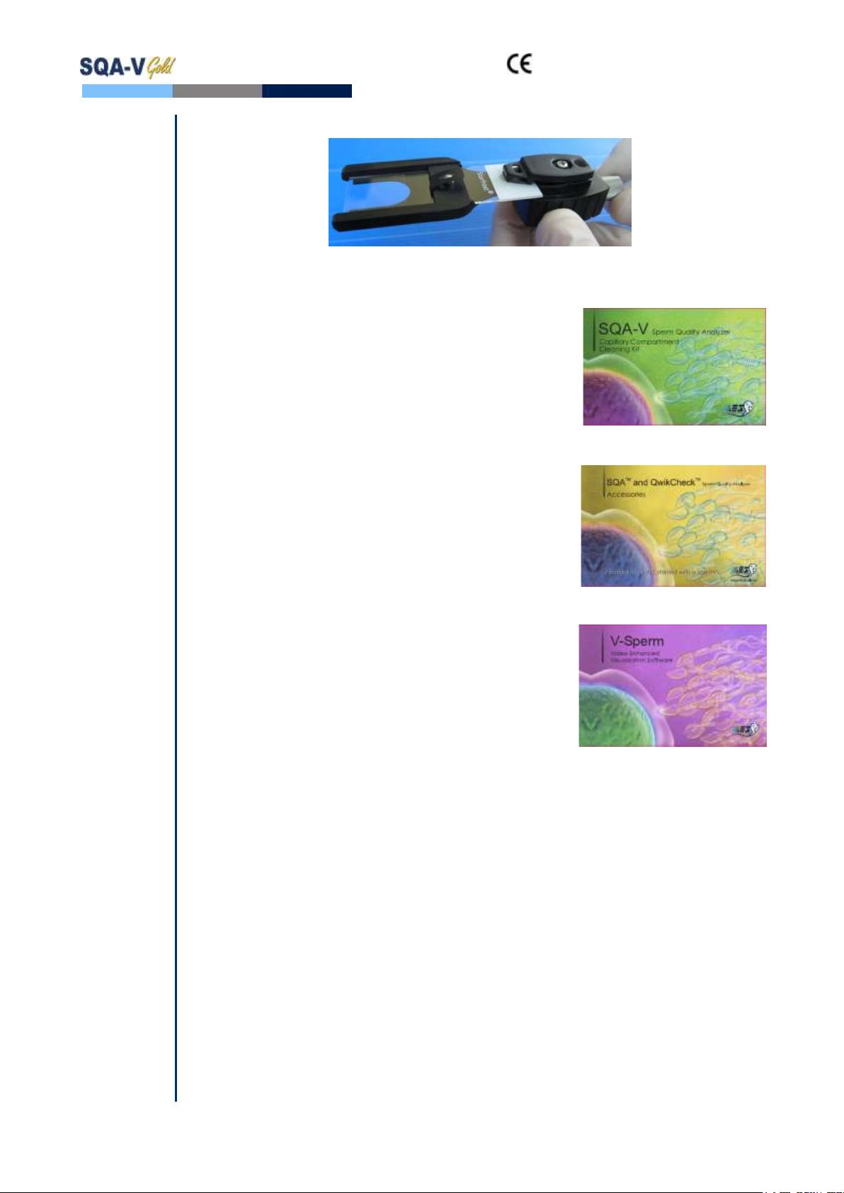
Slide
Adaptor
Slide Adaptor
For use with a standard laboratory slide 76 x 25.6 mm and 22 x 22 mm cover-slip
in the visualization compartment of the SQA-V to visually assess semen
samples.
Cleaning
Kit
Cleaning Kit
Daily cleaning is recommended or after testing 10-
15 specimens.
See the detailed cleaning instructions in the
Appendix Section.
NOTE: Only use the manufacturer’s cleaning kit or
the SQA-V can be damaged.
Accessory
Kit
Accessory Kit
Each kit contains:
Slide Adaptor
Power Cables
Communication Cable
Printer Paper
Printer Ribbon
Instructional Guides
V-Sperm
V-Sperm
Each kit contains:
V-Sperm CD
Security Key
RS232 to USB converter cable
Video Capture Device
User Guide
Electronic
SECTION V: Electronic Self-Test and Auto-Calibration
Self-Test
and Auto-
Calibration
A series of tests are automatically run on the SQA-V to check the calibration and
internal operating system. Tests are run when the SQA-V is first turned-on and
also prior to each semen analysis test.
Start-up:
Stabilization and auto calibration: Checks system stability and reference
ranges. The system sensors are analyzed for several minutes to insure that the
values are within a very narrow acceptable range. Once the system is stable for 30
seconds it will pass stabilization and auto calibration. The system will fail if it is not
stable for at least 30 seconds and a warning message will be displayed.
System noise: The level of electronic noise in the system is measured to insure
that noise thresholds are accurately defined to ensure effective measurement of
electronic signals. The system will use this measurement prior to running a test
and will automatically adjust the noise level thresholds to ensure accurate
readings.
Self-test: The system produces electronic signals that simulate motility and
concentration in order to check the performance of the system and verify that the
calibration settings are consistent with the factory specifications. The
SQA-V will report failures (see section on error and warning messages) and
"freeze" the system if the system is not within the established ranges.

and SQA-V Service Manual 24_Apr_2014
12
Prior to testing a sample:
Auto calibration verification: Reference values are read again. The
concentration and motility parameters are measured (without a testing capillary).
System noise: Measures the electronic noise level of the system to insure that
noise thresholds are accurately defined in the system to ensure effective
measurement of electronic signals. The system will use this measurement prior to
running a test and will automatically adjust the noise level thresholds to insure
accurate readings.
Electronic spikes: Checks for any measurement points that are out of range
electronically. More than three such points will fault the system and a warning
message will be displayed.
The following procedure details how the user can document the system
parameters to prepare for technical support if the system fails (see section of this
user guide on Error Messages and Warning Messages).
How to run a copy of the system parameters version 2.48/2.49 GOLD:
From the MAIN MENU select: SERVICE>PRINT SQA-V DEFAULT
SETTINGS>SELF TEST DATA
All other versions:
Remove any testing capillaries from the system.
Turn the SQA-V on from rear panel and from the front keypad.
When the MAIN MENU appears or when a FAILED SELF TEST message appears
press the SERVICE key on the keypad to enter the SERVICE menu.
Select USER.
Press the PRINT key on the keypad to generate the required printout.
Refer to the table below. Enter numbers in the "SQA-V Value" column that
corresponds to #1 - #10 from the SQA-V system parameters printout. Compare
the values. If the value from the SQA-V is within range mark the "Pass" column.
If not, mark the "Fail" column.
#
Parameter
Software version
2.45,2.46, 2.48,
2.49
SQA-V
Value
Pass
Fail
1.
Ref 1
150 –350 mV
2.
LED Cur 1
5 –25 mA
3.
Amplitude
50 –100 mV
4.
Zero Level
500 - 525
5.
Ref 2
2500 –3500 mV
6.
LED Cur 2
10 –32 mA
7.
CONC. 1
0 –1 M/ml
8.
CONC. 2
50-150 M/ml
9.
CONC. 3
300-600 M/ml
10.
Count (Internal
Data, Item
#12)
26 - 36
SECTION VI: Getting Started / Set-Up
Please refer to the relevant SQA-V User Guide for start-up and set-up instructions (based
upon the software version of the SQA-V).

and SQA-V Service Manual 24_Apr_2014
13
NOTE:
Turn off the
power supply
to the SQA-V
and disconnect
the power
supply cable
from the back
of the device
before opening
the SQA-V.
Only a
qualified, MES
certified
distributor is
authorized to
open the SQA-
V without
voiding the
warranty.
SECTION VII: Troubleshooting
Overview: The following sections describe how to troubleshoot and repair potential
problems that may occur with the SQA-V. Theses section will discuss how to provide
support for three types of issues: Technical - Self test - Clinical
PLEASE NOTE:
Only a qualified MES distributor who has been trained to perform technical
support is authorized to open the SQA-V.
If the SQA-V is opened without authorization it may cause damage to the
calibration AND will VOID THE WARRANTY.
The electro-optical board should NEVER be touched when the SQA-V is
opened –it will cause damage to the SQA-V calibration.
SECTION VIII: Technical Support/Part Replacement
Printer
Opening the SQA-V
Turn off the main switch located on the rear
panel and disconnect the SQA-V
from the electrical supply.
Using a Philips screwdriver, remove
all of the screws on the rear panel.
Closing the SQA-V
Grip each panel from the side and gently push
them back together making sure that all cables
and connectors are free and not “pinched”
between the panels.
Use a standard Phillips screwdriver to reconnect
the panels.
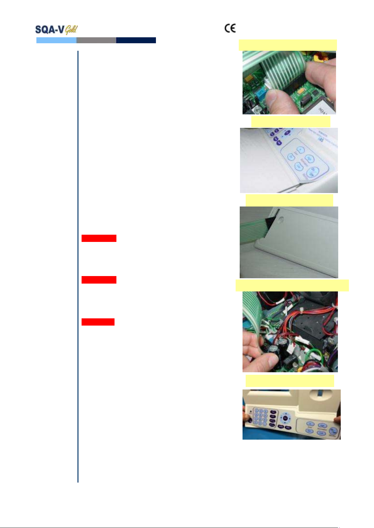
Printer (Part # PCD-0171)
ISSUE: The printer is not working
Open the SQA-V and check that the:
NOTE: Use
only paper
rolls supplied
by the SQA-V
manufacturer,
otherwise the
printer can be
damaged.
Printer has a roll of paper loaded properly
Printer ribbon (ink) is not dry
Printer paper is not jammed in the printer
Cable connecting the printer to the main
board is not damaged or disconnected.
Press the FEED button, if the paper does not
advance the printer needs to be replaced:
Pull the printer gently out of its holder
Disconnect the printer cable
Remove the two screws holding the printer
and remove the printer from the casing.
Replace the printer and re-attach it to the
SQA-V panel.
Remove the printer and
disconnect the cable
SQA-V Rear Panel
and SQA-V Service Manual 24_Apr_2014
14
Keypad
Please note: DO NOT connect it at this time.
Attach the keypad to its designated location on
the front panel by gradually removing the paper
while pressing it firmly into place from one side
to the other.
Please note: DO NOT bend the keypad during this
process or electrical wires/connectors will be
damaged.
Attach the keypad connector to the J11 location
on the main board.
Please note: The golden stripe on the cable
connector should face the rear panel (the fan side).
Close the SQA-V using 4 screws on the rear
panel of the SQA-V.
Disconnect the old Keypad Cable
Remove the old Keypad
Apply the New Keypad
Pull the old Keypad Cable
Attach the NEW Keyboard Connector
Keypad (Part # PCD-0201)
ISSUE: The Keypad is not working
Open the SQA-V
Verify that the keypad cable is connected
firmly to the Main board at J11 location
(connector is not loose)
Confirm that the cable is connected in the
correct orientation: The golden stripe on
the cable connector should be facing the
rear panel
If the cable is connected properly and the
keypad is still not working- replace the
keypad:
Disconnect the keypad cable connector from
location J11 on the main board
Using a flat screwdriver, carefully peel off the
damaged keypad from the front panel.
Clean the surface with alcohol and let it dry
for a few minutes.
Pull the keypad cable through the slit in the
front panel

and SQA-V Service Manual 24_Apr_2014
15
Power
Supply
Unit (PSU)
NOTES:
1. Turn off the
power supply
and disconnect
the power
supply cable
from the back
of the SQA-V
before
opening.
2. Refer to the
Appendix
section for
instructions on
how to address
power supply
problems.
Power Supply Unit –PSU
ISSUE: The main switch is ON but the power
indicator does not light up and the fan is not working.
Check the fuse in the fuse box located on the
rear panel of the SQA-V.
Replace the fuse if it is burned out.
Reconnect the power supply and turn the unit
back on.
If the unit still does not work, check the
input/output power inlet as instructed below.
How to check the input connector:
Check the voltage in the input connector of the
main PSU using a multimeter
OV: black wire
220V AC: red wire
If no power is evident, replace the power inlet
(see paragraph 7)
If power is being supplied to the input
connector, check the output connector.
Note:
Before
checking the
input\ output
connectors of
the main PSU,
turn on the
SQA-V from
the switch on
the rear panel.
Power
Supply Unit
(PSU)
How to check the output connector:
Disconnect the output cable from the
motherboard.
Check the voltage in the
output connector of the main PSU using a
multimeter:
0V: black wire
+5V: red wire
+12V: purple wire
-12V: white wire
If there is still no power supply in the output
connector, OR if the power is working but
the problem continues contact support
services.
Replacement of the Power Supply Unit –
ISSUE: The power supply and/or cables are not
working.
PLEASE NOTE: The instructions depend on the
SERIAL NUMBER (SN#) of the SQA-V.
SN# 1329 and less –follow the instructions in
SECTION 1
SN# 1330 and greater –follow the
instructions in SECTION 2
SECTION 1:
SN #1329
and lower,
PSU part #:
PSD-0492
1. Turn off the SQA-V and disconnect the power cable from the rear panel.
2. Place the SQA-V on its side; Using a #1.5 Philips screwdriver, remove the three screws
that connect the PSU to the rear panel. Open the SQA-V.
3. Remove the black plastic cover from the PSU.
Power Supply Board
Power Supply Power Cable
Unscrew the
Power Supply Unit (PSU)
and SQA-V Service Manual 24_Apr_2014
16
4. Disconnect the two cables of the OLD PSU:
Input connector- location P1
Output connector- location P2. This connector also includes the GROUND cable.
Remove the old PSU
5. Assemble the black Formex®cover to a new PSU
6. Secure the new PSU to the rear panel using the same three screws.
7. Re-connect the input and output cable connectors to the PSU.
8. Close the SQA-V. If the problem persists - Contact Customer Support.
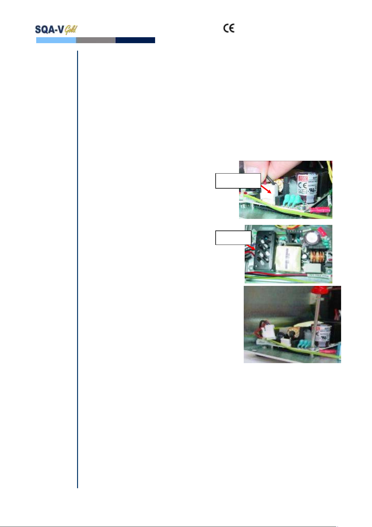
SECTION 2
SN# 1330
and above,
PSU part #:
FPE-E-
00146-00
1. Open the SQA-V.
2. Disconnect the input connector of the
power supply unit- location CN1.
3. Disconnect the output connector of the
power supply unit- location CN2.
4. Using a #2 Philips screwdriver, unscrew
the four screws that connect the PSU to
the rear panel.
5. Remove the old PSU.
6. Secure a new PSU to the rear panel using the same four screws.
7. Re-connect the input and output cable connectors to the PSU.
8. Close the SQA-V. If the problem persists - Contact Customer Support.
CN2 cable
connector
CN1 cable
connector
and SQA-V Service Manual 24_Apr_2014
17
Power
Inlet
Power Inlet (Part# AP-9081001)
ISSUE: There is no power supplied to the PSU from the inlet.
NOTEs:
1. Turn off the
power supply
and disconnect
the power
supply cable
from the back
of the SQA-V
device before
opening.
2. Refer to the
Appendix
section for a
flow chart of
power supply
problems and
solutions.
Open the SQA-V.
Unscrew the power-inlet screws at the rear
panel of the device.
Disconnect the power supply connector from
the power supply board.
Gently pull the plastic cover of the power inlet
until the connectors are exposed.
Disconnect the three connectors from the
power inlet.
Gently pull the power inlet out of the SQA-V
through the rear panel.
Insert a new power inlet and re-connect the
cables.
Re-connect the internal cables, re-place the
internal cover and re-connect the power supply
cable to the power supply board.
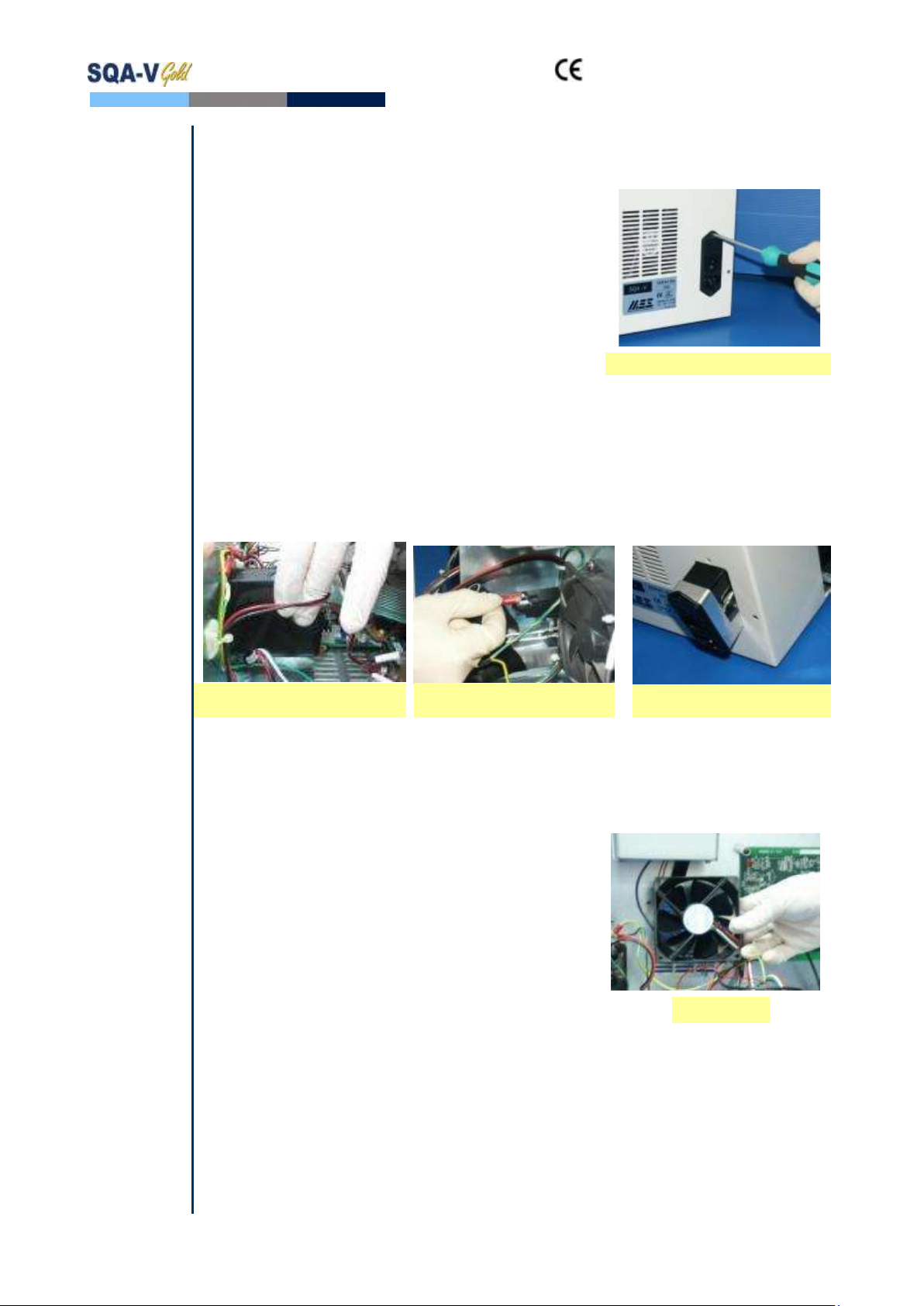
Fan
Assembly
Fan Assembly
For SQA-V of SN 1329 and lower: use part# KHD-08-000856
For SQA-V of SN 1330 and higher: use part #V-H-00575-00
ISSUE: The master switch is ON, the power indicator is lit but the fan is not rotating.
Please note:
The fan on
veterinary
systems work
only when the
system
reaches a
certain internal
temperature.
Please note:
Be sure to re-
connect the
cables
correctly and
verify that the
GROUND
cables are
attached VERY
tightly.
Open the SQA-V.
Confirm that all the fan connecting cables are
in place.
Check that the voltage in the main board
connector of the fan (location JP1) is:
0V: black wire
+12V: purple wire
If no power is evident, replace the main PSU
(see paragraph 6)
If the voltage is as described above, replace
the fan:
Unscrew the four fan screws.
Replace the fan assembly (fan+ cable).
Re-connect the cables and screw the
new fan to the rear panel of the SQA-V.
Do not change the direction of the
outlet air flow! (the arrow on the fan
should point outwards)
Pull the plastic cover to expose
the connectors
Disconnect the 3 connectors
from the power inlet
Gently pull the power inlet
from the rear panel
SQA-V Fan
Unscrew the power inlet screws

and SQA-V Service Manual 24_Apr_2014
18
Operation
Monitor
Operation Monitor - Lower LCD Screen (Part# LCD-0009)
ISSUE #1: The SQA-V is ON, both power indicators are functioning and the fan is
working. But the lower LCD screen (Operation Monitor) is not illuminated although data is
displayed on the screen.
NOTE: Turn
off the power
supply to the
SQA-V and
disconnect the
power supply
cable from the
back of the
device before
opening the
SQA-V.
Open the SQA-V.
Turn on the SQA-V and check that the
LCD Backlight is lit. If not, check the
input and output cables of the
inverter board: verify that the cables
are well connected and not loose.
If the power supply is OK and the
screen doesn’t light up, replace the
inverter board (Item#AS-9084111):
Turn the SQA-V off and
disconnect the cables
connecting the inverter board
to the main board and LCD
screen.
Using a Phillips screwdriver,
remove the two screws that
secure the old inverter board.
Replace the inverter board
with a new one and secure it
with the two screws.
Re-connect the cables of the
inverter board.
If the problem persists, contact MES
Customer Support.
WARNING:
The two ends
of the flat
cable must be
connected in
the same way
at each of the
hubs or the
LCD may be
burned!
ISSUE #2- Blank Screen: There is no data displayed on the screen in spite of the fact
that the SQA-V is ON, both power indicators are functioning and the fan is working.
Re-install SQA-V software.
If the software was not installed successfully- please refer to the technical bulletin in
the appendix section for further instructions
If the software was installed successfully and the problem remains- check the LCD
flat cable:
Open the SQA-V and verify that the LCD flat cable, with the red lined side up
is connected to the section designated with a 12 on the main board
Replace the flat cable if it appears damaged in any way.
If replacing the cable does not work- replace the processor on the main board (see
Appendix section for instructions).
LCD Operation
Monitor/Board
LCD Backlight
Inverter Board
Power Cables
LCD Flat
Cable
WARNING: DO
NOT TOUCH the
illuminated area
of the LCD
Backlight –HIGH
VOLTAGE is
supplied there.
AFTER checking
the LCD backlight,
turn off the
SQA-V and
disconnect it from
the main.
Note the alignment of
the RED line on the cable

and SQA-V Service Manual 24_Apr_2014
19
Note: for
more detailed
explanations
regarding
blank screen
issues, please
refer to the
“blank screen
technical
bulletin” in the
appendix
section
If replacing the processor does not work:
Re-start the SQA-V and see if the LCD operational screen is still blank. If yes,
replace the screen:
Disconnect the operational display data and power cable - note the four
screws.
Replace the screen & reconnect the data and power cables.
In case the problem persists after replacing the LCD screen- contact MES Customer
Support.
Focus Knob
Focus Knob (Part# PE-MA-00538-00)
ISSUE : When using the focus knob there is no change in the visualization system (the
focus shown on the video screen is not changed).
Open the SQA-V and disconnect the optical assembly from the front panel (four
screws)
Disconnect the focus knob from the optical assembly by unscrewing three screws
Remove the old focus knob
Insert the new focus knob making sure it is turned all the way counterclockwise
before replacing
Re-connect the optical assembly to the front panel and close the SQA-V
Data Cable
Disconnect the
focus knob
Replace the
focus knob
New, Improved focus knob
Remove the four screws
New Operational Display

and SQA-V Service Manual 24_Apr_2014
20
Video
Video Screen (Part# LCD-0010)
ISSUE: A problem in the video system occurs when there is a malfunction or
maladjustment in one of these areas:
Light source, CCD camera, Harness connection, Video display monitor
To diagnose a video system problem, refer to the table below. Detailed instructions on
how to repair the problem are presented after the table.
Description of the
Video Problem
VIDEO Troubleshooting/Repair
1. Poor resolution
and dark pictures on
both the SQA-V and
V-Sperm monitors,
OR no image on both
SQA-V and V-sperm
1. Check to make sure the illumination setting of the SQA-V
is on high and the brightness setting is maximized to the
best setting. Intermittently press the illumination button on
the keypad –do not press and hold.
2. Turn the illumination button (this is the one of the blue
buttons under the video screen) since it may be set on no
illumination
3. Check the brightness settings in V-Sperm: Go to
VIDEO>Real Time Video>Settings - adjust brightness to the
best setting
4. If no improvement, check the visualization LED, if the light
indicator is on, it is working.
5. If no light is visible through the light indicator, replace the
visualization LED cable- part # KHD-908-000849-03
(detailed instructions can be found after this table).
6. If the LED is working- check the cable connecting the optical
column to the MB and to the video splitter/video adaptor/
video board:
Open the SQA-V
Check to see if all of the harness connections are secure
and tightly connected.
Check the voltage on the main board at location J9 using a
multimeter- the voltage value should be 12V. Make sure to
measure the voltage between the green and the black
wire.
If the voltage is different than 12V- replace the cable (part
# KHD-908-000853).
If the same problem persists after replacing the cable-
replace the CCD camera (part #5226, see instructions in
this manual).
Light indicator
Other manuals for SQA-V Gold
2
This manual suits for next models
1
Table of contents
Other MES Medical Equipment manuals


