MES SQA-Vision User manual

V e r s i o n 1 0 9 . 1 3 . 4
C a t a l o g # : V S - M L - 0 1 0 9 1 - 0 0
R e v : J a n 2 0 2 0

SQA-Vision
Service Manual Version 109.13.4
Edition rev.: Jan 2020 2
Table of
Contents
SECTION I: Introduction
Automated Test Results 3
Tec nology 4
SECTION II: System Specifications and Requirements
Sperm Quality Analyzer – SQA-Vision 5
SECTION III: System Overview
Front Panel 7
Rear Panel 7
Side Panel 8
T e C assis Assembly 8
T e Cover Assembly 8
Sc ematic of t e SQA-Vision Mot erboard 8
SECTION IV: System Components and ccessories
Testing Capillary 9
Cleaning and Accessories Kit 9
SECTION V: Self- Test and uto-Calibration
Start Up 9
Prior to testing a sample 10
SECTION VI: Getting Started / Set Up
Getting Started / Set Up 10
SECTION VII: Troubleshooting
Overview 11
SECTION VIII: Technical Support and Part Replacement Instructions
Opening t e SQA-Vision 11
Closing t e SQA-Vision 11
Keypad 12
Power issues 13
Power Supply Unit (PSU) 13
Power Inlet 14
Fan Assembly 14
Operation Monitor (LCD Screen) 15
Focus Knob and Field Of View Knob 18
Surge Protector Replacement 18
Capillary Sensor Troubles ooting and Replacement 19
Camera Replacement 21
Optical Board to LED Cable Replacement 23
SECTION IX: ppendixes
C
leaning t e
SQA
-
Vision
2
4
Replacing t e Processor
2
5
Power Supply Troubles ooting Flowc art
2
7
Parameters Out Of Range: Troubles ooting 28

SQA-Vision
Service Manual Version 109.13.4
Edition rev.: Jan 2020 3
SECTION
I
: Introduction
T e SQA-Vision is a ig -performance PC-based analytical medical device t at combines
tec nology in optoelectronics, computer algorit ms and video microscopy. T e SQA-Vision and
a fully integrated TOUCH-SCREEN work
toget er to provide user friendly semen analysis testing.
Samples are run in t e SQA-Vision testing device and all data entry and user interface is
computer based.
FRESH, POSTVASECTOMY, WASHED, SWIM-UP, DENSITY GRADIENT and FROZEN semen
samples as well as LONGEVITY testing can be performed on t e SQA-Vision. Additionally MANUAL
testing can be performed utilizing t e on-screen MANUAL COUNTER. T e ig resolution
visualization component of t e SQA-Vision permits assessment of oligospermic specimens and
poor quality IVF samples.
W en results fall below t e automated dynamic range of t e system, a LOW QUALITY COUNTER
opens automatically to permit manual sperm counting. Debris and round cell assessment is
performed using t e DEBRIS/ROUND CELLS SCANNER. % Normal morp ologically is assessed
automatically along wit ot er semen parameters. Vitality and Morp ology differentials can be
assessed manually using t e en anced visualization system and on-line counters.
T e analysis time varies according to t e type of sample being tested: Normal quality samples –
75 seconds; Low quality – 2 additional minutes; Post vasectomy – 5 minutes.
T e system runs a self-test and auto-calibration upon start up. It also runs latex beads or
stabilized sperm external quality controls.
utomated
Test Results
and
Reportable
Range
utomated Test
Results
Concentration M/ml Motile Sperm Concentration (MSC)
M/ml
Total Motile
PR+NP % Progressively Motile Sperm Concentration
(PMSC)
M/ml
Progressive PR %
Functional Sperm Concentration (FSC)
(Progressively motile sperm wit normal
morp ology)
M/ml
Non-progressive
NP % Velocity
mic
/sec
Immotile IM % Sperm Motility Index (SMI)
#
Normal forms
(WHO 5
t
) %
TOT LS PER SEMEN VOLUME
Sperm #
M/ejac
Functional Sperm
M/ejac
Motile Sperm
M/ejac
Morp ologically Normal Sperm
M/ejac
Progressively
Motile Sperm
M/ejac
POSTV SECTOMY
Motile, Immotile
and Total Sperm M/ml # Motile, # Immotile and # Total
Sperm/semen volume M

SQA-Vision
Service Manual Version 109.13.4
Edition rev.: Jan 2020 4
Technology
utomated System
Motility Channel
Lig t disturbances caused by moving sperm cells are detected and translated into
analog signal peaks.
T e greater t e # of motile sperm cells in t e field of view, t e ig er t e peak.
T e slower t e sperm velocity t e broader t e signal peaks.
T e average analog signal is mat ematically proportional to MSC.
Concentration Channel
Sperm concentration is measured in t e cuvette section of t e SQA-testing capillary.
An infrared lig t wavelengt specific to sperm cells is maximally absorbed by sperm
cells and minimally absorbed by ot er seminal fluid components.
In t e final calculation of sperm concentration, t e SQA-Vision algorit m makes an
adjustment to account for t e infrared lig t absorption of t e seminal fluid components.
SQ -Vision Reportable Range ( utomated Results)
Sample
Type
Sperm
Conc.
M/ml
Motility
%
Morp
%
MSC
M/ml
PMSC
M/ml
Motile /
Immotile /
Total Sperm
M/ml
Fres <2 - 400 0 - 100 2 - 30 <0.2 -
400 0 - 400
-
Was ed <2 -
200+ 0 - 100 2 - 30 <0.2 -
200+
0 -
200+ -
Swim-up,
Density
Gradient,
Frozen
- - - <0.2 -
200+
0 -
200+ -
Post-Vas - - - - - 0 - 400
#1: T e capillary is inserted into t e measurement compartment.
#2: Sample concentration is evaluated in t e "tall" 10 mm c amber of t e capillary by
measuring t e amount of optical absorption of light as a beam traverses the
seminal fluid.
#3: Motility is detected in t e "t in" 0.3 mm section of t e capillary by analyzing light
modulations caused by sperm motion.
#4: T is information is t en digitized and routed to t e microprocessor t at applies
algorit ms to extract t e required clinical semen parameters and performs internal
self-testing and calibration.

SQA-Vision
Service Manual Version 109.13.4
Edition rev.: Jan 2020 5
SQ
-
Vision
SECTION
II
: System Specifications and Requirements
Dimensions: 32 X 30 X 24 cm
Weig t: 7 Kg
AC power supply: 100-240 VAC, 50-60 Hz, 20 VA
Front Panel
Displays: LCD display
Testing: Measurement and Visualization compartments
Ot er: Multi-button keypad, Focus knob, FOV (Field Of View) knob
Keypad
Operational keys: I-Button, Service, Enter, Esc, Delete, four cursor buttons and ten
numeric buttons (0-9).
Video control key: Zoom In/Out
Measurement Compartment
Sources of radiant energy - two LEDs for motility and concentration c annels
Detector system - two p oto detectors - Motility and Optical Density
Operating System
nalysis Time: Normal Test – 75 seconds; Low Quality – 2 additional minutes;
Postvasectomy (automated) – 5 minutes
Software: Resides on flas memory. System can be upgraded from a PC CD-ROM
Motility channel input signal: Analog, up to 5V.
Concentration channel input signal: Modulated (kHz) analog, up to 5V.
Rear Panel
Power inlet w/fuse- older (fuses: 250V,2A), RS232 connector, 2 USB 2.0 B-Type Male,
On/Off switc of t e blue surrounding LEDs (located on bottom side of t e panel).
Left Side Panel
Power On/Off switc
I-Button port
Visualization Compartment
W ite LED illumination system wit max luminous intensity – 35,000 mcd.
Digital Camera, max resolution: 1280 x 1024 pixels, ig resolution of "live" and "frozen"
images provided by capturing a ig # of FPS (frames per sec).
Objective: Standard, x40, c romatic aberration correction.
Zoom system for smoot magnification transition between x1188 and x1725
Focus adjustment knob
Field of View Stage knob
SQ -Vision
Maintenance Schedule
Daily: Clean measurement compartment daily w en running samples and after every 10-
15 tests and/or for ANY spillage. Follow manufacturer’s cleaning instructions using
manufacturer cleaning kit (Refer to t e appendix section “Cleaning t e Capillary
Compartment” in t is User Guide).
ONLY use the Manufacturer’s cleaning kit and cleaning brush or damage will
occur to the SQ -Vision film and the system will not operate!
Manufacturer Recommendations
Operate t e SQA-Vision away from devices t at may cause electronic noise or ot er
devices causing vibrations suc as centrifuges.

SQA-Vision
Service Manual Version 109.13.4
Edition rev.: Jan 2020 6
Turn t e system OFF w en not in use for an extended period of time.
W en running Postvasectomy tests do not interrupt test cycle nor interfere wit system
or testing capillary in any way – t is test is ig ly sensitive to any motion and requires
complete stability of t e system during t e 5-minute testing cycle.
Variations in ambient temperature can affect semen sample parameters. It is essential
that semen samples are not heated for testing. T e SQA-Vision is calibrated to conduct
tests at room temperature: 20-25ºC (68-77ºF).
Semen is considered a biologically hazardous material and is subject to
individual laboratory protocols for handling such materials and at a minimum:
Laboratory coat, mask and gloves for operating personnel protection
Samples andling and waste disposal in specially marked azardous waste containers
Only personnel trained to work wit biologically azardous materials suc as semen
s ould be testing and andling semen
Operating Temperature and Humidity
Maximum operational umidity is up to 80% for temperatures of up to 31
º
C wit
decreasing linearly to 50% at 38
º
C.
Operates in a wide range of ambient temperatures (15-38
º
C) owever t e system is
calibrated to measure semen samples at room temperature:
20-25
º
C (68-77
º
F). Note: Extreme ambient temperature may impact t e accuracy of
motility test results because of t e known effect of temperature on uman semen.
Operational Environmental conditions:
System is intended for indoor use at a maximum altitude of 2000m, mains supply
fluctuations ±10%, Overvoltage Category II, Pollution Degree II.
PC / Hardware
PC and device: "All in One" - computer wit SQA-Vision software and device.
Quality Control
Internal: Electronic Self-Test and Auto-Calibration. Runs automatically upon start-up.
Besides t at, reference values are verified prior to eac test.
External: Runs QC samples daily prior to testing or per laboratory protocol. Runs assayed
latex bead control: "QwikCheck™-beads" (product of Medical Electronic Systems) for
concentration and negative control for motility/concentration OR non-assayed: Latex
beads or stabilized sperm CAP or NEQAS for concentration.
Sample Testing
Sample Testing Temperature: Calibrated for room temperature only. Motility results
will be impacted by eating t e specimen (not recommended).
System calibrated to test Human semen and specified Control samples only. Not
for use wit animal semen.
SQ -Vision measurement capillary: Disposable, plastic, testing capillary. Requires
500 µl of sample for normal volume testing, 20 µl for low volume testing, 300 µl for diluted
mode. Use only manufacturers’ certified testing capillaries in t e automated system.
Field of View Stage: T is stage is an integral part of t e SQA-Vision visualization
compartment. Vision™ fixed cover slip slides (obligatory for accurate test results w en
manual sperm counting is required), standard slides (for debris scans and image
capturing) are accepted in t e field of view stage using t e supplied slide older.

SQA-Vision
Service Manual Version 109.13.4
Edition rev.: Jan 2020 7
SQ -Vision
Overview
S
ECTION
III: System Overview
Front Panel
Keypad Navigation
Use NUMERIC keys to enter data; RROW keys to move to t e next field.
Press ENTER to select menu options, confirm data entries and to move to t e next screen
or field.
Use t e ESC button to return to t e previous screen or field.
Rear Panel
Rear Panel
Operation Display
I-Button
Keypad
Automated
Measurement
Compartment
Focus Knob
Field of View Knob
Visualization
compartment accepts
eit er fixed coverslip
slides or standard
slides (Zoom
magnification
1188X÷1725X)
RS232 COM Port
USB Data Port
USB Video Port
Rear Panel
Assembly Screws
(x4)
Ventilation Slots
Power Inlet
Product Label
Power indication LED
SQA-Vision
Service Manual Version 109.13.4
Edition rev.: Jan 2020 8
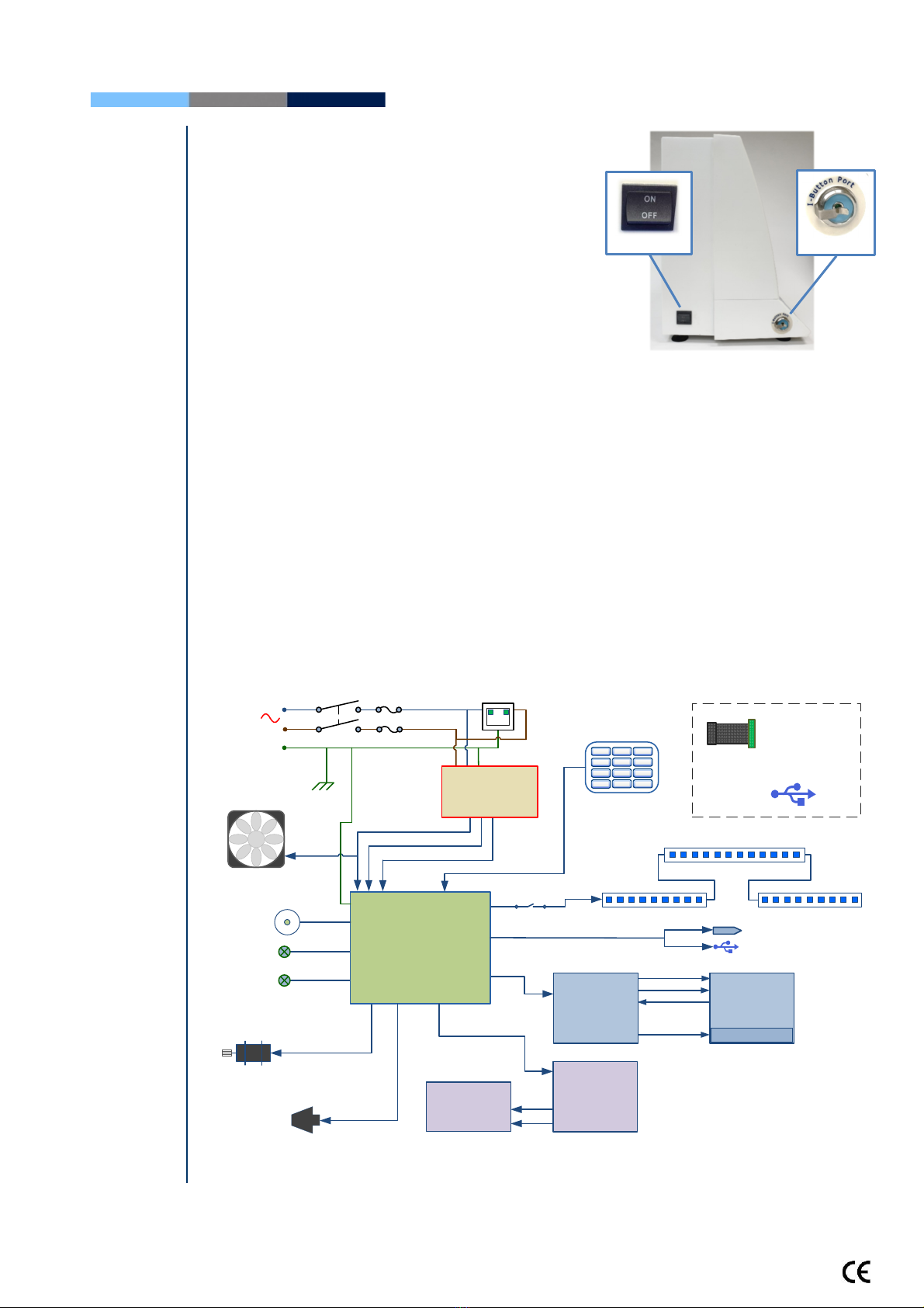
Side Panel
Side
Panel
T e side panel as an I-Button port wit
spring clip
(Refer to t e Appendix instructions on ow to
load I-button tests)
T e side panel also includes t e On/Off switc
ssemblies
The Chassis ssembly
T e c assis assembly includes bot t e
base and rear panel and contains t e
following sub-assemblies:
Main Board
Switc Power Supply
USB outlets
Surge Protector AC Power Inlet
Assembly
Ventilation Fan
RS232 Communication port
The Cover ssembly
T e cover assembly includes t e following:
Operational Display
Keypad
Power Indicator LED
Visualization Compartment
Measurement Compartment
Focus Control
Field of View control
Motherboard
Schematic
Schematic of the SQ -Vision Motherboard
+5 VDC
+3 VDC
+12 VDC
+2 VDC
AC
100-230 V,
50/60 Hz
+12 VDC
+5 VDC
-12 VDC
+12 VDC
Mother Board
Fuse
2A x 2
On/Off LED
Visualization LED
Chassis
JP1
GND
J8
J10
+12 VDC
J17
J14
J1
J7
I-Button Port
J18
7 8 9
F0 .
1 2 3
45 6
J11
Keypad
J13
+1.7 VDC
Capillary
sensor
Surge
protector
CN1
CN2
FAN
DC Motor
Switch
Main switch
Vision video
camera USB
2.0
Notes:
SQA-Vision video
camera receives the
power from PC’s USB
port and doesn’t have
a connection to
device’s Motherboard
+5 VDC
Main
Power Supply
LED’s Board
J2
J1
+1.5 to +1.8 VDC
+1.5 to +1.8 VDC
Optical Board
JP1
JP5
JP6
Operational
Monitor
Backlight LEDs
-16 VDC
-13 VDC
+5 VDC
+3.5 VDC
Backlight PCB
J1 J2
J3
RS232 Port
USB Data Port
Decorative LEDs
J5
I-Button
On/Off switch

SQA-Vision
Service Manual Version 109.13.4
Edition rev.: Jan 2020 9
SECTION IV: System Components and ccessories
Testing
Capillary
Testing
Capillary
Can be used in bot measurement c ambers of t e SQA-Vision.
Disposable; designed to collect and test samples in a biologically safe manner.
Motility is measured in t e 0.3 mm (t in) "Capillary Section."
Concentration is measured in t e 10 mm (tall) "Cuvette Section."
Cleaning Kit
Cleaning Kit
Daily cleaning is recommended or after testing 10-
15 specimens.
See t e detailed cleaning instructions in t e
Appendix Section.
Note: Only use t e manufacturer’s cleaning kit or
t e SQA-Vision can be damaged.
ccessories Kit
ccessories
Kit
Eac kit contains:
Power Cables
Communication Cable
USB cables
RS232 cable
RS232 to USB converter
Instructional Guides
Slide older
Additional set of device feet
Barcode reader
Capillary piston – Opening and Removal Jig
Self-Test and
uto-
Calibration
Start-up
Section V: Self-Test and uto Calibration
The SQ -Vision automatically runs a series of tests to check calibration settings and the
internal operating system. Tests are run when the system is turned on and prior to
testing a sample.
Start-up:
Stabilization and autocalibration: C ecks system stability and reference parameters.
T e system sensors are analyzed for several minutes to ensure t at t e reference
parameters are wit in acceptable ranges. Once t e system is stable for 30 seconds it will
pass stabilization and autocalibration. A warning message of t e system stabilization

SQA-Vision
Service Manual Version 109.13.4
Edition rev.: Jan 2020 10
Service
Parameters
failure will be displayed if it is not stable for at least 30 seconds and t e reference
parameters are not wit in acceptable ranges.
System noise: Measures t e electronic noise level of t e system to insure effective
measurement of electronic signals.
Self-test: T e system produces electronic signals t at simulate motility and concentration
measurements in order to c eck t e performance of t e system and verify t at t e
calibration settings are consistent wit t e factory specifications. T e SQA-Vision will
report t e Self-Test failure (see section on error and warning messages) if t e system is
not wit in t e establis ed Self-Test ranges.
Prior to testing a sample:
utocalibration verification: Reference parameters of t e concentration and motility
c annels are measured again (wit out a testing capillary).
System noise: Measures t e electronic noise level of t e system to insure effective
measurement of electronic signals. Prior to running a test, t e SQA-Vision will
automatically adjust t e noise level t res old to insure accurate readings.
Electronic spikes: C ecks for measurement points t at are out of range electronically
and displays a warning message if out of range.
Instructions for printing the SQ -Vision SERVICE parameters to prepare for technical
support:
If a Self-Test failure occurs, t e related status icon in t e HOME screen will turn red:
Click: SELF-TEST ST TUS icon to open a warning message wit instruction on ow to
resolve t e problem:
Click: REPORT from t e HOME or SERVICE screen to generate a
SERVICE REPORT.
T is may be required for troubles ooting and tec nical support.
SECTION VI: Getting
Started / Set
-
Up
(Refer to t e User Guide)

SQA-Vision
Service Manual Version 109.13.4
Edition rev.: Jan 2020 11
Troubleshooting
SECTION VII: Troubleshooting
Overview: T e following sections describe ow to troubles oot and repair potential problems
t at may occur wit t e SQA-Vision. T eses section will discuss ow to provide support for
t ree types of issues: Technical - Self test - Clinical
PLE SE NOTE:
Only a qualified, technical support trained MES distributor is authorized to open
the SQ -Vision.
If the SQ -Vision is opened without authorization it may cause damage to the
calibration ND will VOID THE W RR NTY.
The electro-optical board should NEVER be touched when the SQ -Vision is
opened – it will cause damage to the system’s calibration.
Technical
Support and
Part
Replacement
SECTION VIII: Technical Support/Part Replacement
Opening the SQ -Vision
Turn off t e main switc located on t e side panel and
disconnect t e SQA-Vision from t e electrical supply.
Using a P ilips screwdriver, remove
all screws on t e rear panel.
Closing the SQ -Vision
Grip eac panel from t e side and gently pus t em
back toget er making sure t at all cables and
connectors are free and not “pinc ed” between t e
panels.
Use a standard P illips screwdriver to reconnect t e
panels.

SQA-Vision
Service Manual Version 109.13.4
Edition rev.: Jan 2020 12
Keypad
Keypad (Part #
VS
-
E
-
00851
-
00)
ISSUE: The Keypad is not working
Open t e SQA-Vision
Verify t at keypad cable is connected firmly to
connector J11 on t e Main board (connector is not
loose)
Confirm t at t e cable is connected in t e correct
orientation: T e golden wide stripe on t e cable
connector s ould be facing t e rear panel
If t e cable is connected properly and t e keypad is still
not working- replace t e keypad:
Disconnect t e keypad cable connector from location
J11 on t e Main board
Using a flat screwdriver, carefully peel off t e damaged
keypad from t e front panel. Clean t e surface wit
alco ol and let it dry.
Pull t e keypad cable t roug slit in t e front panel
Please note:
DO NOT connect it currently.
Attac t e keypad to its designated location on t e
front panel by gradually removing t e paper w ile
pressing it firmly into place from one side to t e ot er.
Please note: DO NOT bend the keypad during this
process or electrical wires/connectors will be
damaged.
Attac t e keypad connector to t e J11 location on t e
main board.
Please note: The golden stripe on the cable connector
should face the rear panel (the fan side).
Close t e SQA-Vision using 4 screws on t e rear panel of t e
device.
Verify connection of
Keypad
Peel off the damaged
Keypad
ttach the NEW Keyboard
Connector
pply the New Keypad

SQA-Vision
Service Manual Version 109.13.4
Edition rev.: Jan 2020 13
Power
issues: fuses,
PSU, power
inlet
Notes:
1.Turn off t e
power supply
and disconnect
t e power
supply cable
from t e back of
t e SQA-Vision
before opening.
2.Refer to t e
Appendix section
for instructions
on ow to
address power
supply problems.
Note:
Before c ecking
t e input\ output
connectors of t e
main PSU, turn on
t e SQA-Vision.
Power issues
-
fuses, PSU
,
power inlet.
ISSUE: T e main switc is ON, but t e power indicator
does not lig t up and t e fan is not working
C eck t e fuses in t e fuses box located on t e rear
panel of t e SQA-Vision.
Replace t e fuse if it is burned out.
Reconnect t e power cord and turn t e unit back on.
If t e unit still does not work, c eck t e input/output
voltage of PSU as instructed below.
How to check the input voltage of PSU:
C eck t e voltage on t e input connector of t e main
PSU using a multimeter
T e voltage s ould be ≈220V AC between t e
black and t e red wires
If no voltage is evident, replace t e power inlet (see
t e relevant section below)
If voltage is being supplied to t e input connector,
c eck t e output connector.
How to check the output voltage of PSU:
Disconnect t e output cable from t e mot erboard.
C eck t e voltage on t e output connector of t e main
PSU using a multimeter:
0V: black wire
+5V: red wire
+12V: purple wire
-12V: w ite wire
If t ere is no voltage on t e output connector or t e
voltage is not correct, please replace t e main PSU as
instructed below
If t e problem persists, please contact Customers
Support.
Replacing the Power Supply Unit –
part #Fpe-E-00146-00
ISSUE: T e power supply and/or cables are not working
Open t e SQA-Vision.
Disconnect t e input connector of t e power supply
unit- location CN1.
Disconnect t e output connector of t e power supply
unit- location CN2.
Using a #2 P ilips screwdriver, unscrew t e four
screws t at connect t e PSU to t e rear panel.
Remove t e old PSU.
Secure a new PSU to t e rear panel using t e same
four screws.
Re-connect t e input and output cable connectors to
t e PSU.
Power Supply
Unit (PSU)
Fuses box
Power Supply Unit
PSU Input connector
Power Supply Output Cable
Unscrew 4 screws of PSU
SQA-Vision
Service Manual Version 109.13.4
Edition rev.: Jan 2020 14
Close t e SQA-Vision. Reconnect t e power cord and
turn t e unit back on. If t e problem persists -
Contact Customers Support
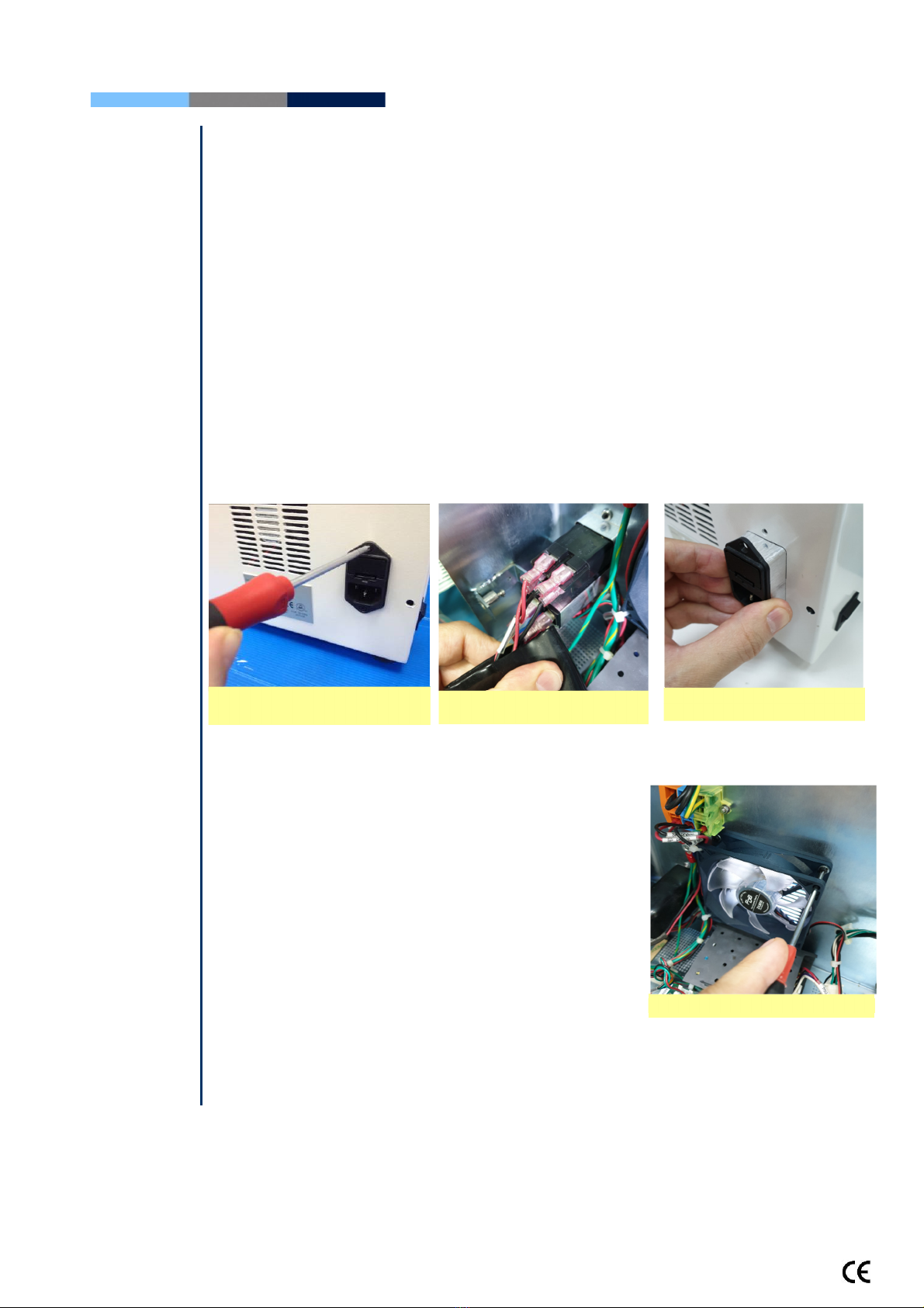
Power Inlet
Notes:
1. Turn off t e
On/Off switc and
disconnect t e
power cord from
t e SQA-Vision
before opening.
2. Refer to t e
Appendix section
for a flow c art of
power supply
problems and
solutions.
Power Inlet (Part# VS
-
E
-
00850
-
00)
ISSUE: T ere is no voltage supplied to t e PSU from t e inlet.
Open t e SQA-Vision.
Unscrew t e power-inlet screws at t e rear panel of t e device.
Disconnect t e power supply connector from t e power supply board.
Gently pull t e rubber cover of t e power inlet until t e connectors are exposed.
Please note ow all connector are connected to t e power inlet.
Disconnect all connectors from t e power inlet.
Gently pull t e power inlet out of t e SQA-Vision t roug t e rear panel.
Insert a new power inlet and re-connect t e cables.
Re-connect t e internal cables, re-place t e internal cover and re-connect t e power
supply cable to t e power supply board.
Fan ssembly
Fan ssembly (part # V
-
H
-
00575
-
00)
ISSUE: T e master switc is ON, t e power indicator is lit but t e fan is not rotating
Open t e SQA-Vision.
Confirm t at all t e fan connecting cables are in place.
C eck t at t e voltage in t e main board connector of
t e fan (location JP1) is:
0V: black wire
+12V: purple wire
If no power is evident, replace t e main PSU (see
previous section)
If t e voltage is as described above, replace t e fan:
Unscrew t e four fan screws.
Replace t e fan assembly (fan + cable).
Re-connect t e cables and screw t e new fan to t e rear panel of t e SQA-Vision.
Do not c ange t e direction of t e outlet air flow! (t e arrow on t e fan s ould point
outwards)
Fan ssembly
Gently pull the power inlet
from the rear panel
Unscrew the power inlet
screws Gently pull the rubber cover

SQA-Vision
Service Manual Version 109.13.4
Edition rev.: Jan 2020 15
Operation
Monitor
O
peration Monitor
-
L
ower LCD Screen
(
Part#
LCD
-
0009
)
ISSUE #1: T e SQA-Vision is ON, bot power indicators are functioning and t e fan is
working. But t e LCD screen (Operation Monitor) is not illuminated alt oug data is displayed
on t e screen.
PLEASE NOTE: T e instructions depend on t e SERIAL NUMBER (SN#) of t e SQA-V.
SN# 5228 and below – follow t e instructions in SECTION 1
SN# 5229 and above – follow t e instructions in SECTION 2
SECTION 1:
SN #5228
and below
Note: Turn off
t e power
supply to t e
SQA-Vision
and disconnect
t e power
supply cable
from t e back
of t e device
before opening
t e SQA-V.
WARNING:
Do not touc t e
backlig t lamp and
inverter board
w ile SQA-Vision is
on! T ere is a risk
of HIGH VOLTAGE
s ock!
Open t e SQA-Vision.
Turn on t e SQA-Vision and c eck t at t e
LCD Backlig t is lit. If not, c eck t e input
and output cables of t e inverter board:
verify t at t e cables are well connected and
not loose.
If t e power supply is OK and t e screen
doesn’t lig t up, replace t e inverter board
(Item#AS-9084111):
Turn t e SQA-Vision off and disconnect
t e cables connecting t e inverter board
to t e main board and LCD screen.
Using a P illips screwdriver, remove t e
two screws t at secure t e old inverter
board.
Replace t e inverter board wit a new
one and secure it wit t e two screws.
Re-connect t e cables of t e inverter
board.
If t e problem persists, contact MES
Customer Support.
SECTION 2:
SN #5229
and above
Note: Turn off
t e power
supply to t e
SQA-Vision
and disconnect
t e power
supply cable
from t e back
of t e device
before opening
t e SQA-
Vision.
WARNING:
Do not touc t e
backlig t lamp and
inverter board
w ile SQA-Vision is
on! T ere is a risk
of HIGH VOLTAGE
s ock!
Open t e SQA-Vision.
Turn on t e SQA-Vision and c eck t at t e
LCD Screen is lit. If not, c eck t e input and
output cables of t e Backlig t PCB: verify
t at t e cables are well connected and not
loose.
If t e power supply is OK and t e screen
doesn’t lig t up, replace t e long flat cable
connects t e main board and t e Backlig t
PCB. (Item #KHD-908-000858)
If t e screen doesn’t lig t up after c anging
t e long flat cable, replace t e Backlig t PCB
(Item#V-B-01410-00):
Turn t e SQA-Vision off and disconnect
t e cables connecting t e Backlig t PCB
to t e main board and LCD screen.
Using a P illips screwdriver, remove t e two screws t at secure t e old Backlig t
PCB.
Replace t e Backlig t PCB wit a new one and secure it wit t e two screws.
Re-connect t e cables of t e Backlig t PCB.
If t e problem persists, contact MES Customer Support.
Inverter Board Backlight Lamp
Cables connecting the inverter board
to the main board and LCD screen
Backlight PCB
Power Cable
LCD Screen Data Cables

SQA-Vision
Service Manual Version 109.13.4
Edition rev.: Jan 2020 16
SECTION 1:
SN #5228
and below
WARNING:
T e two ends of
t e Data flat cable
must be connected
in t e same way at
eac of t e nodes
(Operation
monitor,
Mot erboard) or
t e LCD may be
burned!
ISSUE #2
-
Blank Screen:
T ere is no data displayed on t e screen alt oug t e SQA-Vision is ON, bot power indicators
are functioning and t e fan is working.
PLEASE NOTE: T e instructions depend on t e SERIAL NUMBER (SN#) of t e SQA-V.
SN# 5228 and below – follow t e instructions in SECTION 1
SN# 5229 and above – follow t e instructions in SECTION 2
Re-install SQA-Vision software.
If t e software was not installed successfully- please refer to t e tec nical bulletin in t e
appendix section for furt er instructions
If t e software was installed successfully and t e problem remains- c eck t e Data flat
cable:
Open t e SQA-Vision and verify t at t e Data flat cable, wit t e red lined side up is
connected to t e section designated wit a 12 on t e main board
Replace t e flat cable if it appears damaged in any way.
If replacing t e cable does not work- replace t e processor on t e main board (see
Appendix section for instructions).
If replacing t e processor does not work:
Re-start t e SQA-Vision and see if t e LCD Operation Monitor is still blank. If yes, replace
t e screen:
Disconnect t e Operation Monitor Data and Backlig t lamp cable
Unscrew t e four screws.
Replace t e screen & reconnect t e Data and Backlig t lamp cables.
In case t e problem persists after replacing t e LCD screen- contact MES Customer
Support.
Unscrew the four screws
Note the alignment of the red line on the Data
cables
Backlight lamp cable
Data Cable
Data Cable LCD Operation
Monitor/Board

SQA-Vision
Service Manual Version 109.13.4
Edition rev.: Jan 2020 17
SECTION 2:
SN #5229
and above
WARNING:
T e two ends of
t e Data flat cable
must be connected
in t e same way at
eac of t e nodes
(Operation
monitor, Backlig t
PCB and
Mot erboard) or
t e LCD may be
burned!
Note:
For more
detailed
explanations
regarding blank
screen issues,
please refer to t e
“blank screen
tec nical bulletin”
in t e appendix
section
Re-install SQA-Vision software.
If t e software was installed successfully but t e problem remains - c eck t e LCD flat
cable:
MB side: Open t e SQA-Vision and verify t at t e LCD flat cable is oriented wit
t e red lined side toward J1 connector (as s own in t e picture below).
Replace t e long flat cable w ic connects t e main board and t e Backlig t PCB.
(Item #KHD-908-000858)
If replacing t e long flat cable does not work – Replace t e s ort flat cable w ic
connects t e LCD screen and t e Backlig t PCB. (Item#V-H-01411-00)
If replacing t e s ort flat cable does not work - Replace backlig t PCB.
(Item#V-B-01410-00)
If replacing t e backlig t PCB does not work - replace t e processor on t e main board
(see Appendix section for instructions)
If replacing t e processor does not work, re-start t e SQA-Vision and see if t e LCD
operational screen is still blank. If yes, replace t e screen:
Disconnect t e operational display data and power cable - note t e four screws.
Replace t e screen & reconnect t e data and power cables
If t e problem persists wit t e new screen – perform an MBOB replacement OR
send t e SQA-Vision back to t e manufacturer (MES) for a repair RMA
Note the alignment of the
red line on the Data cable

SQA-Vision
Service Manual Version 109.13.4
Edition rev.: Jan 2020 18
Focus Knob
Please be
advised:
Only an
experienced
and licensed
electrical
tec nician or
electrician
s ould perform
t is repair.
Focus
knob
(Part# PE
-
M
-
00538
-
00)
ISSUE: W en using t e focus knob t ere is no c ange in t e visualization system (t e focus
s own on t e PC screen is not c anged).
Open t e SQA-VISION.
Pull out t e focus knob.
Disconnect t e optical assembly from t e front panel (five screws).
Disconnect t e focus knob from t e optical assembly by unscrewing t ree screws
Remove t e old focus knob
Insert t e new focus knob making sure it is turned all t e way counterclockwise before
replacing
Re-connect t e optical assembly to t e front panel and close t e SQA-VISION
Field of
View Knob
Field Of View Knob (Part# VS-M-01105-00)
ISSUE: W en using t e FOV knob t ere is no c ange in t e field of view.
SOLUTIONS: T is is described in a separate tec nical bulletin- please contact MES support
services for furt er instructions.
Surge
Protector
Surge Protector Replacement
(
PN: V
-
-
00475
-
01
)
Electrical surges or ig voltage spikes in mains may cause damage to t e SQA-Vision surge
protector. Follow below instructions to c eck if t e surge protector is intact or to replace t e
damaged surge protector to prevent furt er damage of SQA-Vision internal components.
How to c eck t e Surge Protector:
Turn off t e power and unplug t e power cord from
t e inlet on rear panel of SQA-Vision
Open t e SQA-Vision
Look t roug 3 small windows located on t e front
face of t e surge protector and verify t at t e
surface inside t e windows is green
If at least one of t e surfaces inside t e windows is not
green, replace t e surge protector
Disconnect the
focus knob
Replace the
focus knob
New focus knob

SQA-Vision
Service Manual Version 109.13.4
Edition rev.: Jan 2020 19
How to replace t e Surge Protector:
Follow t e instructions from t e section above to open t e SQA-Vision
In order to remove t e defective Surge Protector all its 3 wires s ould be released
Insert a small flat screwdriver into square opening in PDP (tri-colored contact block)
rig t below t e wire
Simultaneously gently pus down t e screwdriver in order to release t e wire and pull
out t e released wire
Release and pull out from t e PDP all 3 wires of Surge Protector (2 black and 1 yellow-
green)
Cut all tie wraps attac ing t e wires to t e rear panel
Using 5.5mm socket screwdriver unscrew t e nut connecting t e Surge Protector to t e
rear panel
Replace t e defective Surge Protector wit t e new one and reconnect all its wires back
to t e PDP
Capillary
Sensor
Capillary Sensor Troubleshooting and Replacement (KHD
-
908
-
000846 REV 02)
Issue: W en t e SQA-Vision is turned on, it fails SELF-TEST
Ensure t ere is no testing capillary in t e measurement compartment
Remove t e SQA-Vision from sources of electronic noise (cell p ones, etc.)
Clean t e measurement compartment per User Guide instructions
Reboot t e SQA-Vision wit out a testing capillary in t e c amber:
Turn t e system off t en back on at t e main switc on t e side panel.
If t e self- test continues to fail after t e reboot do t e following:
Print a copy of t e SELF- TEST parameters
C eck parameter #17. T is parameter represents t e noise level. If t e value is
ig er t an 3- t e noise level is too ig . In t is case replace t e cables w ic
connect t e Optical Board to t e LED Board
C eck t e values of Conc 1, Conc 2 and Conc. 3. If t ese values are ZERO, t e
capillary sensor may be damaged and will need to be replaced
Turn off t e power and open t e SQA-Vision by unscrewing t e screws from t e rear panel
using a #2 P ilips screwdriver
Pull out t e focus knob
Using a #2.5 Allen key, remove t e five screws connecting t e optical column to t e front
panel of t e SQA-Vision

SQA-Vision
Service Manual Version 109.13.4
Edition rev.: Jan 2020 20
Carefully pull t e optical assembly to gently release it from t e front panel
Place t e optical assembly on its side
Release t e 4 screws olding t e Dust Buster using a #2 P ilips screwdriver
Release t e screw olding t e capillary sensor using a #2 P ilips screwdriver
Unwind t e w ite plastic cable wrap t at olds t e capillary sensor and ot er cables
Remove t e damaged capillary sensor from t e optical block and unplug t e cable
connector from its location on t e main board - J13
Attac a new capillary sensor to t e optical block using a screw.
Gently re-attac t e Dust Buster to t e Optical Block using t e 4 P illips screws.
Re-attac t e cable to t e cable bundle, fasten t e cables using t e w ite plastic cable
wrap.
Connect t e cable connector to its designated location on t e main Board- J13.
Attac t e optical column to t e front panel of t e SQA-Vision using t e original 4 screws.
Close t e back t e front and rear panels of t e SQA-Vision using a #2 P ilips screwdriver.
Pull the Optical
ssembly
Release the 4 screws of
Dust Buster
Release the Capillary
Sensor Screw
Unwind the Plastic
Cable Wrap
Connector J13 New Capillary
Sensor
Table of contents
Other MES Medical Equipment manuals


