Mesa 8I20 User manual

8I20 THREE PHASE MOTOR DRIVE MANUAL
V1.9

CAUTION!
THE 8I20 USES VOLTAGE AND POWER LEVELS THAT REPRESENT
A HAZARD TO LIFE AND LIMB.
THE 8I20 IS INTENDED FOR USE BY OEMS THAT WILL
INTEGRATE IT INTO A SYSTEM WITH INTERLOCKS AND OTHER
SAFETY FEATURES TO PREVENT USERS FROM CONTACTING
HAZARDOUS POTENTIALS OR BEING INJURED BY MECHANISMS
POWERED BY THE 8I20.
WHEN CHANGING JUMPERS OR OTHER OPERATIONS THAT
REQUIRE PHYSICAL CONTACT TO THE 8I20 CARD:
1. DISCONNECT MOTOR POWER AT THE 8I20
2. DISCONNECT MOTOR U,V,W AT AT THE 8I20. EVEN WITH NO
POWER APPLIED TO THE 8I20, A SPINNING SERVO MOTOR CAN
GENERATE LETHAL VOLTAGES.
3. WAIT 5 MINUTES FOR ON CARD MOTOR POWER CAPACITORS
TO DISCHARGE.
WHEN TESTING THE 8I20 ON THE BENCH IT IS SUGGESTED TO
AT THE MINIMUM:
1. CONNECT THE 8I20'S CHASSIS GROUND CONNECTION TO A
SECURE BUILDING GROUND.
2. USE A ISOLATED MOTOR POWER SUPPLY
3. TEST FIRST WITH A LOW VOLTAGE MOTOR POWER SUPPLY
4. TAKE EXTREME CARE WITH SERVO SYSTEMS, EXPECT THEM
TO RUN_AWAY WHEN FIRST TESTED.

iii
Table of Contents
GENERAL . . . . . . . . . . . . . . . . . . . . . . . . . . . . . . . . . . . . . . . . . . . . . . . . . . . . . . . . . . 1
DESCRIPTION . . . . . . . . . . . . . . . . . . . . . . . . . . . . . . . . . . . . . . . . . . . . . . . . . 1
HARDWARE CONFIGURATION . . . . . . . . . . . . . . . . . . . . . . . . . . . . . . . . . . . . . . . . 2
GENERAL .................................................... 2
LOGIC POWER SOURCE . . . . . . . . . . . . . . . . . . . . . . . . . . . . . . . . . . . . . . . . 2
SETUP/OPERATE MODE . . . . . . . . . . . . . . . . . . . . . . . . . . . . . . . . . . . . . . . . 2
SERIAL PORT TERMINATION . . . . . . . . . . . . . . . . . . . . . . . . . . . . . . . . . . . . 2
CONNECTORS . . . . . . . . . . . . . . . . . . . . . . . . . . . . . . . . . . . . . . . . . . . . . . . . . . . . . . 3
CONNECTOR LOCATIONS AND DEFAULT JUMPER POSITIONS . . . . . . . . 3
MOTOR/POWER/BRAKE CONNECTOR . . . . . . . . . . . . . . . . . . . . . . . . . . . . . 4
LOGIC POWER/FAULT CONNECTOR . . . . . . . . . . . . . . . . . . . . . . . . . . . . . . 4
RS-422 SERIAL CONNECTOR . . . . . . . . . . . . . . . . . . . . . . . . . . . . . . . . . . . . 5
OPERATION . . . . . . . . . . . . . . . . . . . . . . . . . . . . . . . . . . . . . . . . . . . . . . . . . . . . . . . . 6
LOGIC POWER . . . . . . . . . . . . . . . . . . . . . . . . . . . . . . . . . . . . . . . . . . . . . . . . 6
MOTORPOWER ............................................... 6
MOTOR BRAKE . . . . . . . . . . . . . . . . . . . . . . . . . . . . . . . . . . . . . . . . . . . . . . . . 6
MOTOR CONNECTIONS . . . . . . . . . . . . . . . . . . . . . . . . . . . . . . . . . . . . . . . . . 7
ENABLE INPUT . . . . . . . . . . . . . . . . . . . . . . . . . . . . . . . . . . . . . . . . . . . . . . . . 7
FAULT OUTPUT . . . . . . . . . . . . . . . . . . . . . . . . . . . . . . . . . . . . . . . . . . . . . . . 7
FAULT CONDITIONS . . . . . . . . . . . . . . . . . . . . . . . . . . . . . . . . . . . . . . . . . . . . 7
CLEARING FAULTS . . . . . . . . . . . . . . . . . . . . . . . . . . . . . . . . . . . . . . . . . . . . 8
FAULT MASK . . . . . . . . . . . . . . . . . . . . . . . . . . . . . . . . . . . . . . . . . . . . . . . . . . 8
STATUS REGISTER . . . . . . . . . . . . . . . . . . . . . . . . . . . . . . . . . . . . . . . . . . . . 9
STATUS LEDS . . . . . . . . . . . . . . . . . . . . . . . . . . . . . . . . . . . . . . . . . . . . . . . . 10
HEATSINKING . . . . . . . . . . . . . . . . . . . . . . . . . . . . . . . . . . . . . . . . . . . . . . . . 10
DRIVE PARAMETER SETUP . . . . . . . . . . . . . . . . . . . . . . . . . . . . . . . . . . . . 11
PC HOST ADAPTER . . . . . . . . . . . . . . . . . . . . . . . . . . . . . . . . . . . . . . 11
SETUP COMMUNICATION WITH 8I20 . . . . . . . . . . . . . . . . . . . . . . . . 12
WPD .................................................. 12
RPD................................................... 13
MAIN DRIVE SETUP PARAMETERS . . . . . . . . . . . . . . . . . . . . . . . . . 13
MAXCURRENT . . . . . . . . . . . . . . . . . . . . . . . . . . . . . . . . . . . . . . . . . . 13
BRAKEONV and BRAKEOFFV . . . . . . . . . . . . . . . . . . . . . . . . . . . . . . 14
OPERATE MODE BAUD RATE . . . . . . . . . . . . . . . . . . . . . . . . . . . . . . 14
CURRENT LOOP TUNING . . . . . . . . . . . . . . . . . . . . . . . . . . . . . . . . . 15

iv
Table of Contents
CONTROLLERS . . . . . . . . . . . . . . . . . . . . . . . . . . . . . . . . . . . . . . . . . . . . . . . . . . . . 16
MULTI AXIS CONTROLLERS . . . . . . . . . . . . . . . . . . . . . . . . . . . . . . . . . . . . 16
HOSTMOT2 8I20 INTERFACE . . . . . . . . . . . . . . . . . . . . . . . . . . . . . . 16
SOFTDMC 8I20 INTERFACE . . . . . . . . . . . . . . . . . . . . . . . . . . . . . . . 16
ANYTHING I/O INTERFACE DAUGHTER CARDS . . . . . . . . . . . . . . . 16
REFERENCE INFORMATION . . . . . . . . . . . . . . . . . . . . . . . . . . . . . . . . . . . . . . . 17
SPECIFICATIONS . . . . . . . . . . . . . . . . . . . . . . . . . . . . . . . . . . . . . . . . . . . . . 17
HEATSINK PLATE DRAWING . . . . . . . . . . . . . . . . . . . . . . . . . . . . . . . . . . . . 18
LBP ........................................................ 19
LBP DATA READ/WRITEWCOMMAND . . . . . . . . . . . . . . . . . . . . . . . 20
EXAMPLE COMMANDS . . . . . . . . . . . . . . . . . . . . . . . . . . . . . . . . . . . 21
LOCAL LBP COMMANDS . . . . . . . . . . . . . . . . . . . . . . . . . . . . . . . . . . 21
LOCAL LBP READ COMMANDS . . . . . . . . . . . . . . . . . . . . . . . . . . . . . 21
LOCAL LBP WRITE COMMANDS . . . . . . . . . . . . . . . . . . . . . . . . . . . . 23
RPC COMMANDS . . . . . . . . . . . . . . . . . . . . . . . . . . . . . . . . . . . . . . . . 24
EXAMPLE RPC COMMAND LIST . . . . . . . . . . . . . . . . . . . . . . . . . . . . 25
CRC................................................... 26
8I20 PARAMETERS LIST . . . . . . . . . . . . . . . . . . . . . . . . . . . . . . . . . . . . . . . 27
SSLBP . . . . . . . . . . . . . . . . . . . . . . . . . . . . . . . . . . . . . . . . . . . . . . . . . . . . . . 30
GENERAL .............................................. 30
REGISTER MAP . . . . . . . . . . . . . . . . . . . . . . . . . . . . . . . . . . . . . . . . . 30
PROCESSOR INTERFACE REGISTERS . . . . . . . . . . . . . . . . . . . . . . 30
COMMAND REGISTER . . . . . . . . . . . . . . . . . . . . . . . . . . . . . . . . . . . . 30
DATA REGISTER . . . . . . . . . . . . . . . . . . . . . . . . . . . . . . . . . . . . . . . . 31
LOCAL READ OPERATIONS . . . . . . . . . . . . . . . . . . . . . . . . . . . . . . . 31
LOCAL WRITE OPERATIONS . . . . . . . . . . . . . . . . . . . . . . . . . . . . . . 31
NORMAL START . . . . . . . . . . . . . . . . . . . . . . . . . . . . . . . . . . . . . . . . . 32
8I20 DEVICE SPECIFIC SETUP . . . . . . . . . . . . . . . . . . . . . . . . . . . . . 32
STOP LBP INTERFACE . . . . . . . . . . . . . . . . . . . . . . . . . . . . . . . . . . . 32
STOP INDIVIDUAL CHANNELS . . . . . . . . . . . . . . . . . . . . . . . . . . . . . 32
DOIT .................................................. 32
INTERFACE REGISTERS . . . . . . . . . . . . . . . . . . . . . . . . . . . . . . . . . . 33
CS REGISTER . . . . . . . . . . . . . . . . . . . . . . . . . . . . . . . . . . . . . . . . . . . 33
INTERFACE REGISTER 0 . . . . . . . . . . . . . . . . . . . . . . . . . . . . . . . . . 34
8I20 SPECIFIC INTERFACE REGISTER 0 DEFINITIONS . . . . . . . . . 34
INTERFACE REGISTER 1 . . . . . . . . . . . . . . . . . . . . . . . . . . . . . . . . . 34
8I20 SPECIFIC INTERFACE REGISTER 1 DEFINITIONS . . . . . . . . . 34
NORMAL MODE OPERATION . . . . . . . . . . . . . . . . . . . . . . . . . . . . . . 35
SETUP START . . . . . . . . . . . . . . . . . . . . . . . . . . . . . . . . . . . . . . . . . . 35
SETUP MODE OPERATION . . . . . . . . . . . . . . . . . . . . . . . . . . . . . . . . 36

8I20 1
GENERAL
DESCRIPTION
The 8I20 is a low cost 2200W 400V three phase torque mode/voltage mode
amplifier for synchronous permanent magnet servo motors (Brushless AC servo) up to
approximately 3HP. The 8I20 will supply peak currents of 30A.
High side logic and gate power are derived from the low side allowing a wide
operational bus voltage range (24 to 400VDC) and host communication when bus voltage
is off. Low side power can be 5V +-5% or 8-40 V unregulated. 3750V RMS isolation is
provided between high and low side electronics. Hall effect current sensing is used along
with high speed bus voltage monitoring for an accurate, stable, and fast current/torque
control loop.
Host communications are provided byalowoverhead 2.5 Mbps serial protocol over
isolated RS-422 link. Link speed allows up to 5 KHz update rates from host.
High side over current sensing protects the IGBT module from line-line and
line-ground faults. A brake output capable of 15A drive is provided. The brake output can
be driven at a presettable overvoltage setting.
Even though it uses a 40 MIPs DSP, the 8I20 is a 'dumb' amplifier suitable for
integration in host based motion control systems. The 8I20 requires reference angle and
requested current/torque or voltage values sent from a host controller. The 8I20 uses the
requestedtorqueandreferenceangletocontrolthecurrentloop.The8I20canechostatus
information to the host controller including bus voltage, phase currents, card temperature,
and other parameters..
Bothsmart(SoftDMC)andhostbased(HostMot2)multiaxiscontrollersareavailable
for the 8I20. Up to 32 axis of motion can be controlled by a single low cost FPGA based
controller.

8I20 2
HARDWARE CONFIGURATION
GENERAL
Hardwaresetupjumperpositions assumethatthe8I20cardis orientedinanupright
position, that is, with the I/O and power connectora towards the top of the card, awayfrom
the person doing the configuration;.
LOGIC POWER SOURCE
The 8I20's logicpower can besupplied via the serialcable orvia pluggable terminal
block TB1. Jumper W2 determines the power source,
W2 MODE
UP Logic side power from serial cable (5VDC)
DOWN Logic side power from TB1 (7 to 48VDC)
SETUP/OPERATE MODE
The 8I20 can run in setup mode or operate mode. In setup mode, the serial
interface baudrate is fixed at 115.2 KBaud andthe motor drive circuits are disabled. In the
operate mode, the baud rate is set to 2.5 Mbaud (default) and the motor drive circuitry is
enabled. Setup mode is enabled to allow normal PC serial ports or USB serial adaptors
to communicate with the 8I20 for setup purposes. W6 controls the setup/normal mode
selection.
W6 MODE BAUD RATE
UP Operate mode 2.5 Mbps (default, can be changed)
DOWN Setup Mode 115.2 Kbps (fixed)
SERIAL PORT TERMINATION
The RS-422 serial port on the 8I20 can be terminated or un-terminated. Normally
the 8I20 is theserial cable endpoint so theport must be terminated. If the 8I20 is used with
other devices on a shared RS-422 interface, the 8I20 should only be terminated if it is the
last physical device on the RS-422 cable. W4 and W5 enable and disable the termination
W4,W5 MODE
UP,UP Terminated (default)
DOWN.DOWN Unterminated
8I20 3
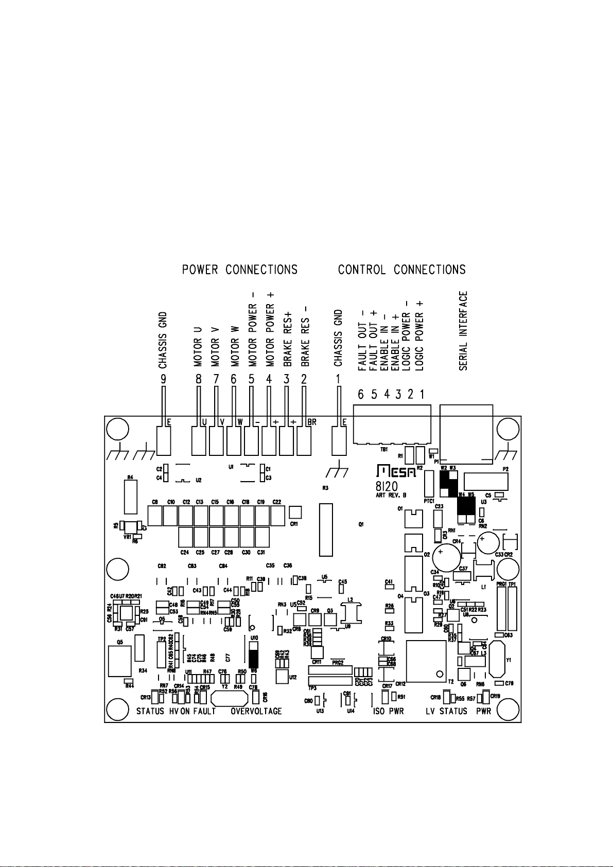
CONNECTORS
8I20 CONNECTOR LOCATIONS AND DEFAULT JUMPER POSITIONS

8I20 4
CONNECTORS
MOTOR - POWER - BRAKE CONNECTORS
The motor, motor power and brake connections are brought out on .250" spade
terminals on the top edge of the 8I20 card. From left t right the terminal functions are:
1 Chassis Gnd
2 Brake resistor -
3 Brake resistor +
4 Motor power +
5 Motor power -
6 Motor W
7 Motor V
8 Motor U
9 Chassis Gnd
LOGIC POWER/FAULT CONNECTOR
TB1 is the logic power/ fault output/enable input connector. TB1 is a sixterminal 3.5
mm pluggable screw terminal block. TB1 pinout is as follows:
1 Unregulated logic power +
2 Unregulated Logic power -
3 Enable in +
4 Enable in -
5 Fault out +
6 Fault out -

8I20 5
CONNECTORS
SERIAL PORT
J1 is the 8I20s serial interface. J1 is a RJ-45 jack. The serial interface pinout is
compatible with standard 8 wire CAT5 Ethernet cables. J1 pinout is as follows:
1 RXA
2 RXB
3 TXA
4 GND
5 GND
6 TXB
7 +5V
8 +5V
J1s pinout is designed to match breakout cards like the 7I44. A standard CAT5 or
CAT5E cable can be used to connect the 8I20 to a 7I44. CAT5E cable is suggested if the
serial cable is used for powering the 8I20, as the larger wire size result in lower voltage
drop.

8I20 6
OPERATION
LOGIC POWER
All logic on the 8I20 runs from 5V logic power. This can be supplied over the serial
cable, or via a oncard 5V regulator. Jumper W2 determines the logic power source. When
jumper W2 is in the ‘UP’ position, 5V logic power is suppled by the serial cable. Due to
voltage drop inthe serial cable. The8I20 shouldonlybe powered via the serial cablewhen
serial cable length is 8 feet or less. Typical 5V power consumption is 350 mA.
Logic power can also be supplied via the on card regulator and TB1. When W2 is
in the DOWN position, logic power comes from the on card regulator which is fed by TB1.
Unregulated power to TB1 pins 1 and 2 is regulated to 5V logic power. Unregulated input
to TB1 pins 1 and 2 can range from 8 to 40 VDC
MOTOR POWER
Motor power is supplied to the 8I20 via spade lugs #4 and #5. Motor power can
range from 35 to 400 VDC. All communication to the 8I20 will work down to 0V motor
power but the under-voltage fault setting will prevent motor operation at lower then ~35
VDC unless the default setting is changed. Default over-voltage fault is set for 385 VDC.
Voltages high that 385VDC will result in a overvoltage fault.
The8I20haslocalhighfrequencybypassingbutreliesonthepowersuppliesoutput
capacitors to supply dc power with less than ~15% ripple. The 8I20 also relies on power
supplyoutputcapacitorstostoremotorinductiveenergy.Forthisreason,powershouldnot
be disconnected from the 8I20 power input terminals when in operation. The 8I20 motor
power leads should use 18 GA wire and must be shorterthan 3 feet. That is, motor power
should not be routed more than 3 feet from the main power supply filter capacitors. Power
supply circuit breakers or fuses should be located on the power supply primary, not
between the 8I20 and power supply capacitors.
MOTOR BRAKE
To prevent regenerated motor power from creating a over-voltage condition, the
8I20 can dump regenerated motor power into a user supplied brake resistor. The brake
circuitry can provide a maximum of 15 amps of brakingcurrent. At the maximum BrakeOn
setting of 385 VDC, this equals a ~25 Ohm resistor for maximum braking current.
Actual brake on/off voltages are programmable. Default brake on voltage is 360
VDCanddefaultbrakeoffvoltageis340VDC.BrakeOnvoltagemustalwaysbesethigher
than BrakeOff voltage.
In addition to the programmable brake voltage settings, there is a fixed 385V
BrakeOn setting that cannot be changed. This is for 8I20 module protection.

8I20 7
OPERATION
MOTOR CONNECTIONS
The U/V/W motor connections are the direct PWM outputs of the 8I20s bridge.
Larger motors may have enough winding to frame capacitance to generate considerable
ground noise. This noise source can be reduced by:
1. Make sure that the motor frame ground signal is returned to the frame ground on the
8I20 card.
2. Use a ferrite bead as a common mode choke around all phase wires, that is the U/V/W
motor wires pass through a single bead. Do not route the frame ground wire through the
bead. A suggested ferrite bead is: Laird-Signal Integrity Products 28B1122-100.
ENABLE INPUT
The 8I20 has a isolated 4-24V enable input. This input must be driven to enable
motor drive. If enable input is not driven, the 8I20 will go into a fault state, and turn off
motor PWM.
FAULT OUTPUT
The fault output is an isolated transistor (OPTO coupler) output. The fault output is
off in non-masked fault conditions and on in normal operation. The fault output can supply
a maximum of 5 mA of output current and will switch voltages up to 24 VDC. Normally the
fault outputs of all 8I20s would be wired in series.
FAULT CONDITIONS
The 8I20 monitors many parameters and reports fault conditions in the FAULT
register. When a non-masked fault occurs, the 8I20 turns off motor drive and the current
control loop. The following is a list of the fault conditions:
NAME BIT FUNCTION
WATCHDOGFAULT 0 Communication timeout fault
NOENABLEFAULT 1 No external enable fault
OVERTEMPFAULT 2 8I20 PCB temperature > 85C
CURRENTFAULT 4 8I20 high side overcurrent Fault

8I20 8
OPERATION
FAULT CONDITIONS
NAME BIT FUNCTION
ULOOPCURRENTFAULT 5 U current >125% of MAXCURRENT
VLOOPCURRENTFAULT 6 V current >125% of MAXCURRENT
WLOOPCURRENTFAULT 7 W current >125% of MAXCURRENT
BUSLOVFAULT 8 Low motor voltage fault
BUSHIVFAULT 9 High motor voltage fault (settable)
MAXBUSVFAULT 10 High motor voltage fault (fixed at 400V)
MODULEFAULT 11 Module over temperature or low gate
voltage
OERRFAULT 14 8I20 serial port overrun error
FERRFAULT 15 8I20 serial port framing error
CLEARING FAULTS
Faults can not be cleared by writing the fault register but are cleared by setting the
CLEARFAULT flag. The host must then poll the state of CLEARFAULT until it is zero.
FAULT MASK
Certain faults can be masked so that they do not affect the external fault output.
CurrentlyonlytheBUSLOVFAULTismaskable.AzerobitintheFAULTMASKregisterwill
mask the corresponding fault bit.

8I20 9
OPERATION
STATUS REGISTER
The 8I20 maintains a status register that reflects various internal 8I20 conditions.
NAME BIT FUNCTION
ILIMITEDSTATUS 0 Indicates that MAXCURRENT is not
availabledueto8I20temperature/current
limiting.
BRAKESTATUS 1 Current brake on status
BRAKEWASONSTATUS 2 Brake has been applied status (sticky)
WDTO 4 DSP startup due to Hardware watchdog
timeout (sticky)
SWR 5 DSPstartupduetosoftwarereset(sticky)
EXTR 6 DSP startup due to external reset (sticky)
Sticky status bits remember events until low side power is removed or the status
register is cleared.

8I20 10
OPERATION
STATUS LEDS
The 8I20 has 7 on card status LEDs located on the bottom edge of the 8I20 card.
The status LEDs in left to right order:
LED COLOR NAME FUNCTION
CR13 Green DSP Status Blinks with host communication
CR14 Yellow HV On On when motor power is present
CR15 Red Fault On when drive fault is present
CR16 Red OverVoltage/Brake On when brake is applied
CR17 Green Isolated power Onwhenisolated poweris present
CR18 Yellow LV status On when isolated inverter is OK
CR19 Green LV power On when logic power is present
HEAT SINKING
The 8I20 requires additional heatsinking unless used for low continuous power
servo applications. When used to deliver its rated continuous 2.2KW power, the 8I20 can
dissipate up to 65W. Heatsink thermal resistance should be chosen to keep the module
temperature below 100C. For example, in a 50C ambient environment and continuous
2.2KW load, keeping the module temperature below 100C with 65W of power dissipation
requires a total thermal resistance of 100-50/65 = 0.77 C/W. The 8I20s mounting plate
adds to the thermal resistance.
Two styles of 8I20 mounting plates are available, right angle and parallel. The right
angleplatehas theadvantageof tighterpackingdensitybuthashigherthermalresistance.
The right angle mounting plate adds approximately 0.5C per watt to the 8I20s thermal
resistance. The parallel mounting plate adds onlyabout 0.1C per watt thermal resistance.
So for a parallel mount 8I20, the external heatsink thermal resistance needed to sustain
the full 2.2 KW continuous power is 0.77-0.1 = 0.67 C/W.
Achieving 0.67 C/W in a reasonable size normally will require fan cooling.

8I20 11
OPERATION
PC HOST ADAPTER
In order to run any of the command line utilities a RS-422 adapter is needed. Mesa
can provide a suitable adapter. Two such adapters are 3I21 or 3I22. These adapters
connects the RJ-45 RS-422 interface on the 8I20 to a DB9 serial port (3I21) or USB port
(3I22) and provide 5V link power.
MINIMAL HOST PC ADAPTER
A simple home made host adapter can be made by directly connecting RS-232
signals from a 9 pin PC serial port or USB RS-232 adapter to the 8I20s RS-422 signals
via a one ended CAT5 cable. A single resistor between RS-232 TXD and RS-422 RXB is
needed to prevent overloading the RS-232 TXD output
CAT5 PIN DE-9F PIN CAT5 SIGNAL DE-9F SIGNAL CAT5 COLOR
1 5 RXA GND ORANGE WHITE
2 3 RXB (1) TXD (1) ORANGE
3 XX TXA XX GREEN WHITE
4 5 GND GND BLUE
5 5 GND GND BLUE WHITE
6 2 TXB RXD GREEN
7 XX +5V (2) XX BROWN WHITE
8 XX +5V (2) XX BROWN
Notes:
1. Connect via 470 Ohm 1/4 watt resistor. All other signals directly connected
2. If not run from field power, +5V power must be supplied via the 8I20s serial cable

8I20 12
OPERATION
DRIVE PARAMETER SETUP
The 8I20 has both working and EEPROM drive parameters. The working
parameters are volatile (lost at power down) 8I20 uses the working parameters for all
normal operations. At powerup or reset, a subset of the workingparameters get initialized
from non-volatile EEPROM memory. Because of this, when adjusting parameters the
working parameters can be changed ‘live’ but changing the EEPROM parameters will not
have any effect until the 8I20 is reset. All EEPROM parameters have a NV prefix.
SETUP COMMUNICATION WITH 8I20
To enable communication between a PC and the 8I20 three things are required:
1. 8I20 must have logic power (normally supplied via TB1)
2. Setup jumper must be in "SETUP" position = DOWN
3. A RS-422 adapter must connect from the PCs serial port/ USB serial adapter to the
8I20.Thisadapterisavailablefrom Mesa(3I21,3I22)orhomemadeadaptershownabove
4. The parameter read and write programs are simple command line utilities that require
some environment variables to be set before use:
SET COMPORT = COM1 ( set to match the serial port )
SET BAUDRATE = 115200
SET PROTOCOL = LBP
WPD The WPD utility writes 8I20 parameters including non-volatile setup parameters. It
uses symbolic names for the parameters so numeric constants do not need to be
memorized, for example
WPD BRAKEONV 30000
Would set the working brake-on voltage parameter to 300V
(units of voltage are .1V)
WPD NVBRAKEONV 32000
Would set the EEPROM brake-on voltage parameter to 320V

8I20 13
OPERATION
DRIVE PARAMETER SETUP
WPD
WPD FAULT 0
Would clear the FAULT parameter
RPD The RPD utility reads a parameter from the 8I20. It uses symbolic names for the
parameters so numeric constants do not need to be memorized, for example:
RPD FAULT H
Would read the fault parameter as a Hexadecimal word
RPD BUSV
Would read the motor bus voltage (in units of 10 mv), that is a bus voltage of 320
would read as 32000
MAIN DRIVE SETUP PARAMETERS
For normal setup only a couple of parameters need to be changed to match a
specific motor. The most important are NVMAXCURRENT, NVBRAKEONV and
NVBRAKEOFFV.
MAXCURRENT
The MAXCURRENT parameter sets the full scale RMS motor current of the 8I20.
This is the single most important setup parameter needed to match the 8I20 to a specific
motor. This should be set to the maximum RMS motor current value (or to 30A if themotor
has a higher than 30 A RMS current rating). Current (torque) commands are signed 16 bit
numbers sent to the 8I20 and scaled such that:
RMS motor current = QISETPOINT * NVMAXCURRENT/3276700
MAXCURRENT is a unsigned 16 bit number with units of 10 mA, that is maximum
per phase current in Amperes is MAXCURRENT/100. Like most setup parameters,
MAXCURRENT is the working current limit, and NVMAXCURRENT is the non-volatile
EEPROM current limit.
For example:
WPD NVMAXCURRENT 2500
Would set the EEPROM maximum current parameter to 25A. This will not take
effect until the 8I20 is reset.

8I20 14
OPERATION
DRIVE PARAMETER SETUP
BRAKEONV and BRAKEOFFV
BRAKONV and BRAKEOFFV set the brake on and brake off voltage thresholds.
These are used to clamp the rising motor bus voltage created when decelerating. When
decelerating,the8I20willchargethemotorpowersupplyfiltercapacitorswithregenerated
energy .
The default values (on at 360V off at 340V) are chosen to match a 240V off line
power supply, and to protect the 8I20. If lower power supply voltages are used (with lower
filter capacitor voltage ratings) the BRAKEONV and BRAKEOFFVvoltages should be set
lower to protect the power supply. It is suggested that BRAKEOFFV be set 20V lower than
BRAKEON. BRAKEONV and BRAKEOFFV are specified in units of 10mV. That is a
BRAKEONV value of 30000 would specify 300.0 V.
The startup values of BRAKEONV and BRAKEOFFV are set with the parameters
NVBRAKEONV and NVBRAKEOFFV.
For example:
WPD NVBRAKEONV 19000
WPD NVBRAKEOFFV 17000
Would be suitable values for a 120V line operated supply with a maximum rating
of 200V. Note that like all EEPROM parameters, these settings will not take effect until the
8I20 has been reset.
OPERATE MODE BAUD RATE
The operate mode baud rate default is 2.5 MBaud. This should not be changed
unless needed for non-standard applications. Baud rates are selected by writing an index
value to the NVBAUDRATE parameter. The index numbers for available baud rates are
as follows:
INDEX BAUD INDEX BAUD INDEX BAUD
0 9600B 1 19200B 2 38400B
3 57600B 4 115200B 5 230400B
6 460800B 7 921600B 8 1.25MB
9 2.5MB* 10 5MB 11 10MB

8I20 15
OPERATION
CURRENT LOOP TUNING
The 8I20 has settable tuning parameters for its PI current control loop. The
parameters are KQP, KDP, KQI, and KDI. KQP and KDP are the Proportional terms and
KQI and KDI are the Integral terms. Normally KQP should equal KDP and KQI should
equal KDI. The Startup values of KQP, KDP, KQI, and KDI are set by the cooresponding
EEPROM parameters NVKQP, NVKDP, NVKQI, and NVKDI. Default values forNV KQP
and NVKDP are 50 and default values for NVKQI and NVKDI are 150000. These defaults
are suitable for a large range of motors, but may need to be changed to optimize current
loop operation for specific motors.

8I20 16
CONTROLLERS
MULTI-AXIS CONTROLLERS
Two basic types of multi-axis controllers are available for use with the 8I20, host
based and "Smart". Host based controllers use the host computer to read encoders and
output angle and run a PID loop that outputs torque commands to the 8I20. The HostMot2
FPGA firmware suite is a host based motion controller that is compatible with the 8I20.
Smart controllers like SoftDMC take higher level motion commands from the host and
control all low level processes like reading encoders, running the PID loop and flagging
error conditions.
HOSTMOT2 8I20 INTERFACE
The Hostmot2 interface to the 8I20 is a smart serial interface for Mesa’s Anything
I/O series of FPGA cards that encapsulates the serial protocol details and presents a
simpleparallelregistersettothehost computer.Registersforwritingtorqueandangleand
registersforreadingbusvoltage,cardstatus,communicationstatus,andcardtemperature
are provided for all connected 8I20 cards.
The 8I20 Hostmot2 interface is a sserial module with specific firmware (SSLBP) for
8I20 card or other LBP interfaced cards. Each sserial module can support up to eight 8I20
cards. The sserial module supports the standard 2.5 M Baud communication rate and
torque update rates to 5KHz. With the default configuration, the Hostmot2 interfacesends
referenceangle(ANGLEparameter)andcurrent(QSETPOINTparameter)commandsand
receives bus voltage (BUSV parameter), 8I20 card temperature (TEMPERATURE
parameter), and 8I20 status and fault information (STATUS and FAULT parametera).
A complete host based controller will also need position sensing. This may consist
of quadrature encoders, SSI absolute encoders (including magnetic absolute types), or
resolvers. All three types of position sensors are available in the Hostmot2 firmware suite.
SOFTDMC 8I20 INTERFACE
SoftDMCisasmartmulti-axismotioncontrollerwithbuiltinmotionprofilegenerator,
programmable exception handling and a high performance FIFO based host interface.
SoftDMC is a firmware option for Mesa’s Anything I/O series of FPGA cards. For more
information on SoftDMC, please consult the SoftDMC manual.
ANYTHING I/O INTERFACE DAUGHTER CARDS
8I20 compatible daughter cards are available to simplify connecting the 8I20 to
Mesa’s Anything I/O FPGA cards. One interface card is the 7I44. The 7I44 provides 8
channels of RS-422/RS-485 serial communication interface. The 7I44 uses RJ-45
connectors for the serial interface. These connectors are compatible with the 8I20 so a
common CAT5 or CAT5E cable may be used to connect from the 7I44 to the 8I20. The
7I44 can also provide 5V power to the 8I20 subject to the CAT5/5E cable length
restrictions.
Table of contents
Popular DC Drive manuals by other brands


SEMIKRON
SEMIKRON SEMITOP E2 Technical Explanation

DANA
DANA Spicer Torque-Hub W3B Series Service manual

ABB
ABB ACS580-07 Hardware manual

Parker
Parker 650 Series Safety Booklet & Quickstart

Ametek
Ametek dunkermotoren BG 95x40 dPro CO Translation of the original function and connection guide

Danfoss
Danfoss VLT Midi Drive FC 280 Programming guide

ABB
ABB ACS580 Series Hardware manual

Columbus McKinnon
Columbus McKinnon PFFAF-silberblau ALS 10 Operating instruction

Inovance
Inovance MD380 Series user guide

Vicon
Vicon 239-03-00 Series Installation & configuration guide

Danfoss
Danfoss VLT FC 300 instruction manual

Schellenberg
Schellenberg MarkiDrive PREMIUM manual