Mesalabs Defender 530 User manual

Defender™530
User Manual

Table of Contents
Introduction ............................ 1.0
Operation ................................... 2.0
Battery ........................................2.1
Activation ....................................2.2
Connections .................................2.3
Display Screen .............................2.4
Menu Navigation ..........................2.5
Set Up .........................................2.6
Measurements .............................2.7
Single ..........................................2.8
Burst ...........................................2.9
Continuous ..................................2.10
Data Port .................................... 3.0
DryCal Pro Software .....................3.1
Defender Firmware Upgrades ........ 3.2
Annual Maintenance & Cal ......... 4.0
Shipping ..................................... 5.0
Storage ....................................... 6.0
Defender 530 Specications ...... 7.0
Factory Default Settings ............ 8.0
Limited Warranty ....................... 9.0
Troubleshooting ......................... 10.0

Introduction
Operation
Data Port
Annual Maintenance and Calibration
Shipping
Storage
Defender 530 Specications
Factory Default Settings
Limited Warranty
Troubleshooting
2.0
6.0
3.0
7.0
4.0
8.0
5.0
9.0
10.0
1.0

2
The Defender 530 measures both volumetric and standardized gas ow with a volumetric
ow accuracy of 1% and standardized ow accuracy of 1.2% of reading. It uses our Prov-
en DryCal Technology to measure volumetric gas ow and is manufactured in our accred-
ited laboratory in Butler, NJ.
This manual will provide information needed to operate your Defender. If at any time you
have questions regarding its operation, please contact Mesa Labs through our Web site
(drycal.mesalabs.com) or call 973.492.8400 to speak with a member of our professional
customer service staff.
Your Defender
Your Defender comes with the following:
• AC Power Adapter/Charger
• PC Serial Cable
• Leak Test Caps (2); Save for use during the Leak Test
• Calibration Certicate
• Manual
Carrying cases and accessories are available for purchase from Mesa Labs or your distrib-
utor.
1.0 Introduction
2

3
Data Port
Suction Fitting
Measuring Cell
Pressure Fitting
Charging Jack
Calibration Label
Reset Button
Display
Anti-tamper Label
1.0
3

4
2.1 Battery
Charging, installing and monitoring your Defender battery
Your Defender battery is charged at the factory, but we recommend that you make sure it
is fully charged before initial use.
• Connect the AC power adapter to the Defender’s Charging Jack (DC In).
• Plug the AC power adapter into an AC outlet.
Initial charging should take about eight (8) hours.
After the initial charge:
• You may continue to charge your Defender indenitely simply by leaving it connected to
the AC power adapter.
• Be sure to charge the battery at least every three (3) months, to maintain battery life.
The battery symbol on the LCD display indicates your Defender’s battery charge condition.
A shaded battery icon indicates a full charge. As the battery voltage drops, the indicator
will empty in 20% increments.
2.0 Operation
4

5
2.0
Disposal:
In compliance with the European Union CE directive 2006/66/EC the battery in your De-
fender should be removed for recycling prior to disposal of the Defender. The battery in
the Defender is a valve regulated sealed lead acid battery. Please note that opening the
Defender may damage connections so this procedure should only be used for battery dis-
posal.
Procedure:
Remove ve Phillips head screws on the back of the Defender; one will be located under
the calibration void label. Lift off the rear cover and disconnect the two pin connector from
the battery to the printed circuit board. Lift the battery from the case.
5

6
2.2 Activation
Turning your Defender on and off
Simply press the power button.
• Press the On/Off button for 1 second to turn on your Defender.
• When rst turned on, your Defender displays an opening screen showing the product
name, model number and ow range.
• Press the On/Off button for 3 seconds to turn your Defender off.
2.3 Connections
Attaching your Defender to a device
Connect device to be calibrated to the appropriate Defender port. Use 1/4 inch diameter
tubing.
• Connect to outlet at top (suction tting) when a device draws air (such as sampler).
• Connection tubing to bottom inlet for devices that push air in (pressure devices).
6

7
2.4 Display Screen
Understanding the screen components
The Defender 530 provides a menu of operational settings and commands. The four di-
rectional arrow buttons on the control panel allow you to navigate through the menu and
select the desired settings for your Defender. Your location within the menu is highlighted
for easy identication.
2.5 Menu Navigation
Moving through operational menus
• Use the directional arrows , , and on the control panel to nd your way
through the menu.
• When your desired command is highlighted, simply press the ENTER button on the
control panel.
If you see a menu selection within angle brackets (<….>), that means you have multi-
ple options for an item. Press the left or right (or ) arrow button to see the options.
If you wish to use the factory settings proceed to section 2.7 Measurements.
2.0
7

8
LCD Screen
Control Panel
On/Off Button
8
Highlight CONFIRM after making changes and press the Enter button to save the
changes made.
‘Conrmed, New Settings Will be Retained’ message will appear in the screen for a
brief period before it returns to Setup menu.
Highlighting EXIT and then pressing the Enter button will return you to the SETUP
menu without saving any submenu changes.
Defender 530 M
Range: 50–5,000 mL/min
with DryCal Technology®
MEASURE | SETUP
2.6 Set-up
Customizing the Defender to your needs
You can customize your Defender in the SETUP menu. Highlight SETUP in the introduc-
tion screen to enter the Setup Menu. Or, highlight SETUP after resetting and then exiting
a measurement mode screen. The SETUP menu has eight submenus.
• Readings • Date • Diagnostics
• Units • Preferences • About
• Time • Power
To select a submenu, use the directional arrow buttons to highlight the submenu and
press the Enter button.
In submenus, brackets (i.e., <...>) indicate different selection options. You can switch
back and forth by pressing the forward or backward (or ) arrow.

9
2.0
9
Readings
Choose the ow reading type to either volumetric ‘Vol’ or standardized ‘Std’. Volumetric
ow is the actual ow at the ambient temperature and pressure whereas the standard-
ized ow indicates a ow rate at a specic temperature and pressure. Standardizing pres-
sure is set to a default value of 760 mmHg whereas standardizing temperature is an user
settable value set at ‘Std To’ in the ‘Units’ sub-menu.
Choose the number of measurements in the average from 1 to 100.
If you wish to incorporate a time delay between consecutive measurements, set Time
Between from 1 to 60 minutes.
Set the Sensor Factor to any value between 0.200 to 3.000. Sensor factor scales the read-
ing for calibrating MFCs and MFMs with surrogate gases. Sensor factor affects the ow
rate measurement only when the reading ‘Type’ is set to standardized ‘Std’.

10
Units
Measure gas Flow in cubic centimeters, milliliters, liters or cubic feet (all units are
per minute).
Measure Pressure in mmHg, kPa or PSI and Temperature in Celsius or Fahrenheit.
Set the standardizing temperature by setting ‘Std To’ to a value from 0 to 50 deg C or 32
to122 deg F. ‘Std To’ effects the ow rate measurement only when the reading ‘Type’ in
the ‘Reading’ sub-menu is set to standardized ‘Std’.
Time
Set the current time and the format.
The format can be selected as PM, AM, or 24H.
Date
Set the date and the format.
The format can be selected as DD (day)-MM (month)-YYYY (year) or MM (month)-
DD (day)-YYYY (year).
10

11
2.0
11
Preferences
Read Default
Select a preferred mode of measurement when the Defender is initially turned on.
Default Settings
Select <No> to allow the ‘Read Default’ change. Selecting <Yes> will reset your Defender
to the factory default settings. (Factory default settings are provided elsewhere in this
manual.)
Data Port
Set the data port interface by selecting:
<BIOS> to operate with Bios DryCal software.
<SKC> to operate with SKC CalCheck®Interface.
Magnication
Controls the amount of data on the display. Select <Zoom> to view only ow measure-
ments in larger font, or select <Detail> to simultaneously view ow measurements,
temperature, and pressure in a smaller font.
Power
Power Save
By selecting <On>, your Defender will save power by turning off after ve minutes of
inactivity. However, it will not turn off when connected to the AC power adapter/charger.
Select <Off>, and your Defender will remain on until you manually turn it off.
Backlight
Select <On> to illuminate the LCD display or <Off > to conserve battery power.
12
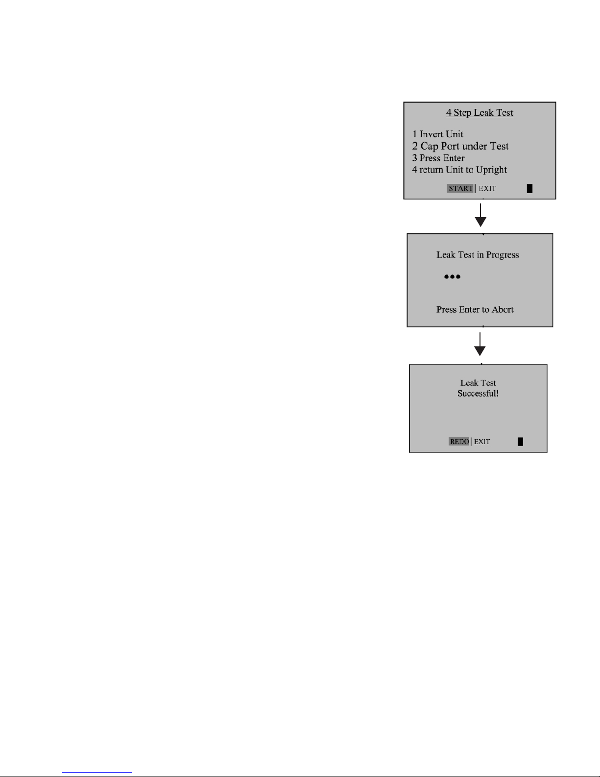
Diagnostics
The Defender leak test is designed only to verify the
internal integrity of the instrument and alert you to an
internal leak. We recommend performing the Leak Test
only as an intermediate quality control check or when-
ever the integrity of the instrument is questioned due
to misuse or accidental damage.
Please note that a leak test is not a substitute for a
comprehensive examination of the unit’s overall per-
formance and it does not ensure that your Defender is
operating accurately.
• Invert your Defender and allow the piston to travel to
the top.
• Cap the port under test using the supplied leak test
cap. Leave the other port uncapped.
• Press Enter on the control panel while the unit is still
inverted.
• Return the unit upright. The leak test will progress.
12

13
2.0
13
Out of Range
If the ow you are measuring is outside the Defender’s ow range, (see section 7 De-
fender Specications for ranges), the “Out of Range!” warning appears. Immediately
lower or disconnect the ow. When the ow is within the proper range, select RESET to
clear your Defender’s last measurement.
About
This screen provides basic information about your Defender, which may be an especially
helpful reference when speaking to a technical support representative or your distributor.

14
14
2.7 Measurements
Taking gas ow readings
To maintain the best possible accuracy and minimize thermal effects, Mesa recommends
fully charging your battery before taking measurements. If this is not possible, we recom-
mend disconnecting your Defender from its AC power adapter/charger while taking ow
measurements — or to run gas through your Defender for 10 minutes before starting the
ow measurement.
First steps
Press the power button.
• Press the On/Off button for 1 second to turn on your Defender.
• When rst turned on, your Defender displays an opening screen showing the product
name, model number and ow range.
• Press the On/Off button for 3 seconds to turn your Defender off.
Connect device to be calibrated to the appropriate Defender port. Use ¼ inch diameter
tubing.
• Connect to outlet at top (suction tting) when a device draws air (such as sampler).
• Connect to inlet at bottom (pressure tting) when a device pushes air.
• Do not cap the unused port on the Defender.
• Select the reading type to Vol or Std. Set ‘Std To’ to the desired standardizing tem-
perature
• Choose the measurement type, Single, Burst, or Continuous, then press enter.

15
2.8 Single Measurement
Each time the ‘Enter’ button is pressed, one measurement will be made. When each
subsequent measurement is made, the current ow and average of all prior readings will
be displayed.
2.0
15
2.9 Burst Measurement
This setting functions in the same manner as ‘SINGLE’, but measurements continue
automatically until the preset number of measurements has been made. Operation then
ceases, and the last reading and average are displayed.
Press ‘Enter’ again to begin another preset sequence.
2.10 Continuous Measurement
This setting functions in the same manner as ‘BURST’, but new sequences will automati-
cally repeat until stopped by the user.

16
16
Note:
(010 in series) indicates the number of measurements. 10 is the factory-preset number.
Dene the number of measurement you prefer, from 1 to 100, by accessing the SETUP
menu.
In Continuous or Burst mode, select:
• PAUSE to terminate the current ow measurement but to leave the average ow mea-
surement and previous ow measurement on the screen. This allows you to resume
the ow measurement sequence if you wish to do so.
• RESET to terminate the ow measurement and clear the screen.

17
3.0 Data Port
3.0
2.0
3.1 DryCal Pro Software
Visit Mesa’s website to download your copy of DryCal Pro software (http://
www.mesalabs.com/drycal-pro/) . DryCal Pro captures ow data from your
Defender directly to a pre-congured table. The data can be exported to se-
lectable Microsoft ofce environment.
To run DryCal Pro, you must have Windows®XP or 7, Microsoft Excel®2003
and up, and a RS232 port, or if your PC does not have an RS-232 port you
will need a USB to RS-232 adapter.
3.2 Defender Firmware Upgrades
The Defender rmware is upgradable through the Data Port. Contact techni-
17

18
18
4.0
4.0 Annual Maintenance and Calibration
Assuring top performance and accuracy
Your Defender is a precision measuring standard with moving parts
machined to extremely close tolerances. Various environmental factors,
product wear, drift of sensors, or inadvertent damage may adversely affect
your Defender’s measurement accuracy or general performance. For these
reasons, Mesa Labs highly recommends having your Defender annually
veried by an ISO 17025–accredited laboratory, such as our Butler, NJ facil-
ity, to ensure its measurement integrity.
For the ultimate in Defender maintenance and to take advantage of any
available software and mechanical upgrades, Mesa Labs offers an annual
non-mandatory Recertication program. This is a service package that
provides complete product refurbishment, testing and available upgrades;
calibration and NIST-traceable calibration certicates.
Recertication includes a 90-day service warranty should any related labor
or parts replacements prove faulty.
Turnaround time is generally two weeks from time of receipt. Expedited
48-hour turnaround is available.
3.0
Table of contents
Other Mesalabs Measuring Instrument manuals


